
User Manual
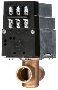
Emerson 1300 Series Hydronic Zone Valves
1300 Series valves for zoning systems up to 50 PSI operate quietly and efficientlyproviding years of reliable service.
FEATURES
- Self-aligning barrel-type valve stem design
- Made of a corrosion-resistant stainless steel
- Motor can be removed from valve assembly without draining system
- Built-in auxiliary contacts to control burner or circulator relay
- Automatic recycling manual operator shows valve position at all times
- Screw terminal wiring panel for added convenience
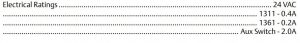
SPECIFICATIONS
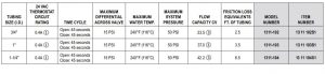
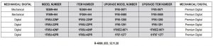
3-WIRE, 24V VALVES WITH SCREW TERMINAL WIRING PANEL AND AUXILIARY SWITCH (See table at bottom for compatible thermostats)
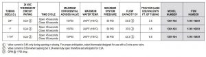
2-WIRE, 24V VALVES WITH SCREW TERMINAL WIRING PANEL AND AUXILIARY SWITCH
1311 COMPATIBLE THERMOSTATS TABLE
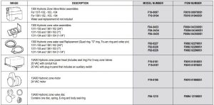
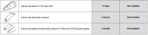
PARTS AND ACCESSORIES
1311 THREE-WIRE ZONE VALVE

TERMINALS 1, 2 = POWER TO VALVE1 = 24 VAC NEUTRAL2 = 24 VAC HOT
TERMINALS 5,4,6 = SPDT THERMOSTAT5 = POWER (SAME AS 2 INTERNALLY)4 = OPENS VALVE6 = CLOSES VALVE
TERMINALS 2, 3 = AUXILIARY SWITCH2, 3 BECOME SAME POINT ON CALL FOR HEATTERMINALS 1, 3 = POWER OUT TO AUXILIARY CIRCUIT ON CALL FOR HEAT
TROUBLESHOOTING:
- Attach a voltmeter to terminals 1 and 2. Power (24 volts) should always be present on 1 and If power is interrupted check transformer or power source.
- With a voltmeter attached as above, jumper terminals 5 and 4 to verify the valve opens. If power is present on 1 and 2 but the valve fails to open check connections. Replace motor assembly (replacement Motor # F19-0097) if condition persists. When the valve opens, break the connection between 5 and 4 and jumper between 5 and 6. The valve should close. If the valve fails to close replace motor assembly.
- Terminals 2 and 3 (auxiliary circuit) become the same point electrically when the valve opens. Because terminal 2 is 24 volts hot, a voltmeter should read 24 volts between terminal 3 and terminal 1 (neutral) when the valve is open.
NOTE: If the auxiliary circuit terminals (2 and 3) are being attached to a control circuit with a separate transformer the transformers must be in phase or one transformer may be damaged. If phasing the transformers is not possible a 24 volt isolation relay can be installed with the coil attached to terminals 1 and 3 and the contacts can be used to operate the control circuit. The relay will energize when the valve opens.
For complete installation instructions visit our website.
1361 TWO-WIRE ZONE VALVE
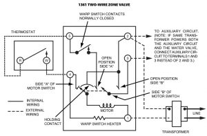
TERMINALS 1, 2 = POWER TO VALVE1 = 24 VAC NEUTRAL2 = 24 VAC HOT
TERMINALS 2, 4 = SPST THERMOSTATMAKE TO OPEN, BREAK TO CLOSE
TERMINALS 2, 3 = AUXILIARY SWITCH2, 3 BECOME SAME POINT ON CALL FOR HEAT
TERMINALS 1, 3 = POWER OUT TO AUXILIARY CIRCUITON CALL FOR HEAT
TROUBLESHOOTING:
- Attach a voltmeter to terminals 1 and 2. Power (24 volts) should always be present on 1 and If power is interrupted check transformer or power source.
- With voltmeter attached as above, jumper terminals 2 and 4 to verify the valve opens. If power is present on 1 and 2 but the valve fails to open check connections. Replace motor assembly (Replacement Motor # F19-0104) if condition persists. When the jumper is removed between 2 and 4 the valve should close. If the valve fails to close replace motor assembly.
- Terminals 2 and 3 (auxiliary circuit) become the same point electrically when the valve opens. Because terminal 2 is 24 volts hot, a voltmeter should read 24 volts between terminal 3 and terminal 1 (neutral) when the valve is open.
NOTE: If the auxiliary circuit terminals (2 and 3) are being attached to a control circuit with a separate transformer the transformers must be in phase or one transformer may be damaged. If phasing the transformers is not possible a 24 volt isolation relay can be installed with the coil attached to terminals 1 and 3 and the contacts can be used to operate the control circuit. The relay will energize when the valve opens.
For complete installation instructions visit our website.
Emerson 1300 Series Hydronic Zone Valves User Manual – Emerson 1300 Series Hydronic Zone Valves User Manual –
Questions about your Manual? Post in the comments!
[xyz-ips snippet=”download-snippet”]