User Manual
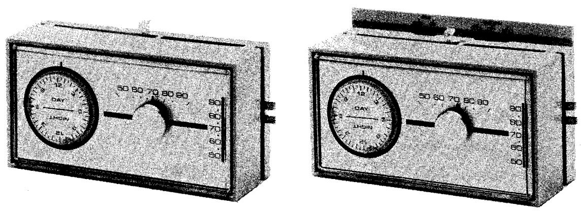
Emerson 1F70 Series Autometic Set Back / Set Up Thermostats
YOUR NEW THERMOSTAT
NO TE: THIS HOMEOWNERS GUIDE IS A UNIVERSAL MANUAL WHICH COVERS ALL VARIATIONS OF THE EN TIRE LINE OF MECHANICAL CLOCK THERMOSTATS. YOUR THERMOSTAT MAY NOT HAVE EVERY OPTION OR MAY VARY SLIGHTLY.

1F72HEATING ONLYCOOLING ONLY
…Can save between 10 to 16% on annual heating fuel bills depending on the climate of the city you’re living in.
It’s fast and easy to install, needs no additional wiring and can pay for itself in less than one year in most locations … just with the oil, gas, or electricity (depending on the fuel you use) that it saves.
Setting temperatures lower also provides additional comfort. Most families enjoy sleeping in cooler temperatures in both summer and winter. Your thermostat gives you this automatically.
THERMOSTAT FAMILIARIZATION (SEE FIG. 1)
Terms you must know to use your new thermostatNOTE: Thermostat shown with cover removed.
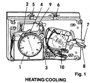
- Timer Dial (Rotates in counterclockwise direction)
- Blue Time Selectors For LOW Temperatures
- Red Time Selectors For HIGH Temperatures
- Time Reference Mark (Actual Time)
- Fan Selector (Auto-On)
- System Sel ector Switch (Cool-Off-He at)
- Red Temperature Setting – HI Lever
- Blue Temperature Setting Lever – LO Lever
- Battery (various sizes)
- Anticipator (not adjust able on all models)* Heating/Cooling Model Only
PROGRAM ADVANCE SWITCH (SEE FIG. 2)
The Program Advance Switch (featured on some models) allows the user to TEMPORARILY change the thermostat operating mode (set-up or set-back) without affecting automatic operation or timer programming. When using the daytime set-back and a family member arrives home early, the Program Advance Switch can be used to initiate an EARLY set-up without making any other thermostat adjustments. If the home will be unoccupied earlier than normal, the Program Advance Switch can be used to start the set-back period before its normally scheduled time.
By being in either the RED (left) position, or BLUE (right) position, the Program Advance Switch reflects the current operating mode of the thermostat:
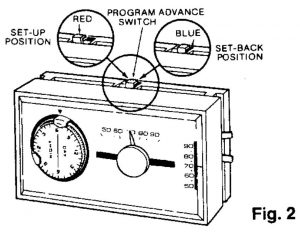
PROGRAM ADVANCE SWITCH
RED (LEFT) POSITION = SET-UP MODEBLUE (RIGHT) POSITION = SET-BACK
MODE
CAUTION: The Program Advance Switch SHOULD NOT be used within one hour BEFORE OR AFTER A RESET POINT.
SETTING TIMER
(SEE FIGS. 3, 4 & 5)
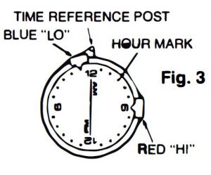
NOTE: Make sure you have set the time indicators to the proper am/pm or day/night positions on the dial.
The timer has been preset at the factory for normal heating season operation. Other settings may be selected as follows:
STEP 1. Remove thermostat cover.STEP 2. Decide what set-up and set-back times are desired. Refer to chart on page 7 for examplesSTEP 3. To change the positions of the time indicators, rotate dial counterclockwise until BLUE indicator is at bottom of timer.
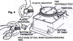
NOTE: An additional set of time indicators is stored in the thermostat cover on some models. For double set-back, (two periods of lowered temperature) attach the additional indicators on dial as described below.STEP 4. Lift front portion of BLUE snap-on indicator away from dial face and over ridge around dial. After front portion clears ridge, pull indicator down and toward timing mechanism. See figure 4.STEP 5. Rotate timer dial until RED indicator is at bottom of timer. STEP 6. Remove RED indicator (follow STEP 4).STEP 7. Rotate timer dial until desired SET-BACK time is at bottom of timer.STEP 8. Push BLUE snap-on indicator onto EDGE of timer dial until it snaps into position.STEP 9. Rotate timer dial until desired SET-UP time is at bottom of timer.STEP 10. Push RED indicator onto edge of timer dial until it snaps into position.STEP 11. Rotate timer dial one complete revolution COUNTERCLOCKWISE (![]() ) PAST correct time of day.STEP 12. Continue counterclockwise rotation (
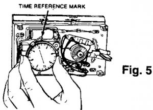
) PAST correct time of day.STEP 12. Continue counterclockwise rotation (![]() ) until correct time is ONE HOUR beyond time reference post. (If counterclockwise rotation was continued more than two hours past reference post, repeat 11 thru 13.)STEP 13. Rotate dial CLOCKWISE(
) until correct time is ONE HOUR beyond time reference post. (If counterclockwise rotation was continued more than two hours past reference post, repeat 11 thru 13.)STEP 13. Rotate dial CLOCKWISE(![]() ) to correct time.STEP 14. Snap on thermostat cover.
) to correct time.STEP 14. Snap on thermostat cover.
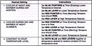
EXAMPLES
TIMER SETTING EXAMPLES (WINTER OR SUMMER)
SETTING TEMPERATURE (SEE FIG. 6)
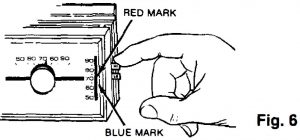
Setting Thermostat to Desired Temperature LevelMove the HI Temperature Setting lever to the highest temperature desired. Move the LO Temperature Setting lever to the lowest temperature desired. T he difference between the two temperature settings is the amount set-back or set-up which will result.
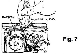
BATTERY REPLACEMENT (SEE FIG. 7)
Replacing Standard “AA’ Alkaline BatteriesThe battery that powers the Timer is a standard “AA’ type alkaline battery.
If Timer has stopped or does not keep accurate time, replace the battery.
It is recommended the battery be replaced routinely, once a year to maintain uninterruptedservice. ONLY USE ALKALINE TYPE “AA’ BATTERIES.
Pry battery out by inserting a small screwdriver in slot and pry outward. When installing new battery, make sure the positive ( +) end of the battery is toward the right.
Replacing Rechargeable Batteries (Nicad)The battery that powers the Timer is kept fully charged automatically by the 24-volt thermostat electrical circuit. Normal battery life expectancy is approximately six years. If, after this period the timer slows or stops, remove thermostat cover and replace battery.
Pry battery out by inserting a small screwdriver in slot and pry outward. When installing new battery, make sure the positive ( +) end of the battery is toward the right. Incorrect installation will damage battery.
If the timer does not run, or stops after installation, move both temperature levers to their lowest
setting. (The automatic recharging circuit is then connected to the battery.) Leave the temperature levers at their lowest setting for two or three hours. This will provide sufficient charge for the battery to operate the timer. The battery is automatically charged whenever the thermostat is not calling for heat (or cooling – if so wired).
After replacing battery, let heating or cooling system cycle at least 3 hours (to charge battery) then check time reference mark for correct time of day.
NOTE: If battery is installed on a day when extreme outdoor temperatures are experienced and heating or cooling system is on for long periods of time, as much as 24 or 48 hours may be required to charge the battery.
On heating/cooling models , to shorten the time required to obtain the initial battery charge, the system selector switch on the sub base may be moved to the “Off” position. The battery will thus obtain its initial charge in approximately 3 hours.
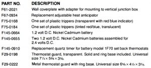
PARTS AND ACCESSORIES
SPECIFICATIONS
ELECTRICAL RATING : Heating: 24 volts 60 Hz. 0.15 to 1.0 ampCooling: 1.5 amps max. @ 30V 60 Hz. max.
HEAT ANTICIPATOR: Adjustable from 0.15 to 1.0 amp.
COOL ANTICIPATOR: Fixed for 30VAC max.
TEMPERATURE SELECTORS:High temperature – Red;Low temperature – Blue
TIMER FUNCTION:
- Raises or lowers room temperature to levels selected by Hi-Lo Temperature Levers for one or more periods of time every 24 hours. MINIMUM RESET PERIOD IS 2 HOURS. (4 HOURS ON SOME MODELS)
- Dial turns counterclockwise, and reads AM/PM or DAY/NIGHT.
- Adjustable indicators to select reset times.RED for Set-up (Hi Temp)BLUE for Set-back (Lo Temp)
- Powered by either a standard “AA’ alkaline battery, a rechargeable NI-CAD battery or 24.0 volts AC from heating/cooling system.
PROGRAM ADVANCE SWITCH:(Featured on some models)
- Allows temporary change of operating mode (Set-Up or Set-Back) without affecting/ changing timer settings. Not for use within one hour before or after a timer reset point.
MOUNTING:Heating Only – Cooling Only – Wiring wallplate mounts with two screws.Heat – Cool Combination – Using 825 wiring subbase mounts with two screws. Has System and Fan selector switches.
To call our technical service department (8:00 A.M. to 4:30 P.M. C.S.T.) dial 1-314-577-1300 or toll free 1-800-876-TECH.
Printed in U.S.A. Part No. 37-40898 8841
Emerson 1F70 Series Autometic Set Back / Set Up Thermostats User Manual – Emerson 1F70 Series Autometic Set Back / Set Up Thermostats User Manual –
Questions about your Manual? Post in the comments!
[xyz-ips snippet=”download-snippet”]