EMERSON 810-1600 Programmable Touchscreen Thermostat
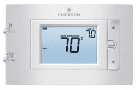
The Emerson Programmable Touchscreen Thermostat (P/N 810-1600) is a configurable device intended for light commercial applications. The thermostat is a communicating, intelligent sensor and controller combination with built-in temperature and humidity sensors used to control systems such as conventional Rooftop Units (RTU) and Heat Pumps(HP). The thermostat communicates over a Modbus RTU network that easily integrates with a building management system (BMS). For more information, download the full user manual (P/N 026-1739) here:https://climate.emerson.com/documents/026-1739-emerson-programmable-touchscreen-thermostat-installation-operation-manual-en-5390496.pdf
Thermostat Installation and Mounting

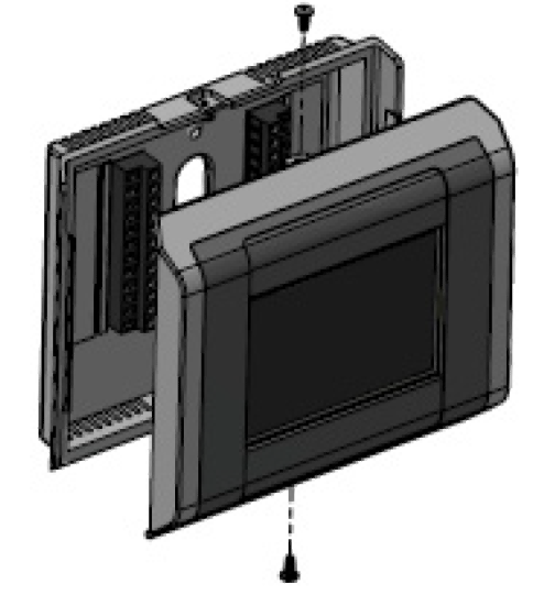 To open the thermostat enclosure, grip the top and the bottom edge of the front part of the device and pull straight. A certain physical resistance is normal from the 24x contacts pins (terminal strips and terminal blocks) that have to be separated during the operation.To close the thermostat enclosure, make sure to align the top and the bottom tabs between the front part and the baseplate, and then push the front part firmly toward the wall. Again, some force is required to mate both parts.Note that both top and bottom securing screws are optional and normally not installed on the units.To fix the baseplate on a wall, pass the wires through the opening of the baseplate, and use either 2x self-taping screws and dry-wall anchors, or regular 6-32 machine screws to attach on a standard single-gang electrical junction box (2” x 4”).
CAUTION! Do not over-tighten the screws when attaching the baseplate on a wall as physical damage may occur.Keep the thermostat housing and vents clean and free of any debris to avoid malfunction of the device.
The thermostat should be mounted:
- About 5 ft (1.5 m) from the floor.
- On a part of wall without hidden pipes or ductwork.
- In a room that operating limits are within 32°F to 122°F (0°C to 50°C).
- In a room that humidity operating range is within 0% to 95% relative humidity, non-condensing.
The thermostat should not be mounted:
- Nearby a window, on an outside wall, or next to a door leading to the outside.
- Where exposed to direct light and heat from any heat source, such as a lamp, the sun, a fireplace, or any heating element which may cause a false reading (temperature measurement offset).
- Nearby a direct airflow from supply registers (air vent or duct outlet).
- In areas and locations with poor air circulation such as behind a door.
Thermostat Wiring and Connections
Once the baseplate is affixed on the wall, proceed with the wiring connections to the terminal block.
Thermostat Power and Communication Matrix
| Thermostat Power | Thermostat Communication | ||
| R | 24VAC Power Supply | B+ | RS-485 + Signal |
| Rc | 24VAC Power Supply for Y1, Y2 | A- | RS-485 – Signal |
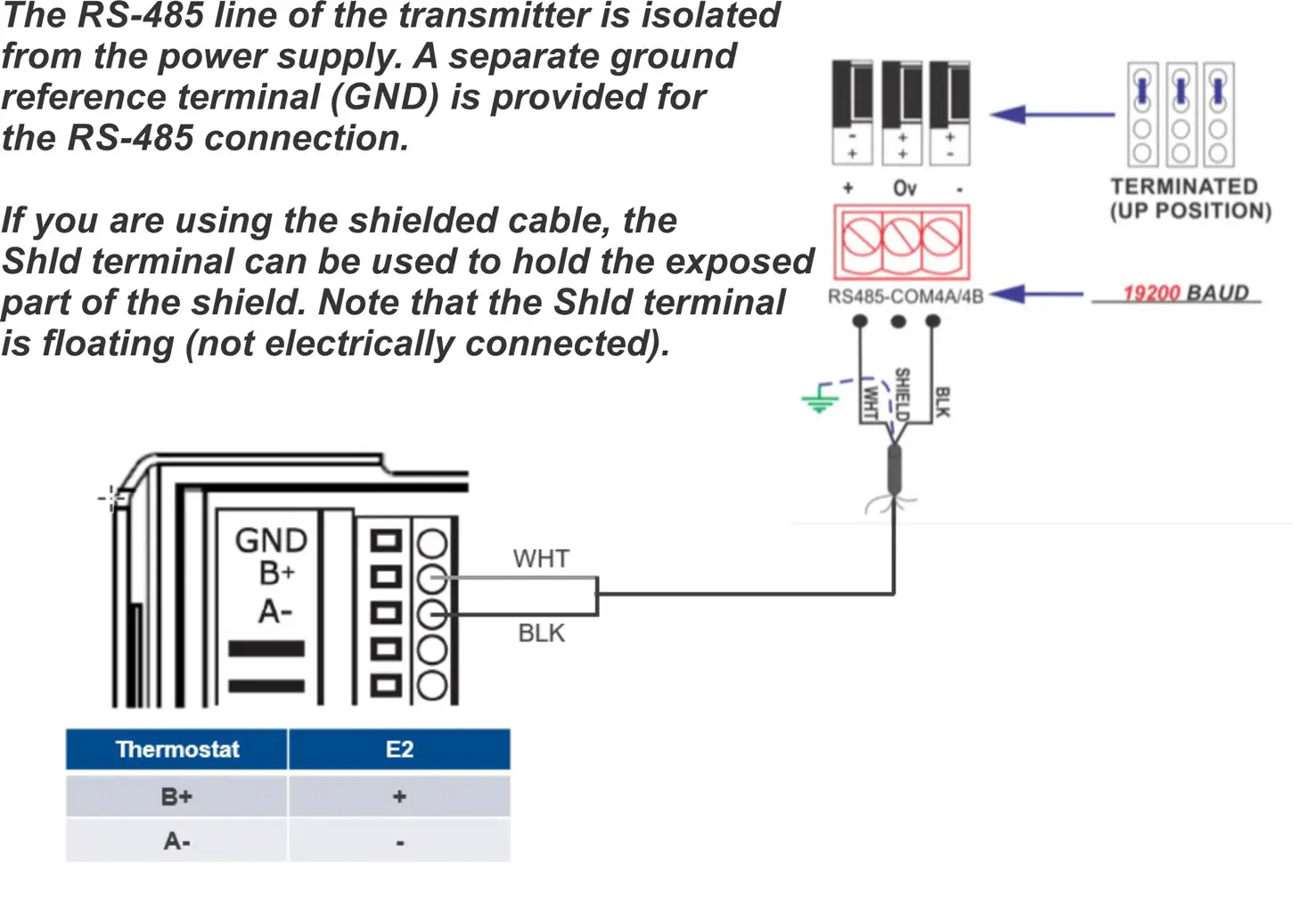
| C | 24VAC Power Supply Common | GND | Ground Reference for DC signals |
Wiring and Connections
| 2H / 2C System with 1 Transformer | 2H / 2C System with 2 Transformers | Heat Pump Systems | |||
| R | 24VAC Power Supply | R | 24VAC Power Supply | R | 24VAC Power Supply |
| Rc | 24VAC Power Supply for Y1, Y2 | Rc | 24VAC Power Supply for Y1, Y2 | Rc | 24VAC Power Supply for Y1, Y2 |
| C | 24VAC Power Supply Common | C | 24VAC Power Supply Common | C | 24VAC Power Supply Common |
| Y1 | Cool Stage 1, relay output | Y1 | Cool Stage 1, relay output | Y1 | *Cool Stage 1, relay output |
| Y2 | Cool Stage 2, relay output | Y2 | Cool Stage 2, relay output | Y2 | *Cool Stage 2, relay output |
| W1 | Heat Stage 1, relay output | W1 | Heat Stage 1, relay output | O/B | Reversing Valve, relay output |
| W2 | Heat Stage 2, relay output | W2 | Heat Stage 2, relay output | G | Fan Control, relay output |
| G | Fan Control, relay output | G | Fan Control, relay output |
For systems with only one stage, the second stage terminals (Y2, W2) can be left floating open.
Setup and Configuration
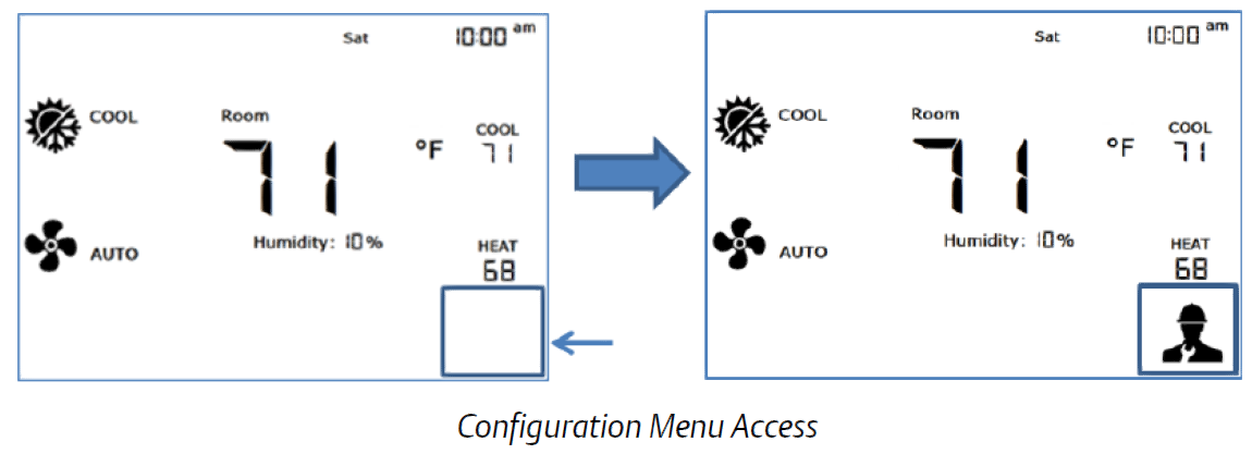
On the first start-up of the thermostat, the default System Configuration is idle. This means that the first step to get the device started is to configure the appropriate system configuration. The following menu will appear by default upon the first startup:
To access the Configuration Menu press the technician icon for 10 seconds. If the thermostat has been previously configured, to access the configuration menu from the main display, a technician icon should be displayed on the right bottom corner of the screen. The technician icon is not displayed automatically. To display the technician icon, touch on the right-bottom corner of the screen, and then press the technician icon for 10 seconds.
Modbus Device Address
The first configuration menu allows users to change the Modbus device address. Ad is shown on the right side of the display to indicate which parameter is being changed (Ad stands for Address). To change the value, press either the up or down arrow, and then press the check icon to go to the next parameter. Press CA to cancel and exit the configuration menu without saving any changes. To change values, touch either the up or down arrow, and then touch the check icon to go to the next parameter.
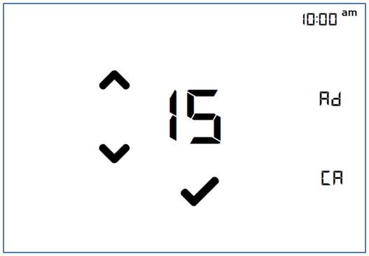
| Address Number | Modbus Device Address |
| 1 to 247 | Range from 1 to 247 |
Modbus Device Baud Rate
The second configuration menu allows users to change the Modbus device baud rate. “br” is shown on the right side of the display to indicate which parameter is being changed (br stands for Baud Rate). To change the value, press either the up or down arrow, and then press the check icon to go to the next parameter. Press CA to cancel and exit the configuration menu without saving any changes.
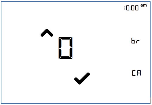
| Menu Option Number | Corresponding Baud Rate |
| 0 | 9600 bps |
| 1 | 19200 bps (default) |
Thermostat System Configuration
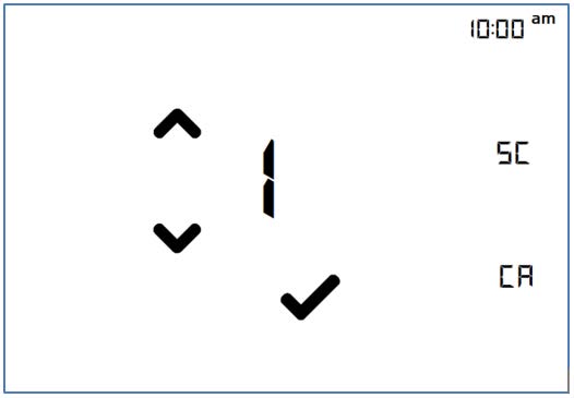
The third configuration menu allows users to set the thermostat system configuration. SC is shown on the right side of the display to indicate which parameter is being changed (SC stands for System Configuration). The current revision of the Emerson Programmable Touchscreen Thermostat supports Conventional HVAC Systems such as RTU and Heat-pump Systems using a reversing valve. There are 4x possible configurations: IDLE, RTU, HP_O and finally HP_B. The first system configuration is IDLE. In this configuration, all the outputs of the thermostats are open and the thermostat controls are inactive. This is to prevent any issues within the current configuration compared to the equipment connected to the thermostat. To change the value, press either the up or down arrow, and then press the check icon to go to the next parameter. Press CA to cancel and return to the normal display without saving any changes.
NOTE: By default, the thermostat is configured as 2 heat-stages and 2 cool-stages thermostat. The number of heating/cooling stages can be changed in the subsequent menus.
When the system is not configured, for example, configured in IDLE, all other configurations are accessible through the menu as below:
| Menu Option Number | Corresponding Baud Rate |
| 0 | IDLE |
| 1 | RTU (Conventional Systems) |
| 2 | *HP_O (Heat-pump with O as reversing signal) |
| 3 | *HP_B (Heat-pump with B as reversing signal) |
When the system is already configured in RTU, HP_O or HP_B, only the IDLE and the current configuration are accessible through the menu:
| Menu Option Number | Corresponding Baud Rate |
| 0 | IDLE |
| (1, 2, or 3) | Current Configuration |
IMPORTANT! In order to change the thermostat’s configuration from a functional configuration (not IDLE) to another one, the thermostat must be set to IDLE configuration first, then all configuration options will be displayed on the screen and the new desired configuration can be chosen.IMPORTANT! A factory reset of all parameters will occur when the system is set to the IDLE configuration, except current date and time that are kept with the use of a Real-Time Clock (RTC).
Number of Heating Stages
For all systems, the number of heating stages can be modified inside this menu. On the screen, the letters “HS” stands for Heating Stages. Possible values are 1 heating stage, 2 heating stages. Press the Done icon to move on to the next menu. Values will not be saved until the last configuration menu is reached.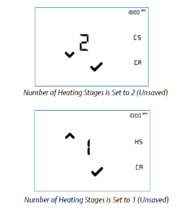
Number of Cooling Stages
For all systems, the number of cooling stages can be modified inside this menu. On the screen, the letters “CS” stands for Cooling Stages. Possible values are 1 cooling stages, 2 cooling stages. Press the Done icon to move on to the next menu. Values will not be saved until the last configuration menu is reached.
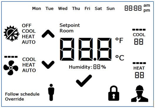
Full Segments Display Test
The fourth configuration menu allows users t o test the full display segments. This allows a complete review of the display segments and to inform the user of all possible segments in the current Emerson Programmable Touchscreen Thermostat revision. Press the check icon to go to the next parameter.
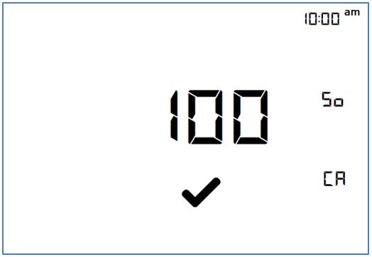
System Revision Display
The fifth and last configuration menu provides the current system revision number. This number is shown with three digits. Note that there is no decimal after the first digit, but the revision number contains a decimal. For example, revision number 100 on the display = 1.00. The software revision will be updated for the latest official release, and will likely be higher than 1.00. Touch the letters “CA” to cancel any previous changes and go back to the normal display without saving. Press the check icon to terminate the configuration menus.
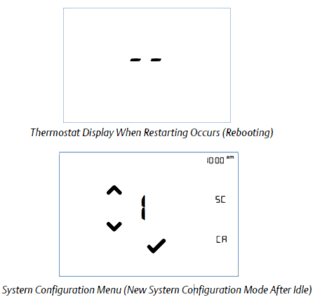
IMPORTANT! If at least one of those parameters has been changed, the thermostat will reboot: Thermostat system configuration, number of Heating stages or number of Cooling stages.Prior to device restart, the display will show “- -” to indicate that the device is about to reboot. When the device is rebooting, the display will turn off for approximately a few seconds until reboot operation has completed.
E2 New Installation and Uploading of Touch_TStat Description File to E2
The Programmable Touchscreen Thermostat (P/N 810-1600) requires adding a description file (P/N 527-0729) to E2. Contact Customer Service to obtain this information: [email protected]
NOTE: Ultrasite32 Software must be installed to perform a description file upload.
- Connect to E2 using UltraSite32 (refer to the UltraSite32 Manual P/N 026-1002).
- Launch the UltraSite program and log in.
- Double-click to UltraSite to view Directory Level and Site Level.
- Right-click on Site Level and click Connect.
- Double-click on Site Level and locate the E2 Unit where the Touch T-Stat.dsc will be installed.
- Right-click on the unit and select Upload Description File.
- Click Browse and select the appropriate description (*.dsc) file for Touch T-Stat.dsc from the computer and click Open.
- Click Upload. A window will display that the description file was successfully imported. Click OK. The description (*dsc) file should appear in the list.
- Once completed, disconnect from the E2 and reboot the E2 controller – either manually with the toggle switch or remotely through Terminal Mode.
NOTE: DO NOT omit the step of rebooting the controller.
Device and COM Port Setup in E2
Modbus Device Setup
Site SupervisorDevice and COM Port Setup in Site Supervisor
Modbus Device Setup
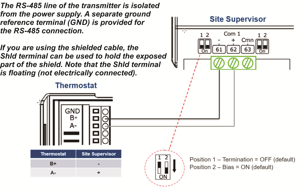
NOTE: The polarity of the MODBUS connection between Site Supervisor and Touchscreen Thermostat is reversed.
Site Supervisor COM Port Setup
- Click the Settings icon (the gear) and select General System Properties.
- Select the Com Port the device is wired to (Com Port 1 – 4).
- Select the available Modbus (Modbus-01 – Modbus-04).
- Set the Modbus connection as follows:> Com Port Baud: 19.2 Kbaud> Com Port data size: 8> Com Port Parity: None> Com Port Stop Bits: 1
- Click Save to save the changes
Installing the Thermostat in Site Supervisor
Installing the Thermostat Application
- Click the Control Inventory icon (the box)
- Expand the HVAC category and go to the Add Control drop-down list and select Touch T-Stat.
Commissioning the Thermostat
- Click the Port ID drop-down list to select Modbus assigned to the Com Port selected.
- Click the Address drop-down list to select the Modbus Address (default address is 1).
- Click the Association drop-down list to select the HVACZone to associate with the thermostat.
- Click Update to save settings.
- Wait a few seconds and the device should appear Online.
- Click the name of the application to view the Status Screen.
This document may be photocopied for personal use.Visit our website at http://www.climate.emerson.com for the latest technical documentation and updates.Join Emerson Technical Support on Facebook http://on.fb.me/WUQRntFor Technical Support call 770-425-2724 or email [email protected]The contents of this publication are presented for informational purposes only and they are not to be construed as warranties or guarantees, express or implied, regarding the products or services described herein or their use or applicability. Emerson Climate Technologies Retail Solutions, Inc. and/or its affiliates (collectively “Emerson”), reserves the right to modify the designs or specifications of such products at any time without notice. Emerson does not assume responsibility for the selection, use or maintenance of any product. Responsibility for proper selection, use and maintenance of any product remains solely with the purchaser and end-user.Emerson is a trademark of Emerson Electric Co. ©2020 Emerson Climate Technologies Retail Solutions, Inc. All rights reserved.

References
[xyz-ips snippet=”download-snippet”]