EMERSON AE4-1302 R10 K4 Refrigeration Copeland Scroll Compressors 7.5 – 15 Horsepower

Safety Instructions
Copeland Scroll™ compressors are manufactured according to the latest U.S. and European Safety Standards. Particular emphasis has been placed on the user’s safety. Safety icons are explained below and safety instructions applicable to the products in this bulletin are grouped on Page 4. These instructions should be retained throughout the lifetime of the compressor. You are strongly advised to follow these safety instructions.
ELECTRICAL SHOCK HAZARD
- Disconnect and lock out power before servicing.
- Discharge all capacitors before servicing.
- Use compressor with grounded system only.
- Molded electrical plug must be used when required.
- Refer to original equipment wiring diagrams.
- Electrical connections must be made by qualified electrical personnel.
- Failure to follow these warnings could result in serious personal injury.
PRESSURIZED SYSTEM HAZARD
- System contains refrigerant and oil under pressure.
- Remove refrigerant from both the high and low compressor side before removing compressor.
- Never install a system and leave it unattended when it has no charge, a holding charge, or with the service valves closed without electrically locking out the system.
- Use only approved refrigerants and refrigeration oils.
- Personal safety equipment must be used.
- Failure to follow these warnings could result in serious personal injury.
BURN HAZARD
- Do not touch the compressor until it has cooled down.
- Ensure that materials and wiring do not touch high temperature areas of the compressor.
- Use caution when brazing system components.
- Personal safety equipment must be used.
- Failure to follow these warnings could result in serious personal injury or property damage.
COMPRESSOR HANDLING
- Use the appropriate lifting devices to move compressors.
- Personal safety equipment must be used.
- Failure to follow these warnings could result in personal injury or property damage.
Safety Statements
- Refrigerant compressors must be employed only for their intended use.
- Only qualified and authorized HVAC or refrigeration personnel are permitted to install commission and maintain this equipment.
- Electrical connections must be made by qualified electrical personnel.
- All valid standards and codes for installing, servicing, and maintaining electrical and refrigeration equipment must be observed.
- IntroductionThe Copeland Scroll™ refrigeration compressor product offering has expanded into the higher horsepower ranges. The scope of this bulletin will cover the application parameters unique to the new models.
- NomenclatureThe Copeland Scroll model numbers include the nominal capacity at the standard 60 Hertz “ARI” rating conditions. Please refer to product literature for model number details.A list of Scroll compressor models covered in this bulletin is depicted in Table 2.
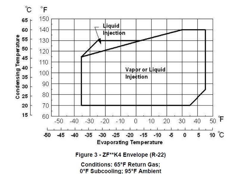
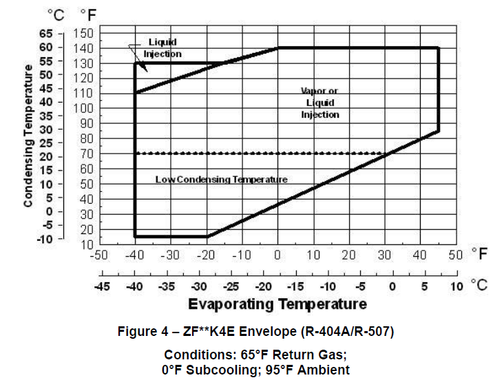
- Operating EnvelopeThese Copeland Scroll models can also be used with a variety of refrigerants. Table 1 at the end of this bulletin shows the selection optionsThe operating envelopes are depicted in Figure 3, Figure 4, Figure 5 and Figure 6 at the end of this bulletin. See Oil Type section for recommended lubricants.
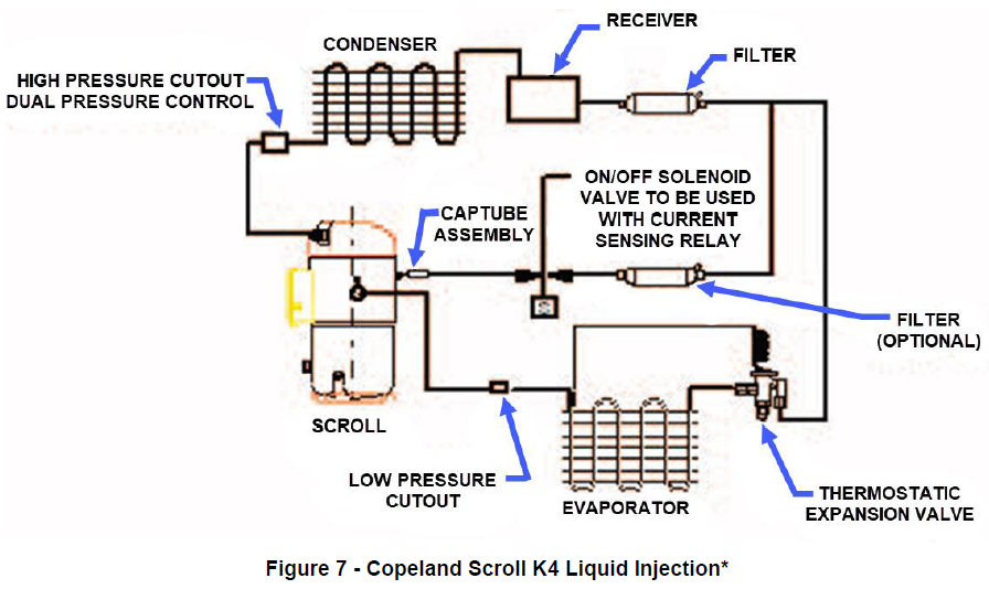
- Liquid or Vapor InjectionThe low temperature models are provided with an injection port that can be used for either liquid or vapor injection. Schematics are shown in Figure 7. The requirements are outlined below:
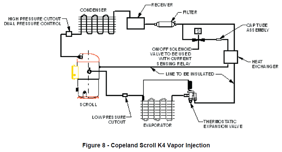
- Capillary Tube – Liquid must be fed through an appropriately sized capillary tube as defined in Table 1. The vapor injection method, in addition to the capillary tube, will require an external heat exchanger (Refer to Figure 8).
- Solenoid Valve – A solenoid valve with a minimum 0.109 inch orifice must be provided in the injection circuit that opens whenever the compressor is operative or cooling is required during pumpdown. The solenoid must be closed when the compressor is cycled off. Failure to provide the solenoid valve can result in liquid refrigerant completely filling the Scroll during an “off-cycle”. If power is reapplied in this condition, the hydraulic effect produced could result in pressure high enough to cause permanent damage to the compressor. Due to this, it is a condition of warranty that the capillary tube and solenoid valve, properly installed, be provided whenever liquid or vapor injection is used.The following components are not required, but they are recommended for liquid injection.
- Sight Glass – A sight glass should be installed just before the capillary tube inlet to allow visual inspection for the presence of liquid refrigerant.
- Filter/Drier – A filter/drier should be installed in the injection circuit to avoid the possibility of capillary tube blockage due to contaminants.Figure 7 and Figure 8 are a representation of typical systems depicting the location of these components.The advantage of this type of injection system is that it tends to self-regulate i.e., as the pressure differential across the capillary tube increases, the amount of liquid fed to the compressor also increases. Since more cooling is needed at high compression ratio conditions, this “automatic” increase in liquid feed is exactly what is needed.For the liquid injection system to be effective, a minimum of 5°F subcooled liquid at the capillary inlet is required. However, do not use mechanically cooled liquid refrigerant, such as found on supermarket rack applications. The cap tube will be oversized and may result in feeding too much refrigerant into the scrolls. This condition can dilute the oil in the crankcase and cause lubrication issues.
- AccumulatorsDue to our Copeland Scroll compressor’s inherent ability to handle liquid refrigerant in flooded start and defrost operation conditions, accumulators may not be required. An accumulator is required on single compressor systems with charges over 17 lbs. On systems with defrost schemes or transient operations that allow prolonged, uncontrolled liquid return to the compressor, an accumulator is required unless a suction header of sufficient volume to prevent liquid migration to the compressor is used.
- Superheat RequirementsIn order to assure that liquid refrigerant does not return to the compressor during the running cycle, attention must be given to maintaining proper superheat at the compressor suction inlet. Emerson recommends a minimum of 20°F (11°C) superheat, measured on the suction line 6 inches (152mm) from the suction valve, to prevent liquid refrigerant floodback.Another method to determine if liquid refrigerant is returning to the compressor is to accurately measure the temperature difference between the compressor oil crankcase and the suction line. During continuous operation we recommend that this difference be a minimum of 50°F (27°C). This “crankcase differential temperature” requirement supersedes the minimum suction superheat requirement in the last paragraph. To measure oil temperature through the compressor shell, place a thermocouple on the bottom center (not the side) of the compressor shell and insulate from the ambient.
During rapid system changes, such as defrost or ice harvest cycles, this temperature difference may drop rapidly for a short period of time. When the crankcase temperature difference falls below the recommended 50°F (27°C), our recommendation is the duration should not exceed a maximum (continuous) time period of two minutes and should not go lower than a 25°F (14°C) difference.Contact your Emerson Climate Technologies representative regarding any exceptions to the above requirements.
- Crankcase HeatCrankcase heaters (See Table 4) are required, on outdoor systems, when the system charge exceeds 17 lbs.The crankcase heaters listed on Table 4 are intended for use only where there is limited access. The heaters are not equipped for use with electrical conduit. Where applicable electrical safety codes require heater lead protection, a crankcase heater terminal box should be used. Recommended crankcase heater terminal cover and box numbers are listed in Table 5. If there are any questions concerning their application, contact the Emerson Climate Technologies Application Engineering Department.
- Discharge Line ThermostatA discharge line thermostat is not required on these models. The compressor features an internal temperature sensor which works in conjunction with the protection module and will shut the compressor off if high discharge temperatures exist.
- Pressure ControlsBoth high and low pressure controls are required. See Table 6 for the minimum and maximum set points.
- IPR ValveThere is no internal pressure relief valve in these larger horsepower scrolls. Therefore, a high pressure control located prior to any shut-off valves is mandatory. There is an access port located on the compressor discharge Rotalock fitting to accommodate this control.
- Motor ProtectionThere are five PTC (Positive Temperature Coefficient) internal thermistors connected in series that react with avalanching resistance in the event of high temperatures.Four of the thermistors are used to sense motor temperatures, and the fifth is used as a discharge temperature sensor. The thermistor circuit is connected to the protector module terminals S1 and S2.When any thermistor reaches a limiting value, the module interrupts the control circuit and shuts off the compressor. After the thermistor has cooled sufficiently, it will reset. However, the module has a 30 minute time delay before reset after a thermistor trip.
- ProgrammableIf the INT69SCY (071-0597-00) module is applied in conjunction with a Programmable Logic Controller, it is important that a minimum load is carried through the M1-M2 control circuit contacts.The minimum required current through the module relay contacts needs to be greater than 100 milliamps but not to exceed 5 amps. If this minimum current is not maintained, this has a detrimental effect upon the long-term contact resistance of the relay and may result in false compressor trips.PLC operated control circuits may not always provide this minimum current. In these cases modifications to the PLC control circuit are required. Consult your Application Engineering Department for details.
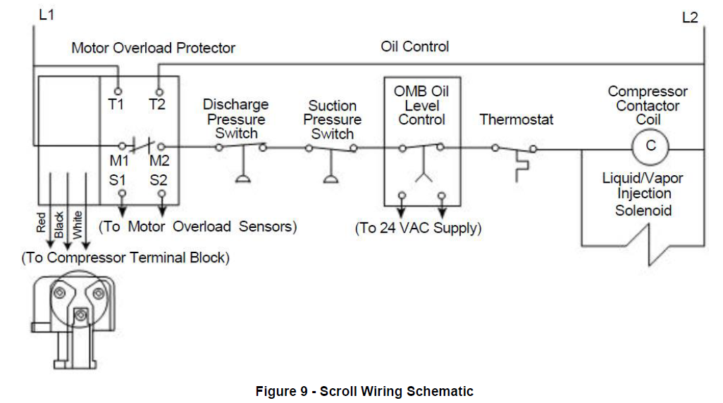
- Phase ProtectionThe INT69-SCY module provides phase protection for the compressor. The module senses the correct phase sequence, phase loss and voltage sag for each leg (L1, L2 and L3) of the incoming power supplied to the compressor. At installation the three phases of the power supply must be wired in the correct 120° phase sequence. This will ensure the compressor will start and operate in the correct clockwise direction.The INT69-SCY module trips (M1-M2 contacts open) when the module senses a phase loss. There is a 5 minute time delay before the module attempts a restart. If all three phases are present, then the module will reset (M1-M2 contacts will close) and the compressor will start and run. If not, the module will attempt a restart after another 5 minute time delay. After 10 failed attempts to restart, the module will lock-out (M1-M2 contacts will remain open) and can only be reset by removing the power from T1-T2 for a minimum of 5 seconds.
The INT69SCY is intended to protect the compressor. The L1/L2/L3 and S1/S2 leads are pre-wired on the compressor and are engineered to work in conjunction with the motor protector module. The module leads should not be moved or extended because of the possibility of inducing electronic noise into the INT69SCY, which could cause false trips of the module. Refer to Figure 9 for wiring schematic details. Also, see the Module and Sensor Functional Check section for proper operation procedures.
- Module and Sensor Functional CheckThe following field troubleshooting procedure can be used to evaluate the solid state control circuit:Refer to Table 8 for a technical data summary.
- Module Voltage Supply Troubleshooting
- Verify that all wire connectors are maintaining a good mechanical connection. Replace any connectors that are loose.
- Measure the voltage across T1-T2 to ensure proper supply voltage.
- Determine the control voltage by using a voltmeter and then measure the voltage across the M1-M2 contacts:
- If the measured voltage is equal to the control volts then the M1-M2 contacts are open.
- If the measurement is less than 1 volt and the compressor is not running, then the problem is external to the INT69-SCY module.
- If the voltage is greater than 1 volt but less than the control voltage, the module is faulty and should be replaced.
- Use an Ohmmeter with a maximum of 9 VDC for checking – do not attempt to check continuity through the sensors with any other type of instrument. Any external voltage or current may cause damage requiring compressor replacement.
- During normal operation, this resistance value should read less than 4500 ohms ±20%.
- If the M1-M2 contacts are open, the measured S1-S2 value is above 2750 ohms ±20% and the compressor has been tripped less than 30 minutes then the module is functioning properly.
- If the S1-S2 wire leads read less than 2750 ohms ±20% and the M1-M2 contacts are open, reset the module by removing the power to T1-T2 for a minimum of 5 seconds.
- Replace all wire leads and use a voltmeter to verify the M1-M2 contacts are closed.If the M1-M2 contacts remain open and S1-S2 are less than 2500 ohms, remove leads from the M1-M2 contacts and jumper together;
- Compressor
- Remove phase sensing leads from the module from L1/L2/L3.
- Use a voltmeter to measure the incoming 3 phase voltage on L1/L2/L3. WARNING: L1/L2/L3 could be at a potential up to 600VAC.
- Ensure proper voltage on each phase.
- Remove power to the module for a minimum of 5 seconds to reset and replace all wire leads. Re-energize the module. If the M1-M2 contacts are open with proper voltage to T1-T2, L1/L2/L3 and proper resistance to S1-S2 then the module is faulty and should be replaced.
- Oil TypePolyol ester lubricant (POE) must be provided if the Copeland Scroll is to be used with HFC refrigerants. Copeland™ Ultra 22 CC™, Mobil EAL Arctic 22 CC, or ICI EMKARATE RL 32CF are the only polyol ester oils approved by Emerson Climate Technologies at this time.The factory oil charge for all 7.5-15 HP. models is 140 ounces. Field recharge is 135 ounces.Note: Do not add mineral oil to compressors charged with POE oil intended for use with HFC refrigerants. Use only the Emerson approved POE lubricants for these applications.POE may cause an allergic skin reaction and must be handled carefully and the proper protective equipment (gloves, eye protection, etc.) must be used when handling POE lubricant. POE must not come into contact with any surface or material that might be harmed by POE, including without limitation, certain polymers (e.g. PVC/ CPVC and polycarbonate). Refer to the Safety Data Sheet (SDS) for further details.
- Oil Management for Rack ApplicationsCopeland™ refrigeration scrolls may be used on multiple compressor parallel rack applications. This requires the use of an oil management system to maintain proper oil level in each compressor crankcase. The sight glass connection supplied can accommodate the mounting of the oil control devices.Unlike Semi-Hermetic compressors, Scrolls do not have an oil pump with accompanying oil pressure safety controls. Therefore, an external oil level control is required.The OMB/C Oil Level Management Control combines the functions of level control and timed compressor shut-off should the level not come back to normal within a set period of time. This device has been found to provide excellent performance in field tests on Scroll compressors and is recommended for parallel system applications. Refer to Table 7 for proper Adapter option.
Immediately after system start-up the oil reservoir level will fluctuate until equilibrium is reached. It is advisable to monitor the oil level during this time to assure sufficient oil is available. This will prevent unnecessary trips of the oil control system.Note: If oil management problems are occurring please refer to AE 17-1320 or contact the Emerson Climate Technologies Application Engineering Department.Note: ZB50, 58, 66, 76, 88 are not approved for rack applications due to compressor limitations.For Technical details about OMB/C Oil Level Management Control follow these links below:Instruction SheetInstallation Instruction Sheet

- Discharge MufflersGas flow through scroll compressors is continuous with relatively low pulsation. External mufflers applied to piston compressors will probably not be required on Copeland Scrolls. Due to system variability individual tests should be conducted by the system manufacturer to verify acceptable levels of sound and vibration.
- Compressor MountingCompressor mounting must be selected based on application. Consideration must be given to sound reduction and tubing reliability. Some tubing geometry or “shock loops” may be required to reduce vibration transferred from the compressor to external tubing.
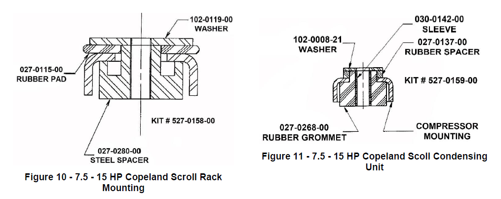
- Mounting for Rack SystemsSpecially designed steel spacers and rubber isolator pads are available for Copeland Scroll 7.5-15 H.P. scroll rack applications. This mounting arrangement limits the compressors motion thereby minimizing potential problems of excessive tubing stress. Sufficient isolation is provided to prevent vibration from being transmitted to the mounting structure. This mounting arrangement is recommended for multiple compressor rack installations. See Figure 10 for a detail of this mounting system.Note: The use of standard soft grommets is not recommended for Copeland Scroll rack installations. These “softer” mounts allow for excessive movement that will result in tube breakage unless the entire system is properly designed.
- Condensing Units- For 7.5-15 H.P.Copeland Scroll condensing unit applications soft mounts are recommended. See Figure 11.
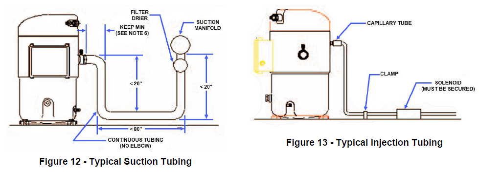
- Tubing ConsiderationsProper tube design must be taken into consideration when designing the tubing connecting the scroll to the remaining system. The tubing should provide enough “flexibility” to allow normal starting and stopping of the compressor without exerting excessive stress on the tube joints. In addition, it is desirable to design tubing with a natural frequency away from the normal running frequency of the compressor. Failure to do this can result in tube resonance and unacceptable tubing life. Figure 12 and Figure 13 are examples of acceptable tubing configurations.CAUTION: These examples are intended only as guidelines to depict the need for flexibility in tube designs. In order to properly determine if a design is appropriate for a given application, samples should be tested and evaluated for stress under various conditions of use including voltage, frequency, and load fluctuations, and shipping vibration. The guidelines above may be helpful; however, testing should be performed for each system designed.
- Connection FittingsLarger horsepower Copelnd Scroll compressors are supplied with Rotalock adapter spuds welded on the shell. The fitting sizes for 7.5 through 15 H.P. scrolls are as follows:
- Three Phase Scroll Compressors Directional DependenceScroll compressors are directional dependent; i.e. they will compress in one rotational direction only. Three phase scrolls will rotate in either direction depending on power phasing. Since there is a 50/50 chance of connected power being “backwards”, contractors should be warned of this. Appropriate instructions or notices should be provided by the OEM. To eliminate the possibility of reverse rotation a Copeland Phase Control line monitor, P/N 085-0160-00, or other phase monitor is recommended on installations not using the phase sensing module. However, our newer modules will prevent operation in the wrong direction. Refer to Table 8 for module features.Verification of proper rotation can be made by observing that the suction pressure drops and the discharge pressure rises when the compressor is energized. Additionally, if operated in reverse the compressor is noisier and its current draw is substantially reduced compared to tabulated values.No time delay is required on three phase models to prevent reverse rotation due to brief power interruptions.
- Deep Vacuum OperationDo not run a Copeland Scroll compressor in a deep vacuum. Failure to heed this advice can result in arcing of the Fusite pins and permanent damage to the compressor.A low pressure control is required for protection against deep vacuum operation. See Pressure Controls section for proper set points. (Table 6)Scroll compressors (as with any refrigerant compressor) should never be used to evacuate a refrigeration or air conditioning system. See AE24-1105 for proper system evacuation procedures.
- Unbrazing System ComponentsIf the refrigerant charge is removed from a Scroll unit by bleeding the high side only, it is sometimes possible for the scrolls to seal, preventing pressure equalization through the compressor. This may leave the low side shell and suction line tubing pressurized. If a brazing torch is then applied to the low side, the pressurized refrigerant and oil mixture could ignite as it escapes and contacts the brazing flame. It is important to check both the high and low sides with manifold gauges before unbrazing or in the case of assembly line repair, remove refrigerant from both the high and low sides. Instructions should be provided in appropriate product literature and assembly (line repair) areas.
- High Potential (Hipot) TestingMany of the Copeland brand compressors are configured with the motor below the compressor. As a result when liquid refrigerant is within the compressor shell the motor can be immersed in liquid refrigerant to a greater extent than with compressors with the motor mounted above the compressor. When Copeland brand compressors are Hipot tested and liquid refrigerant is in the shell, they can show higher levels of leakage current than compressors with the motor on top because of the higher electrical conductivity of liquid refrigerant than refrigerant vapor and oil. This phenomenon can occur with any compressor when the motor is immersed in refrigerant. The level of current leakage does not present any safety issue. To lower the current leakage reading the system should be operated for a brief period of time to redistribute the refrigerant to a more normal configuration and the system Hipot tested again. See bulletin AE4-1294 for Megohm testing recommendations. Under no circumstances should the Hipot or Megohm test be performed while the compressor is under a vacuum.Note: The solid state electronic module components and internal sensors are delicate and can be damaged by exposure to high voltage. Under no circumstances should a high potential test be made at the sensor terminals or sensor leads connected to the module. Damage to the sensors or module may result.
- Copeland Scroll Functional CheckCopeland Scroll compressors do not have internal suction valves. It is not necessary to perform functional compressor tests to check how the compressor will pull suction pressure. This type of test may damage a Scroll compressor. The following diagnostic procedure should be used to evaluate whether a Copeland Scroll compressor is functioning properly.
- Verify proper unit voltage.
- Normal motor winding continuity and short to ground checks can be used to determine proper motor resistance or if an internal short to ground has developed.
- With service gauges connected to the suction and discharge pressure fittings, turn on the compressor. If suction pressure falls below normal levels the system is either low on charge or there is a flow blockage.
- If the suction pressure does not drop and the discharge pressure does not rise, reverse any two of the compressor power leads and reapply power to verify the compressor was not wired to run in the reverse direction.The operational compressor current draw should be compared to published performance curves at the operating conditions (pressures and voltages). Significant deviation (± 15%) from published values may indicate a faulty compressor.
- General Guidelines and More InformationFor general Copeland Scroll compressor please log in to Online Product Information at Emerson.com/OPI, refer to the Application Engineering bulletins listed below, or contact your Application Engineer.Note: The ZF can operate as a ZS by capping the injection port.

 Note: The ZF can operate as a ZS by capping the injection port.

Notes:
- The above tubing configurations are guidelines to minimize tube stress.
- Follow similar guidelines for discharge tubing and oil return tubing as needed.
- If a run over 30” is required, intermediate clamps may be necessary.
- Do not hang weights on tubing (e.g. filter drier on suction tubing) except after clamps or close to the header.
- Tube runs of less than 12” are not recommended.
- This dimension should be made as short as possible but still insuring a proper braze joint.
- The above tubing recommendations are based on “no elbow joints”. The use of continuous tubing is preferred.
Table 1 – Refrigerants and Lubricants
| Model | Refrigerant | Lubricant |
| ZF, ZS | R-22 | MO |
| ZF, ZS | R-404A, R-507, R-22 | POE |
Table 2 – ZS and ZF compressor models from 7.5 HP to 15 HP
| ZS models | ZF models |
| ZS56K4*, ZS75K4* and ZS92K4* | ZF24K4*, ZF33K4*, ZF40K4* and ZF48K4* |
Table 3 – Capillary Tubes for Liquid or Vapor Injection
|
Model |
Cap Tube | Emerson Kit Number | Legacy Emerson Kit Number* | |
| I.D
(inches) |
Lenght (inches) | |||
| R-22 | ||||
| ZF24K4 | 0.05 | 5″ | 998-1873-00 | 998-1586-00 |
| ZF33K4 | 0.05 | 5″ | 998-1873-00 | 998-1586-00 |
| ZF40K4 | 0.07 | 30″ | 998-1873-04 | 998-1586-05 |
| ZF48K4 | 0.07 | 10″ | 998-1873-05 | 998-1586-06 |
| R-404A/R-507 | ||||
| ZF24K4E | 0.05 | 30″ | 998-1873-03 | 998-1586-04 |
| ZF33K4E | 0.05 | 17.5″ | 998-1873-01 | 998-1586-01 |
| ZF40K4E | 0.07 | 30″ | 998-1873-04 | 998-1586-05 |
| ZF48K4E | 0.07 | 30″ | 998-1873-04 | 998-1586-05 |
| R-134A | ||||
| ZF24K4E | 0.05 | 17.5″ | 998-1873-01 | 998-1586-01 |
| ZF33K4E | 998-1873-02 | 998-1586-02 |
Table 4 – External Wrap-Around Crankcase Heater Numbers*
| Part. No | Volts | Watts | Lead Lengths (in) | Ground Wire Lengths (in) |
| 018-0036-01 | 120 | 70 | 21 | 29 |
| 018-0036-00 | 240 | 70 | 21 | 29 |
| 018-0036-02 | 480 | 70 | 21 | 29 |
| 018-0036-03 | 575 | 60 | 21 | 29 |
Table 5 – Conduit Ready Terminal Box Numbers
| Model | Item | Part Number |
| 7.5-15 H. P. | Cover | 005-7061-00 |
| 7.5-15 H.P. | Box | 062-7015-00 |
Table 6 – Pressure Control Settings
| Application | Control Type | R-404A/ R507 | R-22 |
| Medium Temp. (ZF) | Low | 8 PSIG Min. | 10 PSIG Min. |
| High | 445 PSIG Max. | 381 PSIG Max. | |
| Medium Temp. (ZS) | Low | 8 PSIG Min. | 24 PSIG Min. |
| High | 445 PSIG Max. | 381 PSIG Max. | |
| Low Temp. (ZF) | Low | 0 PSIG Min. | 2 in. Hg Min. |
| High | 400 PSIG Max. | 335 PSIG Max. |
Table 7 – Mounting Adapter Kit for OMB/C Oil Management Control
| Kit Description | Compressor Type | PCN | Recommended Torque Adapter to Compressor | Drawing |
| 3/4″-NPTF
Screw Adapter |
Copeland Scroll
1.5 – 9 HP ZF, ZS, ZB |
065668
OMB-ACA |
30 – 40 ft – lbs | |
| 1 1/4″ –
12UNF Rotalock Adapter |
Copeland Scroll
1.5 – 9 HP ZF, ZS, ZB |
P/N 066650
(KS30394- 2) OMB-ACF |
80 ft – lbs |
Table 8 – Technical Data Summary
| Emerson P/N Manufacture P/N | 071-0520-07
T.I. 30AA201E |
071-0520-05
Kriwan 69SC-DV |
071-0597-00
Kriwan 69SCY |
| T1-T2 Module Power | |||
| Voltage Supply Frequency | 120V & 240V
50Hz 60 Hz |
120V & 240V
50Hz 60 Hz |
120V & 240V
50Hz 60 Hz |
| M1-M2 Module Output Contacts | |||
| Maximum Voltage Maximum Current Minimum Current Relay Output Power Output | N/A
5 Amps 100 milliamps 2.5 A, 600 V < 5.5 VA |
250 VAC
5 Amps 100 milliamps 5 A, 300 V < 3 VA |
250 VAC
5 Amps 100 milliamps 5 A, 300 V < 3 VA |
| S1-S2 Thermal Protection | |||
| Trip Out Resistance Reset Resistance
Reset Time Manual Reset |
N/A N/A
30 min ± 5min. T1-T2 interrupt for minimum of 5 sec |
4500/ ± 20%
2750/ ± 20% 30 min ± 5min. T1-T2 interrupt for minimum of 5 sec |
4500/ ± 20%
2750/ ± 20% 30 min ± 5min. T1-T2 interrupt for minimum of 5 sec |
| L1-L2-L3 Phase Monitoring | |||
| Phase Sensor Phase Monitoring Circuit Rating Trip Delay Lockout
Reset for Lockout |
Non Phase Sensing Non Phase Sensing
Non Phase Sensing Non Phase Sensing Non Phase Sensing |
Non Phase Sensing Non Phase Sensing
Non Phase Sensing Non Phase Sensing Non Phase Sensing |
3
3 AC 50/60Hz 120V to 632V
5 min delay before restart attempt After 10 module trips T1-T2 interrupt for minimum of 5 sec |
The contents of this publication are presented for informational purposes only and are not to be construed as warranties or guarantees, express or implied, regarding the products or services described herein or their use or applicability. Emerson Climate Technologies, Inc. and/or its affiliates (collectively “Emerson”), as applicable, reserve the right to modify the design or specifications of such products at any time without notice. Emerson does not assume responsibility for the selection, use or maintenance of any product. Responsibility for proper selection, use and maintenance of any Emerson product remains solely with the purchaser or end user.
![]()
References
[xyz-ips snippet=”download-snippet”]