EMERSON CC200 Controller Hardware and Wiring

Functions of the CC200
- Low, medium, and dual temperature case types supported.
- Stepper Valve Driver Onboard.
- EEPR control based on pressure or temperature.
- New patent pending floating evaporator SST setpoint management automatically adjusts evaporator SST to the optimum setpoint for discharge air.
- Case Display with touchscreen.
- Form C relays allow direct control of case loads and simplified wiring.
- Simplified wiring and connections reduce labor and setup time.
- Bluetooth® connectivity for easy controller status and service.
CC200 Main Controller Specifications
| Name | Description |
| Power Requirement | 24VDC 71(Earth) – 72(+) – 73(-) |
| Mounting | DIN Rail |
| Dimensions | 7 3/16″x 4 5/16″x 3″ (W x H x D) |
|
Serial Port |
Master/slave, 1/8 load, up to 115.2K Baud, isolated; generic 150-ohm termination with switch. 3-Terminal connector with onboard 100-ohm between RS485 “C” Terminal and RS485 isolated ground to allow direct earth ground connection. The RS485 Port B Gnd is isolated from RS485 Port A Gnd and all other circuit and earth grounds. |
| ETH1 ETH2 | BACnet TCP/IP repeater (Ethernet 10/100) BACnet TCP/IP repeater (Ethernet 10/100) |
| Operating Temperature | 14°F to 122°F (-10°C to 50°C) |
| Relative Humidity | 20-85% RH; non-condensing |
Power Supply Wiring and Specifications
| Power Supply Specifications | |
| Primary Power | 120VAC |
| Secondary Power | 24VDC |
| CC200 Power Requirement | 24VDC 60W |
| Required Power Supply | CC200 Power Supply
24VDC 60W Emerson P/N 810-3182 |
| Power Supply Terminals | 2 (-V) & 3 (+V) |
| CC200 Power Terminals | 72(+) –73(-) — 71(Earth) |
| Wire Spec | 16AWG |
| 24VDC Max Wire Length | 20” |
| Mounting | DIN Rail Mounted |
| Power Supply Dimensions | 2.06” x 3.54” x 2.14” (W x H x D) |
Step 1: Mount Power Supply and CC200 Main Controller to DIN Rail.Step 2: Wire Secondary power from Power Supply to CC200 Main Controller.a. Reference specification and drawing for Terminals.b. This is Polarity Sensitive.Step 3: Wire Primary power to Power Supply.a. Reference the specification and drawing for Terminals.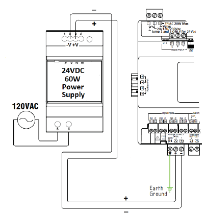
CC200 Main Controller Output Wiring
Note: Fan motors over 5 amps must use the alternate wiring method with a pilot device between CC200 and the motor
Step 1: Verify power is OFF on the CC200 Main Controller.Step 2: Refer to the specification drawing below for the correct termination terminals and how to wire:
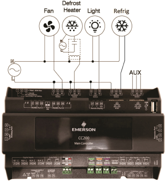
For Fan Motors Over 5A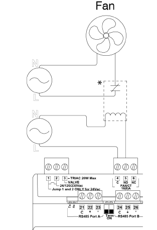
CC200 Main Controller Output Specifications
| Relay Specifications | |||
|
CC200 Label |
AMP/VAC |
LOADS CONTROLLED |
TERMINALS |
|
Fan/CT |
Form C Relay with built in CT:
NO: Resistive 5A, 240Vac or less; 5FLA, 30LRA, 240Vac or less; Pilot Duty B300 NC: Resistive 5A, 240Vac or less; 5FLA, 30LRA, 240Vac or less; Pilot Duty C300 |
Evap Fans |
4(C) – 5(NO) – 6 (NC) |
| Defrost | Form C Relay
NO: Resistive 12A, 240Vac or less; 10FLA, 60LRA, 240Vac or less; Pilot Duty B300 NC: Resistive 12A, 240Vac or less; 5FLA, 30LRA, 240Vac or less; Pilot Duty C300 |
Defrost Heaters | 7(C) – 8(NO) – 9(NC) |
| Light | Case Lights | 10(C) – 11(NO) – 12(NC) | |
| Refrig | LLSV | 13(C) – 14(NO) – 15(NC) | |
|
AUX Relay |
Alarm Out, Door Alarm, Satellite for E2E control, backup for other RO |
16(C) – 17(NO) – 18(NC) |
|
|
AO1 (AO) |
4-20mA or 0-10VDC |
Satellite for E2E control, future Light Dimming, future Anti– sweat |
39(+) – 40(-) |
| AO2 (AO) | 4-20mA or 0-10VDC | Future Light Dimming | 41(+) – 42(-) |
CC200 Main Controller Input Specifications
| Input Specifications | ||
| CC200 Label | Description | TERMINALS & COLOR |
| DAT | Discharge Air | 46 – 47 Green |
| TERM | Defrost Termination | 48 – 49 Orange |
| RAT | Return Air | 50 – 51 Purple |
| COIL OUT | Coil Out | 52 – 53 |
|
PRESSURE |
100lb Pressure Transducer
Polarity sensitive |
43(0v) – 44(Sig) –
45(+5V) Black – White – Red |
| Def CT Amps | Defrost Amps (electric defrost only) | 54(+) – 55(-) |
| Aux Inputs AI & DI | ||
| AI1 AI2 | Configurable functions: External fan CT, Coil Inlet Temp, Product Temp, Circuit Suction Temp | 56(+) – 57(-)
58(+) – 59(-) |
| DI1 DI2 DI3 DI4 | Door switch, service switch, dual temp switch, defrost term switch, leak shutdown, satellite 1 for E2E, satellite 2 for E2E | 31(DI1) – 32(C)
33(DI2) – 34(C) 35(DI3) – 36(C) 37(DI4) – 38(C) |
| Wire Specifications for extending Input and Valves | |
|
Analog Temp Sensors or Digital Inputs |
General Cable 92454A #22/2 Shielded
Emerson P/N 135–0600 If manufacturer harness must be extended, join wires with heat shrink and solder. |
|
Pressure Transducer |
Belden 28326AS #18/4 Shielded
Emerson P/N 135–2832 If manufacturer harness must be extended, join wires with heat shrink and solder. |
CC200 Input Wiring
Step 1: Make sure the power is OFF to the CC200 Main Controller.Step 2: Determine what sensors will be needed and wire per the specification above.
a. If sensor need to be extended Emerson only supports heat shrink and solder.
Step 3: Determine how many coils are on the cases.a. For multi-coil cases the CC200 supports one sensor per coil for discharge air, return air, defrost termination and coil outlet. Pressure transducers for multi-coil cases may be installed one per coil or one for the entire case (parameter selectable).b. For multi-coil cases the sensors on coil #1 will terminate on the CC200 Main Controller. Second and third sensor coils will require an Expansion Module per coil and each coil’s sensor will terminate on the each of the Expansion Modules.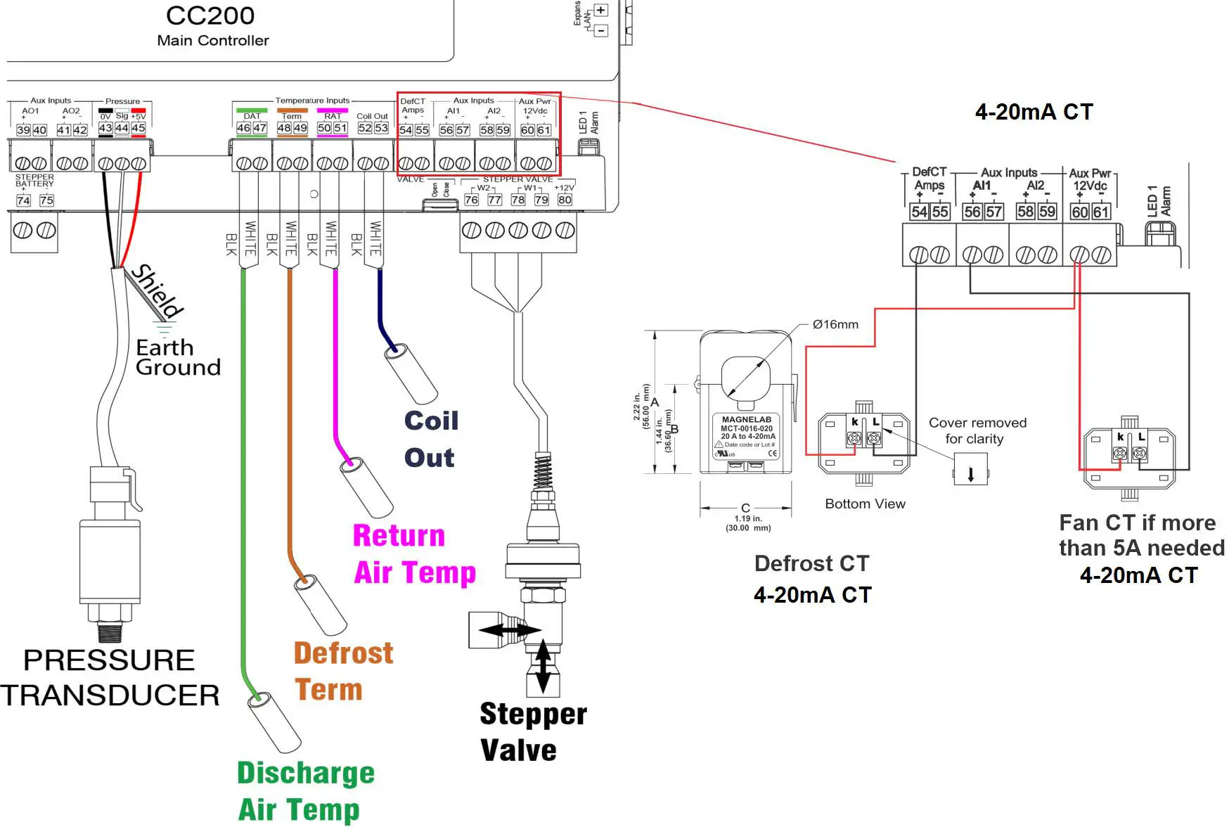
CC200 Stepper Valve Wiring and Specifications
| Stepper Valve (Sporlan CDS Only) | ||
|
Stepper Valve |
Bipolar |
W2 |
| 76(White) – 77(Black) | ||
| W1 | ||
| 78(Red) – 79(Green) | ||
|
Stepper Valve – Expansion Module |
Bipolar |
W2 |
| 33 (White) – 34 (Black) | ||
| W1 | ||
| 35 (Red) – 36 (Green) |
Step 1: Make sure the power is OFF to the CC200 Main Controller.Step 2: The CC200 Case control system (Main Controller + Expansion Modules) supports Electronic Expansion Valve (EEV) control using either Pulse Width Modulation (PWM) valves OR Stepper valves but NOT both.The first case in a CC200 lineup (“a” Case) has support for control of Electronic Evaporator Pressure Regulation (EEPR) stepper valve.
- PWM EEV 1 or Stepper EEV 1 is always located on CC200 Main Controller
- PWM EEV 2 or Stepper EEV 2 is always located on Expansion Module 1
- PWM EEV 3 or Stepper EEV 3 is always located on Expansion Module 2EEPR Location
- When PWM EEV is used, EEPR is always located on CC200 MainController Stepper terminals
- When Stepper EEV is used, EEPR is located on the last Expansion
Module Stepper terminals
a. The wiring specification above is only for the Sporlan CDS and SER valves.b. If other manufacturer valves are used, refer to the manufacturer’s specification and contact Emerson for instructions on how to terminate.
Step 3: Refer to the drawing and specification for termination of the valve: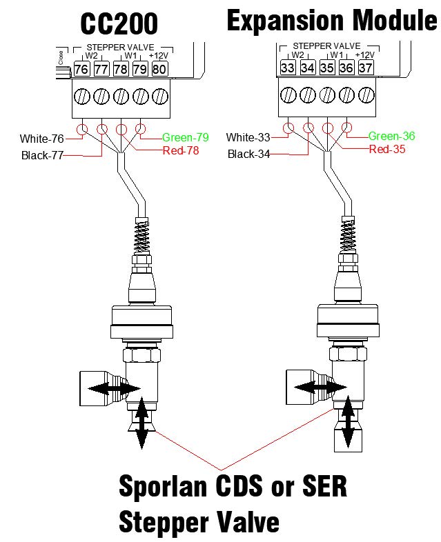
CC200 Expansion Module Wiring and Specifications
| CC200Label | Description | TERMINALS & COLOR |
| DAT | Discharge Air | 16 – 17 Green |
| TERM | Defrost Termination | 18 – 19 Orange |
| RAT | Return Air | 20 – 21 Purple |
| COIL OUT | Coil Out | 22 –23 |
|
PRESSURE |
100lb Pressure Transducer Polarity sensitive | 12(0v) – 13(Sig) – 14(+5V)
Black – White – Red |
| Wire Specs for Extending Inputs and Valves | ||
| Analog Temp Sensors or Digital Inputs | Heat Shrink and Solder
General Cable 92454A #22/2 Shielded. Emerson P/N 135–0600 |
|
|
Pressure Transducer |
Heat Shrink and Solder Belden 28326AS #18/4 Shielded.
Emerson P/N 135–2832 |
|
|
Stepper Valve |
Heat Shrink and Solder
Use the manufacturer harness with a max length not to exceed 30ft (9 meters). Belden 28326AS #18/4 Emerson P/N 135–2832 |
Step 1: Determine if you need an Expansion Module.a. You will add an Expansion for a second or third coil. Each coil will have temp sensors and a transducer and will be wired to the respective Expansion Module.Step 2: Addressing the Expansion Modulea. Set the address of each Expansion Module using the ON/OFF dip switch bank on the top left corner of the hardware (refer to figure below).b. Expansion Module one must be set to address 1, Expansion Module two to address 2, Expansion Module three to address 3.Step 3: Install the Expansion Module.a. Make sure power is OFF to the CC200 Main Controller. Power will be restored in a later step.b. Install Expansion Module 1 on the DIN rail adjacent to the CC200’s right side. The CC200 Expansion port terminal V+ should be aligned with Expansion Module 1 Expansion port terminal V+. Slide the Expansion Module into the CC200Expansion port so both device’s Expansion port connectors fasten together.c. If Expansion Modules 2 and 3 are present, connect to Expansion Module 1’s Expansion port using in the same manner described in the above step. No wiring is needed between the CC200 Main Controller and CC200 ExpansionModule. Power and communication are sourced from the CC200 Expansion port and passed through each Expansion Module Expansion port.Step 4: Terminate sensors on the Expansion Module and refer to the drawing and specifications above for terminal numbers and how to terminate. Once all sensor terminations are complete and the Expansion Module Expansion port is securely plugged into the CC200 Expansion port, restore the 24VDC supply power to the CC200 Main Controller. Once connected, the Expansion Module PWR ON LED will illuminate green indicating supply power is present.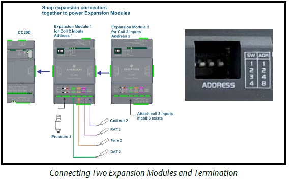
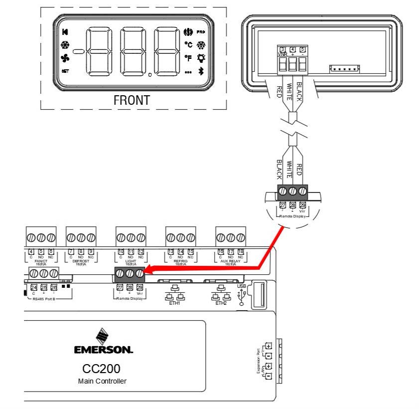
CC200 Case Display
| CC200 Display Specifications | |
| Power Requirement | Powered from the CC200 Case Controller |
| Required Wire | Belden #8771 3C22AWG or Belden #8772 3C22AWG |
| Mounting | Use the white sliding clips that are provided with the CC200 Display |
| Operating Temp | UL: 32°F to 131°F / UL: 0°C to 55°C |
| Relative Humidity | 20 to 85 RH% (non-condensing humidity) |
| Protection | Body: IP20; Front: IP66 |
| Points | CC200 Terminals to CC200 Display Terminals |
| – | 27(-) to 5(-) |
| + | 28(+) to 4(+) |
| VNR | 29(VNR) to 3(VNR) |
Step 1: Make sure power to the CC200 Main Controller is turned OFF.Step 2: Make termination from the CC200 Main Controller to the CC200 Display.a. It is critical that these terminations are made correctly as this can result in damage to both devices if not terminated correctly.b. Clip and insulate shield at both ends of the Belden connection cable. Keep cable length at less than 50 ft (15 meters).Step 3: Power ON the CC200 Main Controller.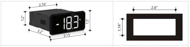
Part Numbers for Ordering
| *Emerson Part Number | Description |
| 810-3180 | CC200 Main Controller |
| 810-3181 | CC200 Expansion Module |
| 810-3182 | CC200 Power Supply 24VDC 60W
Emerson P/N 810–3182 |
| 810-3183 | CC200 Case Display |
| 501-1122 | Discharge Air Temperature Sensor |
| 501-1127 | Defrost Termination Temperature Sensor |
| 501-1128 | Return Air Temperature Sensor |
| 501-1125 (blue)
501-1126 (red) |
Coil Out Temperature Sensor |
| 800-2100 | 100lb Pressure Transducer |
*For optimal performance of the CC200, Emerson parts are required.
Cold Chain Connect is the CC200 mobile application for setting parameters, graphing inputs and outputs, setting service overrides, and viewing alarms. Cold Chain Connect provides a window into CC200 operation and diagnostics directly at the location of the refrigerated fixture or walk-in box. Download Cold Chain Connect from the App Store at Apple: https://www.apple.com/ios/app-store
 report this ad
This document may be photocopied for personal use. Visit our website at http://www.climate.emerson.com for the latest technical documentation and updates.Join Emerson Technical Support on Facebook http://on.fb.me/WUQRntFor Technical Support call 479-845-3430 or email ColdChain.[email protected]The contents of this publication are presented for informational purposes only and they are not to be construed as warranties or guarantees, express or implied, regarding the products or services described herein or their use or applicability. Emerson Retail Solutions, Inc. and/or its affiliates (collectively “Emerson”), reserves the right to modify the designs or specifications of such products at any time without notice. Emerson does not assume responsibility for the selection, use or maintenanceof any product. Responsibility for proper selection, use and maintenance of any product remains solely with the purchaser and end-user. Emerson is a trademark of Emerson Electric Co. ©2020 Emerson Retail Solutions, Inc. All rights reserved.![]()
References
[xyz-ips snippet=”download-snippet”]