

Date of last update: Mar-21
Ref: TI_Stream_NGCS_04_E_Rev04Application Engineering Europe
COPELAND™ COMPRESSOR ELECTRONICS
FOR COPELAND™ STREAM COMPRESSORS - QUICK INSTALLATION GUIDE
The Copeland™ Compressor Electronics module (previously Next Generation CoreSense) is located in the Stream compressor terminal box. It is prewired to the oil pressure sensor (for compressors with an oil pump), the motor thermistor chain (PTC), the discharge temperature sensor and the current sensor.
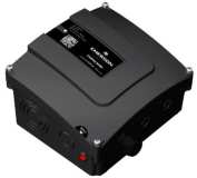

Figure 1: Terminal box Figure 2: Internal view of terminal box
1. Unscrew the 4 screws located in the corners of the compressor terminal box cover and lift off the terminal box cover.
2. Open the cover of the Copeland Compressor Electronics module to access the terminals.
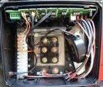
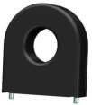
Figure 3: Copeland Compressor Electronics module cover open Figure 4: Current sensor
3. Supply 115 V or 230 V power (N and L1) to the module on extreme left terminals 1 and 2 (both polarities are possible).
4. Position the jumpers according to starting method and motor type. The jumper position is given on the compressor wiring diagram.
5. Connect the power supply to the terminal plate.
6. Caution! For part-winding, the power leads from the same phase should go through the current sensor in the same direction.
TI_Stream_NGCS_04_E_Rev04 1/2
7. Connect the Copeland Compressor Electronics module cables for the phase monitoring to terminals U/V/W (2 times 3 cables for each winding, grey GR, black BK and brown BN wires), and to the earth PE (pink PK wire).

IMPORTANT
For Stream CO2 small and medium compressor models (4MTL-05 to 4MTL-30 & 4MSL03 to 4MSL-15), the blue positions 1U, 2V, 3W, 7Z, 8X, 9Y in diagram below must be considered. The position of the terminals in all the other Stream compressor models corresponds to the black positions. The factory delivery is correct, DO NOT reverse the connections.
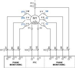
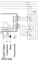
Figure 5: Wiring diagram Connections for phase monitoring Figure 6: Control circuit connection
8. Connect the control circuit phase (L) to terminal 19 (Figure 6).
9. Connect the crankcase heater to terminals 3 and 4, and to earth. The Copeland Compressor Electronics module controls the crankcase heater directly, so only a crankcase heater with the same power supply as the module (115 VAC or 230 VAC) can be selected.
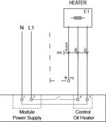
Figure 7: Wiring diagram Crankcase heater connections
NOTE: This document is for quick installation purposes. For detailed instructions, please refer to Technical Information TI_Stream_NGCS_01_E “Copeland™ Compressor Electronics for Copeland™ Stream Compressors”.
TI_Stream_NGCS_04_E_Rev04 2/2
EMERSON Copeland Compressor Electronics for Copeland Stream Compressors Installation Guide – EMERSON Copeland Compressor Electronics for Copeland Stream Compressors Installation Guide –
[xyz-ips snippet=”download-snippet”]