
EMERSON EC3-XEV02D Slave Driver for Digital Compressors User Manual
GENERAL WARNING
PLEASE READ BEFORE USING THIS MANUAL
- This manual is part of the product and should be kept near the instrument for easy and quick reference.
- The instrument shall not be used for purposes different from those described hereunder. It cannot be used as a safety device.
- Check the application limits before proceeding.
- Emerson reserves the right to change the composition of its products, even without notice, ensuring the same and unchanged functionality.
SAFETY PRECAUTIONS
- Check the supply voltage is correct before connecting the instrument.
- Do not expose to water or moisture: use the controller only within the operating limits avoiding sudden temperature changes with high atmospheric humidity to prevent formation of condensation
- Warning: disconnect all electrical connections before any kind of maintenance.
- Fit the probe where it is not accessible by the End User. The instrument must not be opened.
- In case of failure or faulty operation send the instrument back to the distributor or to Emerson with a detailed description of the fault.
- Consider the maximum current which can be applied to each relay (see Technical Data).
- Ensure that the wires for probes, loads and the power supply are separated and far enough from each other, without crossing or intertwining.
- In case of applications in industrial environments, the use of mains filters (our mod. FT1) in parallel with inductive loads could be useful.
GENERAL DESCRIPTION
The EC3-XEV02D is a slave module designed to be used with a master controller. It acts as a pure transducer controller, receiving a regulating input from a master controller and transforming it in the relative modulating signal for the digital unloader valve. The EC3-XEV02D module is equipped with a temperature probe input (which could be an NTC86K or NTC/PT1000 type). It has a digital output (relay) which is used for alarm or as compressor output, an open collector output which can be used as alarm output and a modulating output (TRIAC type) to drive the unloader digital valve. There are also two configurable digital inputs, the first one is free of voltage and the other ones is isolated in order to simplify connections (high voltage input). The display permits to see the value of temperature or the control input value or the output activation value in percentage. The local keyboard allows programming the instrument without any other devices. To complete instrument equipment, a RS485 serial port permits to connect the EC3-XEV02D to any modbus network and an HOT-KEY port to change configuration are present.
WIRING CONNECTIONS
Please use the following scheme to make the right wiring.
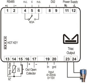
NOTE
- The DIGITAL valve must be connected directly to terminals 23 and 24
- The TRIAC output will work at the same power supply of the module
- The high voltage digital input (D.I.2, terminals 8-9) works at the same voltage of the Power Supply.
ALARM FUNCTIONS
HIGH TEMPERATURE ALARM CONTROL (TRIP)
DLT alarm is generated when DLT probe (P2) temperature is: T >= dLt

Until alarm delay time (dLd) is active the total compressor capacity will be limited to Cdd.
If alarm delay time (dLd) is disabled or elapsed:
- General alarm LED and digital output set as alarm (oAx = ALr) is activated
- If a digital output is set as compressor output (oA1 = CPr) this is also deactivated.
- If a digital output is set as demand output (oA1 = dmd) this is also deactivated.
- Solenoid valve control output deactivates.
- Buzzer activates (depending on the bEn parameter).
Alarm reset is automatic and happens when both of the following conditions occur:
- Temperature measured by probe will be T ≤ dLt – dth and
- Upon expiry of the stand-by timer for compressor head cooling (par. dCt).
In any case the regulation always re-starts after expiring both anti-short cycle timers 2on (minimum time between two consecutive compressor activations) and 2oF (minimum time between one compressor stop and next start-up).
Press any key to deactivate the buzzer at any time.
HIGH TEMPERATURE ALARM CONTROL (LOCKOUT)
DLT lockout alarm occurs after a dLn number of DLT alarms during the time interval (in hours) dLi. The logic behind this control is as follows:
- if dLn = 0, this control is deactivated (whatever the value of dLi);
- if dLn ≠ 0 and dLi = 0, block occurs after a number of DLT alarms equal to dLn is had.
- if dLn ≠ 0 and dLi ≠ 0, block occurs after a number of DLT alarms equal to dLn in time interval in dLi (expressed in hours).
When the above-described condition occurs:
- General alarm LED and digital output set as alarm (oAx = ALr) is activated.If a digital output is set as compressor output (oA1 = CPr) this is also deactivated.
- If a digital output is set as demand output (oA1 = dmd) this is also deactivated.
- Solenoid valve control output deactivates.
- Buzzer activates (depending on the bEn parameter).
Alarm reset is manual by means of controller on-off procedure or a special Modbus control.In any case the regulation always re-starts after expiring both anti-short cycle timers 2on (minimum time between two consecutive compressor activations) and 2oF (minimum time between one compressor stop and next start-up).
Press any key to deactivate the buzzer at any time.
LOW TEMPERATURE ALARM CONTROL (LOCKOUT)
If the temperature probe P2 measures a lower value than the one set in parameter ALL and if this condition persists for longer than the value set in parameter dLL:
- General alarm LED and digital output set as alarm (oAx = ALr) is activated.
- If a digital output is set as compressor output (oA1 = CPr) this is also deactivated.
- Solenoid valve control output deactivates.
- Buzzer activates (depending on the bEn parameter)
Alarm reset is manual by means of controller on-off procedure or by using a special MODBUS command.
In any case the regulation always re-starts after expiring both anti-short cycle timers 2on (minimum time between two consecutive compressor activations) and 2oF (minimum time between one compressor stop and next start-up).
Press any key to deactivate the buzzer at any time
MISSING REGULATION SIGNAL CONDITION (TRIP)
A missing regulation signal alarm is generated if the control signal drops below the value set in the parameter dSL (percentage value, if dSL = 0 this control is deactivated) and if this condition persists longer than dEr seconds.
If so:
- General alarm LED and digital output set as alarm (oAx = ALr) is activated.
- If a digital output is set as compressor output (oA1 = CPr) this is also deactivated.
- Solenoid valve control output deactivates.
- Buzzer activates (depending on the bEn parameter).
 Alarm reset is automatic and happens as soon as control exceeds value set in parameter dSL. If oA1 = CPr, the regulation always re-starts after expiring both anti-short cycle timers 2on (minimum time between two consecutive compressor activations) and 2oF (minimum time between one compressor stop and next start-up). Press any key to deactivate the buzzer at any time.
 Alarm reset is automatic and happens as soon as control exceeds value set in parameter dSL. If oA1 = CPr, the regulation always re-starts after expiring both anti-short cycle timers 2on (minimum time between two consecutive compressor activations) and 2oF (minimum time between one compressor stop and next start-up). Press any key to deactivate the buzzer at any time.
FRONT PANEL

| To display and to modify the set point. In programming mode it selects a parameter or it confirms a value | |
 |
Keep it pressed for 3 seconds to enter the information menu. In programming mode it slides the codes of the parameters or it increases their values |
 |
Keep it pressed for 3 seconds to enter the information menu. In programming mode it slides the codes of parameters or it decreases their values. |
 |
To enter the alarms archive menu. Keep it pressed for 3 seconds to switch OFF and ON the device (if A2F = oFF) |
KEY COMBINATIONS
|
To lock or to unlock the keyboard |
|
To enter programming mode |
|
To exit from various menu |
|
To erase the alarm database (when into alarm menu) |
EC3-XEV02D LEDS
On display there are some luminous dots. Their meaning is described in the following table:
| LED | MODE | Function |
| L | ON | |
| H | ON | High temperature alarm (DLT alarm) |
| In | BLINKING | TRIAC output is working |
| RS | BLINKING | Serial communication is working |
| kPA | ON | Units of measurement in dakPA |
| °C, °F, bar, PSI | ON | Units of measurement in °C, °F, bar or PSI |
| sec | ON | Units of measurement in seconds |
| (t) | ON | Alarm active |
USER INTERFACE
ACCESS THE VARIABLES MENU
Keeping the UP key pressed for 3 seconds when in normal operation mode (variables display) with U2F = viS, grants access to variables’ quick display menu. Press the SET key to switch from displaying the variable’s label to its value, and vice-versa. The variables displayed in sequence are: cycle time of digital modulating (tdG label) expressed in seconds, regulation input in percentage (irP label), regulation input expressed as analogical value (iAn label), P2 probe input (P2 label), valve regulation output in percentage (PEr label), the used machine configuration (CtY parameter), the parameter indicating any change on critical parameters (Mod). In addition to these, the firmware release date can be read by using par. FYr (year), FMn (month) and FdY (day).
Scroll the variables inside the menu by pressing the UP and DOWN keys. Whatever position you are in, press the SET+UP keys or waiting for the 60 seconds time-out to expire without pressing any key to exit the quick display menu.
NOTES
- Cycle time tdG is indicated in seconds with “sec” LED on
- Values display in percentage go from 0.0 % to 100.0 %
- The temperature is displayed with its units of measurement
- This procedure is possible when t1F, U2F or d2F = viS
PROGRAMMING CYCLE TIME tdG
Keep the SET button pressed for 3 seconds to gains access to the digital modulating menu time (tdG parameter). The display will show the tdG label once accessed. Press the SET key to switch to parameter’s value. Menu exit is for time-out (60 seconds without pressing any key) or by pressing the SET+UP keys again.
HOW TO: ENTERING “PR1” PARAMETER MENU
To access the “Pr1” level menu:
- Keep both SET+DOWN buttons pressed for 3 seconds.
- The instruments will show the first parameter present in the “Pr1” menu.
ACCESS TO “PR2” PARAMETER MENU
To access to “Pr2” menu:
- Enter the “Pr1” menu
- Select “Pr2” parameter and press SET.
- The “PAS” label will be shown, then “0—” with 0 blinkingInsert “321” password through UP and DOWN buttons, then press SET to confirm.
CHANGE A PARAMETERS VALUE
To change any parameter value, follow this procedure:
- Enter the Programming mode by keeping the SET+DOWN buttons pressed for 3 seconds.
- Select the required parameter.
- Press the SET button to display the value.
- Use UP or DOWN to change the value.
- Press SET to store the new value and move to the following parameter
To exit: press SET+UP or wait for 30 seconds without pressing any button.NOTE: the set value is stored even when the procedure is excited by waiting the time-out to expire.
PARAMETER LIST
REGULATION
| oA1 | Digital output 1 configuration: nu = not used; ALr = alarm output; CPr = compressor output; dmd = do not use it. |
| oA2 | Digital output 2 configuration (open collector output): nu = not used; ALr = alarm. |
| oP1 | Digital output 1 polarity: oP = open; CL = closed. |
| oP2 | Digital output 2 polarity: oP = open; CL = closed. |
| tbA | Alarm output deactivation (only if oAx = ALr): n = not permitted; Y = permitted. |
| bEn | Buzzer (software) management: on = buzzer active; oFF = buzzer disabled. |
| P2C | Temperature probe configuration (it depends on the hardware): nu = not used;
Pt1 = PT1000; ntC = NTC10 k probe; n86 = NTC86 k probe. |
| o2 | Probe P2 calibration: -12 – 12°C; -21 – 21°F |
| PA4 | Analogue input at 4 mA or 0 V: (0 – 100 %) set the percentage value relative to the minimum analogue input. |
| P20 | Analogue input at 20 mA or 10 V: (0 – 100 %) set the percentage value relative to the maximum analogue input. |
| Sut | Start-up time: (0.0 – 25.5 s) valve activation time before starting the regulation. |
| tdG | Modulation time interval: 6 – 40 s |
| 2on | Minimum delay between two DG compressor start-ups: 0 – 255 min |
| 2oF | Delay between DG compressor switch-off and start-up: 0 – 999 s |
| odo | Power on regulation delay: (0 – 999 s) the regulation starts after this delay |
| dSL | Lower limit for control signal (in percentage): 0 – 100 % |
| Si0 | Minimum analogue input value (in percentage): 0 – 100 % |
| Si1 | Maximum analogue input value (in percentage): 0 – 100 % |
| PMi | Minimum load (in percentage): 0 – 100 % |
| PMA | Maximum load (in percentage): 0 – 100 % |
DISPLAY
| Lod | Default displayed variable: Per = TRIAC output activation in percentage;
Ain = analogue input value in percentage; P2 = temperature measured form probe P2. |
| CF | Units of measurement for temperature: °C = Celsius; °F = Fahrenheit. |
| rES | Temperature resolution (valid only if CF = °C): in=integer; dE = decimal. |
DIGITAL INPUTS
| i1F | Digital input 1 configuration (voltage free contact): nP = disabled;
EAL = external alarm; bAL = block alarm; onF = regulation enabled. |
| i2F | Digital input 2 configuration (powered input): nP = disabled;
EAL = external alarm; bAL = block alarm; onF = regulation enabled. |
| i1P | Digital input 1 polarity: oP =open; CL = closed. |
| i2P | Digital input 2 polarity: oP = open; CL = closed. |
ALARMS
| ALL | Low temperature alarm: (-30 – 200 °C; -22 – 392 °F) this alarm blocks the regulation. A manual reset required. |
| dLL | Low temperature alarm activation delay: 0 – 999 s |
| dLt | Discharge line temperature: (-30 – 200 °C; -22 – 392 °F) value used for compressor block and alarm output activation. |
| dth | Differential: (0 – 99.9 °C; 0 – 999 °F) used to restart the compressor after any DLT alarm. |
| dLd | DLT alarm activation delay: 0 – 999 s |
| dCt | Cooling time for DG compressor after DLT alarm: 0 – 255 min |
| dLn | Number of DLT alarms in dLi hours before blocking compressor: 0 – 15, 0 = function disabled. |
| dLi | Time interval (in hours) in which to check dLn number of DLT alarms:
0 – 24 hours; 0=function disabled. |
| CEd | Maximum compressor capacity (in percentage) in case of probe error: 0 – 100 % |
| Cdd | Maximum compressor capacity (in percentage) in case of DLT alarm and for time dLd: 0 – 100 % |
| CEi | Maximum compressor capacity (in percentage) in case of regulation input error:
0 – 100 % |
| dEr | Alarm delay in case of regulation input/probes reading error: 0 – 999 s |
OTHER
| A2F | ALARM key timed function configuration (push button timed, 3 s): nu = not used; onF = ON-OFF function. |
| Adr | Serial address: 1 – 247 |
| bAU | Baudrate for serial communication: 9.6 = 9600 baud; 19.2 = 19200 buad. |
| dP1 | Analogue output value (read only) |
| dP2 | Probe P2 value (read only) |
| d1S | Digital input status display (isolated contact) (read only) |
| d2S | Digital input status display (not isolated contact) (read only) |
| rEL | Release Firmware (read only) |
| Ptb | Parameters table code (read only) |
| Pr2 | Protected parameters menu access |
DIGITAL INPUTS
The device is provided with two digital inputs. One is free of voltage and the other is at high voltage and both can be configured as cooling call. In this way the cooling signal can come from instruments with direct load outputs or via instruments with output without voltage.
ELECTRICAL CONNECTIONS
The instrument is provided with pluggable screw terminal block to connect cables with a cross section up to 2.5 mm2 Heat-resistant cables have to be used. Before connecting cables make sure the power supply complies with the instrument’s requirements. Separate the probe cables from the power supply cables, from the outputs and the power connections. Do not exceed the maximum current allowed on each relay, in case of heavier loads use a suitable external relay.
RS485 SERIAL LINE
All models can be connected to a MODBUS network by using the 2-wire RS485 port. The XWEB related library and the MODBUS protocol can be issued on customer request from Emerson.
USE THE HOT-KEY
PROGRAM A HOT-KEY FROM THE INSTRUMENT (UPLOAD)
- Program one controller with the front keypad.
- When the controller is ON, insert the HOT-KEY and push UP button; the “uPL” message appears followed a by flashing “End”.
- Push SET button and the “End” will stop flashing.
- Turn OFF the instrument, remove the HOT-KEY and then turn it ON again.
NOTE: The “Err” message is displayed in case of any failed programming operation. In this case, push again UP button if you want to restart the upload again or remove the HOT-KEY to abort the operation.
PROGRAM AN INSTRUMENT USING A HOT KEY (DOWNLOAD)
- Turn OFF the instrument.
- Insert a pre-programmed HOT-KEY into the 5-PIN connector and then turn the Controller ON.
- Automatically the parameter list present into the HOT-KEY will be downloaded into the Controller memory. The “doL” message will blink during this operation, followed a by a flashing “End” label.
- After 10 seconds the instrument will restart working with the new parameters.
- Remove the HOT-KEY.
NOTE: The “Err” message is displayed in case of any failed programming operation. In this case, push again UP button if you want to restart the upload again or remove the HOT-KEY to abort the operation.
Press the ALARM button to access the alarms database menu if. This menu contains a LIFO format log of the last 10 registered alarms. The menu structure is as follows:
- the alarm number in AL0…AL9 format (0 is the oldest alarm, 9 is the last received alarm) is displayed once accessed.
- it is possible to scroll the registered alarms by using the UP and DOWN buttons.
- it is possible to display the following alarm information (in sequence) by using the SET button: the alarm code (3-digit label according to that described) and alarm duration in h.mm (1 min resolution, max stored value is 19 h 59 min).
ALARMS ARCHIVE ERASING:
All saved alarms can be deleted by keeping the ALARM+SET key pressed for 5 seconds when into ALARM MENU. The display will show the “rSt” l
NOTE: All saved alarms can be also deleted via special MODBUS command.
DISPLAY MESSAGES
| Mess. | Cause | Outputs |
| A02 | Digital input configured as EAL function is active | Unchanged |
| A03 | Missing regulating signal (analogue input drops below dSL value) | Unchanged |
| E01 | DLT alarm active | Output disabled, alarm output activated |
| E02 | A dLn number of DLT alarms in time interval (in hours) dLi was detected. | Output disabled, alarm output activated |
| E03 | Digital input configured as bAL function is active | Output disabled, alarm output activated |
| E05 | Missing regulating signal (analogue input drops below dSL value more than dEr time) | Output disabled, alarm output activated |
| E07 | Low temperature alarm active | Output disabled, alarm output activated |
| P1 | Analogue input error | Output disabled, alarm output activated |
| P2 | Temperature transducer in error | Output disabled, alarm output activated |
ALARM RECOVERY
Probe alarms “P1” and “P2” start dEr seconds after the fault in the read value; they automatically stop few seconds after the probe restarts normal operation. Check connections before replacing the probe.Alarms E01, E03 and E05 automatically stop as soon as their root causes disappear.Alarm E02 and E07 require a manual re-start by switching OFF and ON the device or by sending a MODBUS command.
TECHNICAL DATA
- Housing: self-extinguishing ABS
- Case: 4 DIN modules 70 x 135 mm with male and female connectors; depth 60 mm
- Mounting: DIN RAIL mounted in an omega (3) DIN rail
- Protection: IP20
- Connections: screw terminal block ≤ 2.5 mm2 wiring
- Power supply: 24VAC/DC ±10 %; 110 VAC ±10 % or 230 VAC ±10 %
- Power absorption: depending on connected valve 20 VA max.
- Display: 3.5 digits with icons, red LEDs, height 14.2 mm
- Temperature input: 1 temperature probe
- PT1000 probe: -55 – 200 °C (-67 – 392 °F)
- NTC10k probe: -40 – 110 °C (-40 – 230 °F)
- NTC86k probe: -40 – 180 °C (-40 – 356 °F)
Analogue control input:
| 0 – 10 VDC | |
| 4 – 20 mA | |
| Digital inputs: | 1 free of voltage
1 isolated (voltage depending on the power supply) |
| Digital outputs: | 1 relay output, 8(3) A, 250 VAC
1 open collector output, max current 40 mA |
| TRIAC output: | max 30 W |
| Data storage: | on the non-volatile memory (EEPROM |
| Kind of action: | 1 B |
| Pollution degree: | norma |
| Software Class: | A |
| Operating temperature: | 0 – 55 °C (32 – 131 °F) |
| Storage temperature: | -25 – 60 °C (-13 – 140 °F) |
| Relative humidity: | 20 – 85 % (no condensing) |
| Resolution: | 0.1 °C or 1 °F |
| Precision a 25°C (77°F): | ±0.7 °C ±1digit |
STANDARD VALUES
| Label | Description | Range | Default | Level |
| oA1 | Digital output 1 configuration | nu; ALr; CPR; dmd | CPr | Pr1 |
| oA2 | Digital output 2 (o.c.) configuration | nu, ALr | nu | Pr2 |
| oP1 | Digital output 1 polarity | oP; CL | oP | Pr1 |
| oP2 | Digital output 2 (o.c.) polarity | oP; CL | oP | Pr2 |
| tbA | Alarm output deactivation | no; Yes | no | Pr2 |
| bEn | Buzzer (software) management | on; oFF | on | Pr2 |
| P2C | Temperature probe configuration (it depends on the hardware) | nu; Pt1; ntC; n86 | (*) | Pr1 |
| o2 | Probe P2 calibration | -12 – 12 °C; -21 – 21 °F | 0.0 | Pr1 |
| PA4 | Analogue input at 4mA or 0V | 0 – 100 % | 0.0 | Pr2 |
| P20 | Analogue input at 20mA or 10V | 0 – 100 % | 100 | Pr2 |
| Lod | Default displayed variable | PEr; Ain; P2 | PEr | Pr1 |
| CF | Units of measurement for temperature | °C; °F | °C | Pr1 |
| rES | Temperature resolution (valid only if CF=°C) | in; dE | dE | Pr1 |
| i1F | Digital input 1 configuration (voltage free contact) | nP; EAL; bAL; onF | EAL | Pr1 |
| i2F | Digital input 2 configuration (high voltage input) | nP; EAL; bAL; onF | onF | Pr1 |
| i1P | Digital input 1 polarity | oP; CL | CL | Pr1 |
| i2P | Digital input 2 polarity | oP; CL | CL | Pr1 |
| Sut | Start-up time: valve activation time before starting the regulation | 0.0 – 25.5 s | 3.0 | Pr1 |
| tdG | Modulation time interval | 6 – 40 s | 20 | Pr1 |
| ALL | Low temperature alarm | -30 – 200 °C;
-22 – 392 °F |
-30 | Pr2 |
| dLL | Low temperature alarm activation delay | 0 – 999 s- | 180 | Pr2 |
| dLt | Discharge line temperature | -30 – 200 °C;
-22 – 392 °F |
145 | Pr1 |
| dth | Differential | 0 – 99.9 °C;
0 – 999 °F |
10 | Pr1 |
| dLd | DLT alarm activation delay | 0 – 999 s | 60 | Pr1 |
| dCt | Cooling time for DG compressor after DLT alarm | 0 – 255 min | 10 | Pr1 |
| dLn | Number of DLT alarms in dLi hours before blocking compressor | 0 – 15, 0 = function disabled | 0 | Pr2 |
| dLi | Time interval (in hours) in which to check dLn number of DLT alarms | 0 – 24 hours; 0 = function disabled | 0 | Pr2 |
| CEd | Maximum compressor capacity (in percentage) in case of probe error | 0 – 100 % | 100 | Pr2 |
|
Cdd |
Maximum compressor capacity (in percentage) in case of DLT alarm and for time dLd | 0 – 100 % | 100 | Pr2 |
|
CEi |
Maximum compressor capacity (in percentage) in case of regulation input error | 0 – 100 % | 100 | Pr2 |
| dEr | Alarm delay in case of regulation input/probes reading error | 0 – 999 s | 30 | Pr2 |
| 2on | Minimum delay between two DG compressor start-ups | 0 – 255 min | 5 | Pr1 |
| 2oF | Delay between DG compressor switch-off and start-up | 0 – 999 s | 120 | Pr1 |
| odo | Power on regulation delay | 0 – 999 s | 5 | Pr1 |
| dSL | Lower limit for control signal (in percentage). 0=function disabled. | 0 – 100 % | 0 | Pr2 |
| Si0 | Minimum input value in percentage | 0 – 100 % | 0 | Pr2 |
| Si1 | Maximum input value in percentage | 0 – 100 % | 100 | Pr2 |
| PMi | Minimum load in percentage | 0 – 100 % | 0 | Pr2 |
| PMA | Maximum load in percentage | 0 – 100 % | 100 | Pr2 |
|
A2F |
ALARM key timed function configuration (push button timed, 3 sec) | nu; onF | nu | Pr2 |
| Adr | Serial address | 1 – 247 | 1 | Pr2 |
| bAU | Baudrate for serial communication | 9.6; 19.2 | 9.6 | Pr2 |
| dP1 | Analogue control signal (read only) | – | Pr1 | |
| dP2 | Probe P2 display (read only) | – | Pr1 | |
| d1S | Digital input status display (isolated input) | – | Pr1 | |
| d2S | Digital input status display (high voltage input) | – | Pr1 | |
| rEL | Release Firmware (read only) | – | Pr1 | |
| Ptb | Parameters table code (read only) | – | Pr1 | |
| Pr2 | Protected parameters menu access | – | Pr1 |
Emerson Climate Technologies GmbH Am Borsigturm 31 I 13507 Berlin I Germany.www.climate.emerson.com/en-gb
References
[xyz-ips snippet=”download-snippet”]