EMERSON IPS200D iPro Small High Pressure Controller User Guide

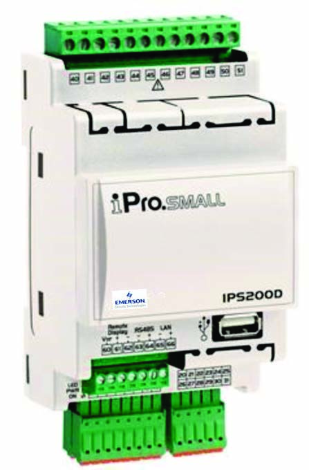
The High Pressure CO2 controller (P/N 818-9010) application is a standalone controller that operates the High Pressure Valve (HPV) and the Bypass Gas Valve (BGV) in a Booster Transcritical CO2 system. The controller has a heat reclaim feature, safety parameter operation for the flash gas receiver tank and calibration feature for the HPV and BGV. For E2 setup information, click here or scan the QR code:
CAUTION! GND is Common, not earth ground. Do not earth ground this device.

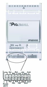
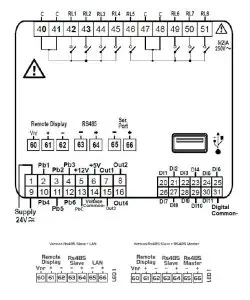
The High Pressure CO2 Controller I/O Points
The board has 6 analog inputs and 11 digital inputs, with default configurations pre-loaded for quick connection to for gas cooler pressure outlet, gas cooler temperature, flash gas receiver pressure and enable digital input. Its 8 relay outputs, rated 2.0 amps max, are used for activating and deactivating alarms. Its 4 analog outputs may be used for a 0-10 volt signal for external valve driver for either the HPV or BGV.
Independent System Control
The High Pressure CO2 controller can control the HPV and BGV in a refrigeration Booster Transcritical CO2 System. However, the High Pressure CO2 controller is designed to interface with an E2. Networking the High Pressure CO2 controller to a central controller also allows you to view status on E2 and UltraSite32 Site Manager status screens, report alarms, and log point values. The High Pressure CO2 controller configuration can be programmed through the E2 front panel.
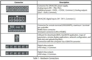
Hardware Connections
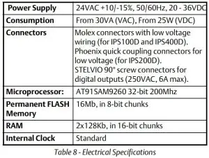
Technical Specifications
Analog Inputs

CAUTION! Any inputs that are powered with a voltage that differs from that supplied by the device (+12V or +5V) must be powered separately with another transformer (do not use the same secondary of the controller’s power) in order to prevent the inputs from malfunctioning or being damaged.
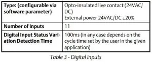
Digital Inputs
CAUTION! Use another transformer (do not use the same secondary of the controller’s power) in order to prevent the inputs from malfunctioning or being damaged.
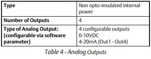
Analog Outputs
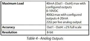
CAUTION! The electrical devices controlled by these analog outputs must be powered separately with another transformer (do not use the same secondary of the controller’s power) in order to prevent the outputs from malfunctioning or being damaged.
Digital Outputs
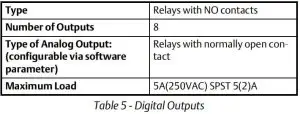
CAUTION! Verify the capacity of the output used. There is double insulation between the digital outputs and the low voltage of the rest of the circuit. Do not use different voltages for the various groups of relays or within each group.
Analog Inputs
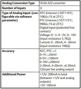
Table 6 – Analog Inputs
CAUTION! Any inputs that are powered with a voltage that differs from that supplied by the device (+12V or +5V) must be powered separately with another transformer (do not use the same secondary of the controller’s power) in order to prevent the inputs from malfunctioning or being damaged.
Digital Inputs
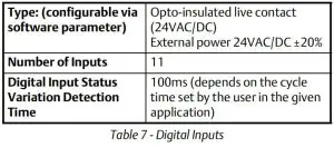
CAUTION! Use another transformer (do not use the same secondary of the controller’s power) in order to prevent the inputs from malfunctioning or being damaged.
Electrical Specifications
Choosing Transformer SizesThe transformer used to power the High Pressure CO2 controller should have a minimum rating of 30VA. The High Pressure CO2 controller should not share a transformer with any other devices.
![]()
Neither side of the secondary should be connected to ground. Also, do not connect the center tap (if provided on the transformer) to ground. The entire secondary of the transformer should be isolated from any ground.
Wire Types
For powering I/O boards, use only the listed wire type below. Two-conductor non-shielded cables are the recommended wire for connecting the transformer to the High Pressure CO2 controller. Shielded cable should not be used for power wiring. The center tap should be left disconnected if present on the transformer.
![]()
Wiring
Non-Center Tapped Transformer Wiring
Wiring Connections
Note: To ensure control in case of a power failure, it is recommended that a UPS be used on the High Pressure CO2 controller.
Modbus
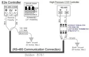
Modbus Network Connections
For more information, click here or scan the QR code.
Document Part # 026-4974 Rev 0©2020 Emerson Retail Solutions, Inc. This document may be photocopied for personal use.Visit our website at http://www.climate.emerson.com for the latest technical documentation and updates.

This document may be photocopied for personal use.Visit our website at http://www.emerson.climate.com for the latest technical documentation and updates.Join Emerson Technical Support on Facebook http://on.fb.me/WUQRntFor Technical Support call 770-425-2724 or email [email protected]The contents of this publication are presented for informational purposes only and they are not to be construed as warranties or guarantees, express or implied, regarding the products or services described herein or their use or applicability. Emerson Climate Technologies Retail Solutions, Inc. and/or its affiliates (collectively “Emerson”), reserves the right to modify the designs or specifications of such products at any time without notice. Emerson does not assume responsibility for the selection, use or maintenance of any product. Responsibility for proper selection, use and maintenance of any product remains solely with the purchaser and end-user.Emerson is a trademark of Emerson Electric Co. ©2020 Emerson Climate Technologies Retail Solutions, Inc. All rights reserved.
 report this ad
References
[xyz-ips snippet=”download-snippet”]