Lumity™ Site Supervisor ControllerQuick Setup Guide
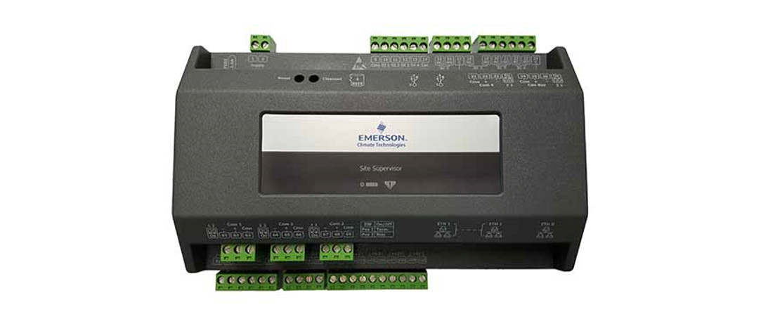
The Lumity Site Supervisor is a system that combines energy management with the ability to monitor various facility systems and provide alerts when there are issues that need attention. This system provides HVAC control, Refrigeration System Monitoring and Control, as well as Lighting Control. In addition, the Site Supervisor can monitor and report energy consumption and take action to reduce the energy demand during peak periods. This can have a direct impact on utility bills by reducing total energy costs. The Site Supervisor ensures that the HVAC and lighting systems are on and off at the appropriate times. This ability to monitor store conditions can potentially minimize energy consumption.
For a copy of the latest Supervisory Control user manual (P/N 026-1803), visit the Lumity Site Supervisor page on the Emerson website: https://climate.emerson.com/en-us/products/controls-monitoring-systems/facilitycontrols-electronics/facility-and-system-controls/lumity-supervisory-controlsplatform to download or contact Emerson Electronics and Solutions Technical Support at 833-409-7505.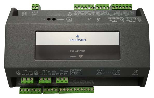 Figure 1 – Site Supervisor
Ethernet Connection
- ETH1 is designed to be used for directly connecting to a laptop, PC, or optional touchscreen with a CAT5 network cable.
- The default IP for ETH1 is 192.168.1.250.
- The optional Site Supervisor Display touchscreen default IP is 192.168.1.200 and will connect automatically to the Site Supervisor when plugged into ETH1. It is recommended that you do not change these defaults.
 Figure 2 – Site Supervisor ETH 1 Ports
 - ETH0 should be reserved for the secure network connections: store or corporate networks. Ask your network administrator for the correct network IP address for ETH0.
- ETH0 and ETH1 are physically separated for added security. Directly connecting to ETH1 will not access the secure network connection on ETH0.
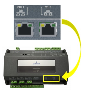 Figure 2 – Site Supervisor ETH 1 Ports
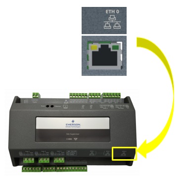
Figure 3 – Site Supervisor ETH 0 Port
Direct Connect Instructions – Connect your laptop to Site Supervisor’s Ethernet port ETH1:
- Under the Control Panel – Network and Sharing Center, select Change adapter settings.
- Select the Local Area Connection port being used.
- Select Properties.Figure 4 – Change Adapter Settings
- Highlight the section Internet Protocol Version 4 (TCP/IPv4) and click Properties:Figure 5 – Highlight Internet Protocol Version 4 (TCP/IPv4)
- Click Use the following IP address: and enter the IP address 192.168.1.251 and the Subnet mask 255.255.255.0 of the PC being used on the Local Area Network or direct connection and click OK:Figure 6 – IP Address and Subnet Mask
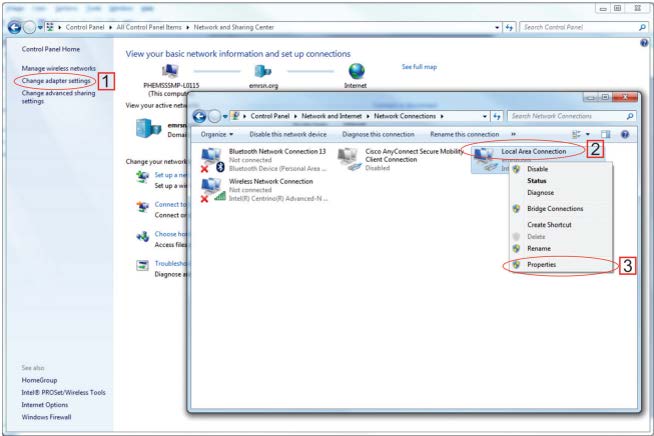 Figure 4 – Change Adapter Settings
 Figure 5 – Highlight Internet Protocol Version 4 (TCP/IPv4)
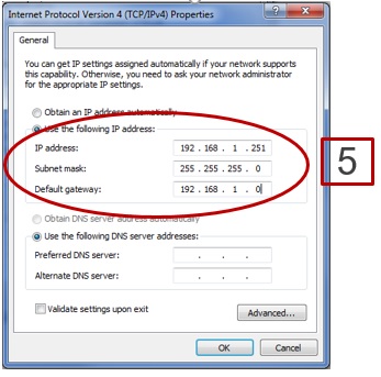 Figure 6 – IP Address and Subnet Mask
Logging Into the Site Supervisor
- Launch a preferred Web browser: IE 9 and above, Firefox 13 and above, Chrome (all versions), and Safari (all versions) are the supported browsers.
- Enter the IP Address of the device.
- Enter your Username/Password (default user/pass) and click Login. Then update your password to the minimum complexity requirements and click Save.Note that when directly connecting your laptop or PC to ETH1, enter the default IP into the browser address bar: ETH1 Default IP Address is 192.168.1.250.Figure 7 – Login Screen at Controller Startup and Update Password

 Figure 7 – Login Screen at Controller Startup and Update Password
How to Change the IP Address
Method 1: Direct Connect
- Select the Main Menu icon > Configure System > General System Properties > Network Settings:Figure 8 – Enter IP Address in the ETH 0 IP Address Field
- On the INTERNET (TCP/IP) section on the screen, enter the IP Address in the ETH 0 IP Address field.
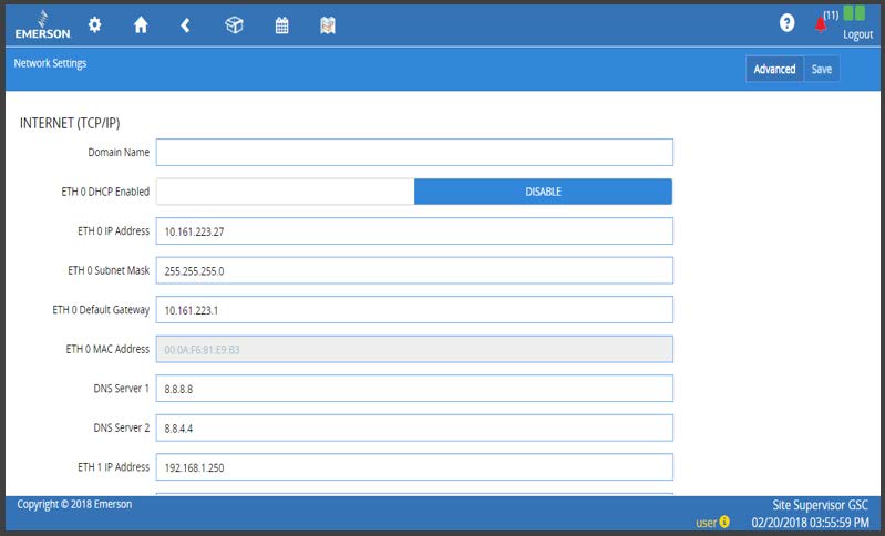 Figure 8 – Enter IP Address in the ETH 0 IP Address Field
Method 2: USB Port
- Create a “network.txt” with your desired settings (Figure 7):Figure 9 – Network.txt Notepad
- Save to the root folder of a thumb drive. Insert the thumb drive into the USB port of the Site Supervisor.
- Power cycle the Site Supervisor and the new IP Address will be saved.
 Figure 9 – Network.txt Notepad
Setup Wizard Note that if setpoints have been pre-loaded in the unit, the Setup Wizard will not auto-start after logging in.If your unit has been received directly from the Emerson factory, the Setup Wizard will open and take you through the following setup screens:
Localization Screen
 Figure 10 – Localization Screen
Set the Site Supervisor’s localization data such as language, date and time formats, and engineering units from the Localization screen.
Language: The default for the language selection is American English (United States). The system stores a setting for the preferred system language (internal language code). The default language is used when no user is currently logged into the Site Supervisor or when the currently active preferred language does not have a translation for a given label, prompt, or display text.
Date: The Date format can be set to either Day, Month, and full Year (D-M-YR) or Month-Day and full Year (M-D-YR) format. The day, month, and year values are separated by either a forward slash or a dash line depending on user selection. The Date Format can be changed based on user preference and saved to user profiles. On initial Site Supervisor startup, the Date format defaults to the format of the language selected. For example, en-US will default to D-M-YR and all others will default to M-D-YR.
Time: The Time format can be set to either a 12-hour (12-hr) format or 24-hour (24-hr) format. The hour, minute, and second values are separated by either a colon or a period depending on user selection. The Time format can be changed based on user preference and saved to user profiles. On initial Site Supervisor startup, the Time format defaults to the format of the language selected. Date and Time delimiters default to forward slashes and colons.
Engineering Units: The default engineering units are based on the assigned units for the chosen preferred language. Users can choose or change their preferred set of engineering units and save them to their user profiles. The default engineering units are based on the International System of Units (SI System) format.Set the system language type in the Language drop-down menu. Click the right arrow > to save and proceed to the System Values screen.
System Values Screen
From the System Values screen, name the unit by entering it in the Site Name field. The Confirmation window will slide open. Click OK. Then click the right arrow > to proceed to the Network Settings Screen.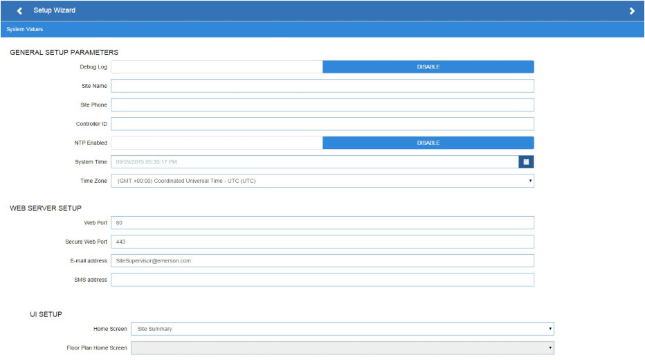
Figure 11 – System Values Screen
Network Settings ScreenConfigure the settings on the Internet TCP/IP screen such as host name, text, and email settings. If you have Internet access, enter the IP Subnet Mask and Default Gateway settings (see your IT Administrator). If connecting directly to a laptop, use the Default IP and leave the DHCP set to Disable. For text messaging, enable the SMS setting and use the SMTP address (see your IT Administrator).Click the arrow > to save and finish the Setup Wizard.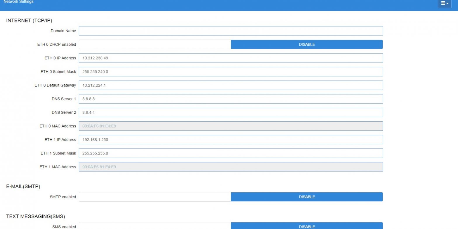
Figure 12 – Network Settings
For every Site Supervisor screen, the Main Menu, Home, Back Arrow, Control Inventory, and Schedules/Events icons appear at the first row of top of the screen. A screen title also appears at the top left of the screen.
Basic Screen Parts and Elements:
- Main Display – this is the main section of the screen, which contains and displays the content of the chosen selection such as reports, device information, configuration settings, and more.
- Menus and Submenus – these can be viewed on the Main Menu Panel. The Menus and Sub-menus are grouped into different categories. Each menu selection can have several sub-menus. When you click on a lowest sub-menu level, the screen of the chosen selection is displayed.Note: When some screen information and contents are clicked, more or related information can be displayed or additional screens accessed. For more information about icon descriptions and buttons, refer to the latest Supervisory Control manual P/N 026-1803.
LEDs
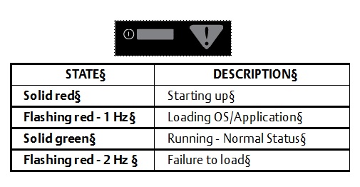 Figure 13 – LED Information
Termination Jumper Settings
 Figure 14 – Termination Jumper Settings
UL Ratings
|
Type |
Ratings |
Terminal |
| Relay 1 (N.O. & N.C.) | 5A, 125/240 VAC, General Purpose, 100K cycles;4FLA/4LRA, 250VAC, Motor Load, 100K cycles; | J5-2, J5-3, J5-4 (Base Board) |
| Relay 2 (N.O. & N.C.) | 5A, 125/240 VAC, General Purpose, 100K cycles;
4FLA/4LRA, 250VAC, Motor Load, 100K cycles; |
J5-1, J5-2, J6-6 (Base Board) |
| Relay 3 (N.O. & N.C.) | 5A, 125/240 VAC, General Purpose, 100K cycles;
4FLA/4LRA, 250VAC, Motor Load, 100K cycles; |
J6-1, J6-4, J6-5 (Base Board) |
| Relay 4 (N.O. & N.C.) | 5A, 125/240 VAC, General Purpose, 100K cycles;
4FLA/4LRA, 250VAC, Motor Load, 100K cycles; |
J6-1, J6-2, J6-3 (Base Board) |
Table 1 – UL Ratings
Housing Dimensions and Mounting

Figure 15 – Mounting Dimensions
The Site Supervisor can be mounted to standard 35mm DIN Rail. Snap the orange tabs on the back of the unit to the down position to fasten. If not using the DIN-Rail mounting option, fasten to the mounting surface using the openings in the mounting tabs. Pull the four orange mounting tabs out until they lock, which will expose the mounting holes.
Technical Specifications
| Operating Temperature | -40°F to 149°F (-40°C to 65°C) |
| Relative Humidity | 20-85% RH non-condensing |
| Enclosure Rating | UL 94 V-0 |
| Dimensions | 103.7 x 34.7mm |
| 24 VAC | 20VA required 24VAC/20VA |
| 1 Can Bus | Expansion Module Connections |
| 4 RS485 ports | MODBUS Com Ports 1, 2, 3, and 4 |
| 3 Ethernet ports | Ports 1, 1, 0 |
| 2 USB ports | 1, 2 |
| MicroSD | 1 |
| Analog Inputs | 8 |
| Digital Inputs | 4 |
| Relay Outputs | 4 |
Table 2 – Technical Specifications
Wiring Diagram
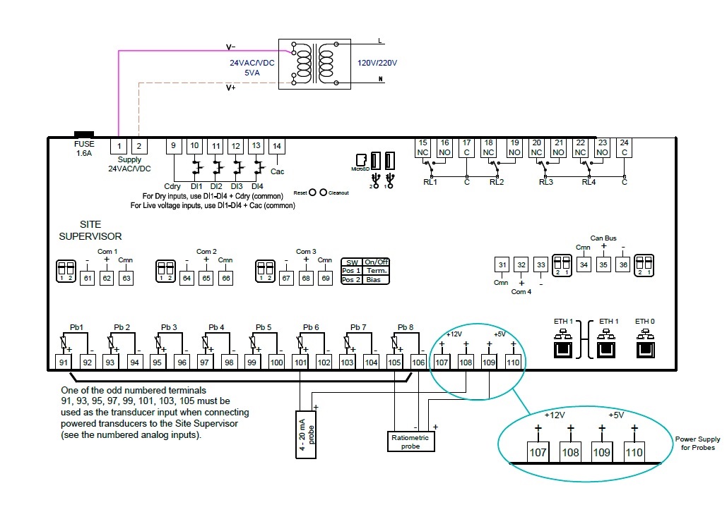 Figure 16 – Site Supervisor Wiring Diagram
Site Supervisor RS485 Wiring Guide ExamplesFor more wiring information, refer to the latest Supervisory Control user manual (P/N 026-1803).
- The Site Supervisor IONet connections must be wired reverse polarity.
- For the Site Supervisor Serial IONet connections, connect the white wire to the negative terminal and the black wire to the positive terminal.
- For 8RO and MultiFlex RS485 IONet connections, connect the white wire to the positive terminal and the black wire to the negative terminal.
- Connect the shield wire to earth/chassis at the Site Supervisor end of the IONet network segment. DO NOT connect the shield wire to any connector on the Site Supervisor.
- For daisy-chain configurations, terminate devices at the beginning and the end of the network segment. All other devices in the network segment are not terminated (termination jumpers in the not-terminated position).Site Supervisor and MultiFlex

Figure 17 – Site Supervisor, MultiFlex, and 8RO Wiring Layout
Notes:
- Transformers for 8R0 and Muftiflex 16A1 must be center-tapped, 24VAC. 15VA minimum per board.
- Transformer for MultiFlex ESR must be center-tapped 24VAC,80VA minimum per board.
- All other MuftiFlex board can be non-center-tapped or center-tapped 24VAC. 15VA minimum per board.
- MuItiFlex RS485 IONet is reverse polarity of Site Supervisor.
- The 318-4000 100-ohm resistor at Site Supervisor is optional but may be required in high-noise environments.
- The Site Supervisor and XR75CX shares the same MODBUS network polarity. Do not reverse polarity.
- Connect the shield wire to earth/chassis at the Site Supervisor end of the MODBUS network segment. Do not connect the shield wire to any connector on the Site Supervisor or XR75CX.
- For daisy-chain configurations, terminate devices at the beginning and the end of the network segment. Set the dip switch position 1 and 2 to the ON position on the Site Supervisor. For XR75CX end of network, terminate with a 150-ohm resistor or 535-2711 termination block. All other devices in the network segment are not terminated.Site Supervisor and XR75 (120V models)
Figure 18 – Site Supervisor and XR75CX Wiring Layout
NOTES:
- Ground shields at ends of MODBUS segment.
- Terminate MODBUS Network at the beginning and end of the network segment.
- Set Bias switch position to ON at Site Supervisor.
- Consult factory for configurations with mixed models.
- Maximum 50 XR7SCX devices, electrical loading only. Software limitations may apply.
Document Part # 026-4144 Rev 13
This document may be photocopied for personal use.Visit our website at http://www.climate.emerson.com for the latest technical documentation and updates.Join Emerson Technical Support on Facebook. http://on.fb.me/WUQRntFor Technical Support call 833-409-7505 or email [email protected]
The contents of this publication are presented for informational purposes only and they are not to be construed as warranties or guarantees, express or implied, regarding the products or services described herein or their use or applicability. Emerson Climate Technologies Retail Solutions, Inc. and/or its affiliates (collectively “Emerson”), reserves the right to modify the designs or specifications of such products at any time without notice. Emerson does not assume responsibility for the selection, use, or maintenance of any product. Responsibility for proper selection, use, and maintenance of any product remains solely with the purchaser and end-user.

References
Log into Facebook | Facebook
Climate Technologies Worldwide | Emerson US
HVACR Technology and Infrastructure Solutions | Emerson US
Lumity Supervisory Control Platform | Emerson US
Climate Technologies Worldwide | Emerson US
Climate Technologies Worldwide | Emerson US
Lumity Supervisory Control Platform | Emerson US
Log into Facebook | Facebook
[xyz-ips snippet=”download-snippet”]