![]() Refrigerant Gas Detector (MRLDS-450)for Machinery Rooms, Cold Rooms and FreezersQuick Start Guide
Refrigerant Gas Detector (MRLDS-450)for Machinery Rooms, Cold Rooms and FreezersQuick Start Guide
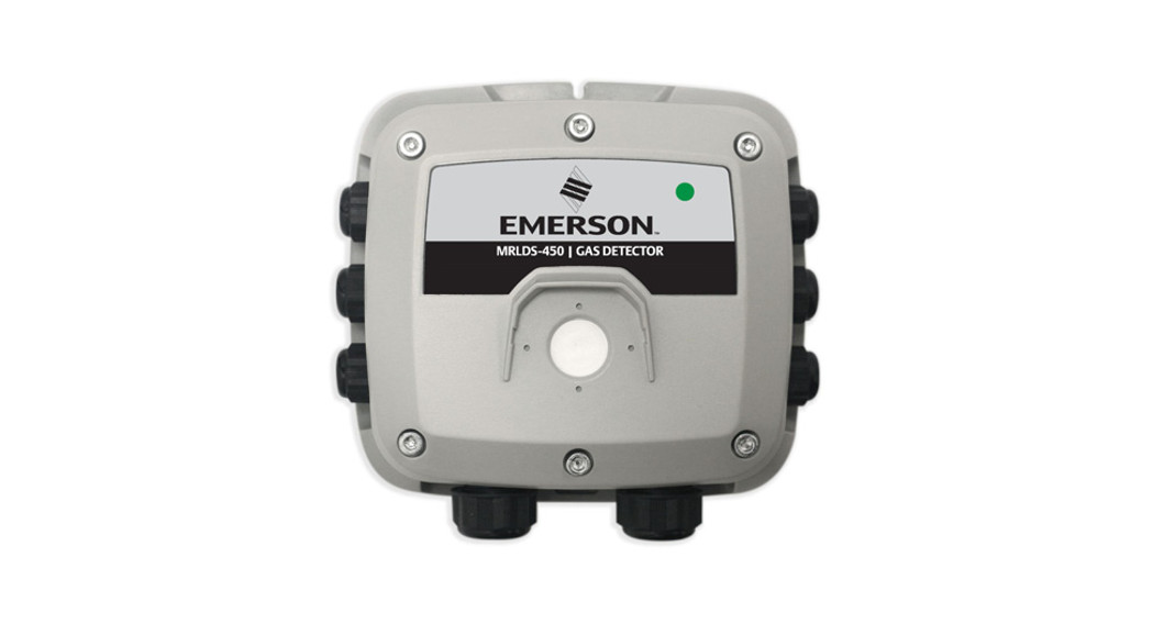
The MRLDS-450 refrigerant gas detector is designed for use in refrigeration applications and may be used as a stand-alone device, or connected to a facility’s building management system (BMS). It enables compliance with refrigerant safety codes (ASHRAE 15 and EN378) and features audible and visual alarms to alert personnel in the event of a refrigerant leak.
Safety Instructions
 DANGER: The MRLDS-450 is NOT certified or approved for operation in oxygen-enriched atmospheres. Failure to comply may result in severe injury or death.
WARNING: Use this product ONLY for the purposes and under the conditions listed in the user manual. Failure to comply may result in injury and/or damage to the product. The MRLDS-450 has not been designed to be intrinsically safe for use in areas classified as being hazardous locations. For your safety, DO NOT use in hazardous locations. Consult a qualified professional before connecting the MRLDS-450 to devices not mentioned in this manual. Failure to comply may result in injury and/or damage to the product.
WARNING: The gas diffusion path can become occluded (moisture, dust, debris, frozen condensation) over time, resulting in reduced or complete lack of gas detection and alarming function. Routine visual inspection of the gas detector and bump testing are recommended to ensure proper gas detection and alarm function. For information on calibrating the sensor, refer to the Care and Maintenance section of the MRLDS-450 User Manual P/N 026-1316.
 CAUTION: Except for the maintenance detailed in this manual, this product should ONLY be opened and/or serviced by authorized personnel. Failure to comply may void the warranty. CODE COMPLIANCE: Comply with all local and national laws, rules and regulations associated with this equipment. Operators should be aware of the regulations and standards in their industry/locality for the operation of the MRLDS-450.TECHNICIAN USE ONLY: The MRLDS-450 must be installed by a suitably qualified technician who will install this unit in accordance with these instructions and the standards in their particular industry/locality. This document is only intended as a guide and the manufacturer bears no responsibility for the installation or operation of this unit. Failure to install and operate the unit in accordance with these instructions and with industry guidelines may cause serious injury or death and the manufacturer will not be held responsible in this regard.Document Part # 026-4417 Rev 2
©2020 Emerson Retail Solutions, Inc. This document may be photocopied for personal use.Visit our website at http://www.emerson.com for the latest technical documentation and updates.
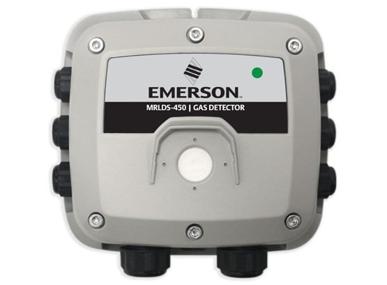 Figure 1 – Refrigerant Gas Detector
Component Overview
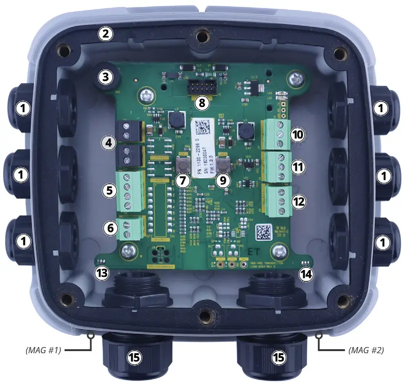 Figure 2 – Component Locations
| # | Component Description |
| 1 | M16 Cable Glands (x6) |
| 2 | Rubber Gasket |
| 3 | Internal Alarm Buzzer |
| 4 | Power Connections (x2) |
| 5 | Digital Connection (Modbus) |
| 6 | Analog Connection |
| 7 | Tactile Switch #1 |
| 8 | Ribbon Cable Connection (To Sensor) |
| 9 | Tactile Switch #2 |
| 10 | Relay 3 Connection (FAULT) |
| 11 | Relay 2 Connection (HIGH) |
| 12 | Relay 1 Connection (LOW) |
| 13 | Magnetic (Mag) Switch #1 |
| 14 | Magnetic (Mag) Switch #2 |
| 15 | M20 Cable Glands (x2) |
Table 1 – Component Descriptions
Product Specifications
| Size (HxWxD) | 6.5′ x 6.5″x 3.4″ (165 x165x87 mm) |
| Weight | 1.05 lbs (480g) |
| indicators | Multi-color status LEDInternal Alarm Buzzer 72dB @ 3.9″ (10 cm) |
| Alarm Delay | Configurable (0 to 15 minutes) |
| inputs | Tactile Switches (x2), Magnetic Switches (x2) |
| Outputs | Analog Output: 1 to 5V (default), 0 to 5V, 0 to 10V, 2 to10V, or4 to 20mA |
| Bluetooth | Bluetooth® Low Energy, BLE 4.2 |
| Modbus | Connection: RS-485 terminal block Baud Rate: 9,600 or 19,200 (default) Data Bits: 8Parity: None, Odd, or Even (default) Stop Bits: 1 (default) or 2Retry Time: 500 ms (minimum) |
| Power Supply | 19.5 to 28.5 VDC or 24 VAC ±20%; 4W |
| Wiring (Power) | 2-core cable, 16 to 28 AWG |
| Wiring (Relays) | 2-core cable, 16 to 28 AWG |
| Wiring (Modbus) | Recommended: Belden 3106A (or equivalent) 3-core, 2 twisted pair + ground, shielded cable with 120 0 characteristic impedance,16 to 28 AWG |
| Enclosure | Material: ABS Protection: IP66 |
| Temperature | Semiconductor: -40°F to 122°F (-40°C to 50°C)Electrochemical: Ranges vary by gas type and/or concentration, see the MRLDS-450 user manual (P/N 026-1316) for a full list of temperature ranges.Infrared: -40°F to 122°F (-40°C to 50°C)Catalytic Bead: -40 to 122°F (-40°C to 50°C) |
| Humidity | 5 to 90% RH, non-condensing |
| Pressure | 23.6 to 32.5″Hg (800 to 1,100 mbar) |
| Elevation | 0 to 6,560′ (3,000 m) altitude |
Table 2 – Product Specifications
Installation
IMPORTANT: The manufacturer of this product requires that a bump test or calibration be performed following installation to verify instrument functionality.STEP 1: Mount Gas Detector & Remove Lid CAUTION: DO NOT allow the lid/sensor to hang from the ribbon cable. Failure to comply may result in damage to the product.
- Mount the MRLDS-450 according to the product dimensions, maximum wiring lengths, and the following considerations:• Environment: the full range of environmental conditions when selecting a location.• Application: the specifics of the application (possible leaks, air movement/draft, etc.) when selecting a location.• Accessibility: the degree of accessibility required for maintenance purposes when selecting a location.• Target Gas: the specific gravity of the target gas when selecting the height of the instrument.
- Using a 5/32” (4mm) hex key/allen wrench (not included), remove the lid and disconnect the ribbon cable from the base.
- Set the lid and rubber gasket aside to be reinstalled later.
STEP 2: Wire Connections
WARNING: Ensure that all wiring connections are made BEFORE applying power.WARNING: Relays are rated for 0 to 30V. DO NOT apply main power onto these relays.IMPORTANT: Cable glands are meant to accommodate one cable. DO NOT use cable glands for more than one cable. IMPORTANT: If the analog output is 4 to 20mA, connect or short the connection to ensure the gas detector does not go into fault.
- Locate connections (Power, Analog, Modbus, Relays) and remove terminal blocks from the PCBA.
 Figure 3 – Locate Connections
 - Remove plugs from the corresponding M16 cable glands and pass the cable through the opening.
- Secure wires in each terminal block and, pressing firmly, reinstall the terminal block in the PCBA.
- Remove all excess cable from the housing before firmly securing the cable glands.
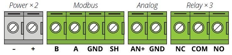 Figure 3 – Locate Connections
STEP 3: Reinstall Sensor and Connect LidCAUTION: DO NOT leave excess cable inside of the gas detector housing. Failure to comply may result in damage to the product. IMPORTANT: To achieve proper seal in the IP66 enclosure, the lid screws should be torqued to 15 to 20 lbf in (1.5 to 2.0 Nm).
- Reinstall the rubber gasket. Ensure that it is correctly seated by placing the side with two grooves face down and the edge with two bumps on the top. Figure 4 – Rubber Gasket Placement
- Reconnect the ribbon cable from the sensor to the PCBA as shown:Figure 5 – Ribbon Cable
- Ensure no cables are interfering with the sensor module and close the lid.
- Using a 5/32” (4 mm) hex key/Allen wrench, tighten the lid screws in an X tightening pattern:
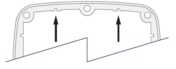 Figure 4 – Rubber Gasket Placement
 Figure 5 – Ribbon Cable
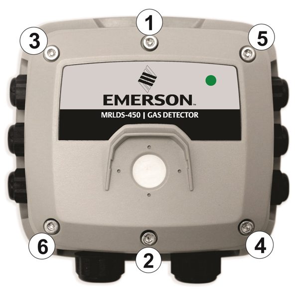
Figure 6 – Tightening Pattern
MRLDS-450 Network Setup for Site Supervisor and E2
For Modbus end-of-line termination, use 150Ω ohm resistor or termination block P/N 537-2711. Do not use MRLDS 120Ω ohm on-board termination with Site Supervisor or E2. IMPORTANT:
- For 24 VAC installations sharing a transformer in a daisy-chain configuration, the neutral polarity must be maintained for all instruments.
- 24 VAC power polarity must not be reversed.
- For a more robust system, a dedicated transformer for each MRLDS is recommended to prevent damage caused by wiring errors.
- Fasten terminal screws.
a. Site Supervisor Device and COMM Setup
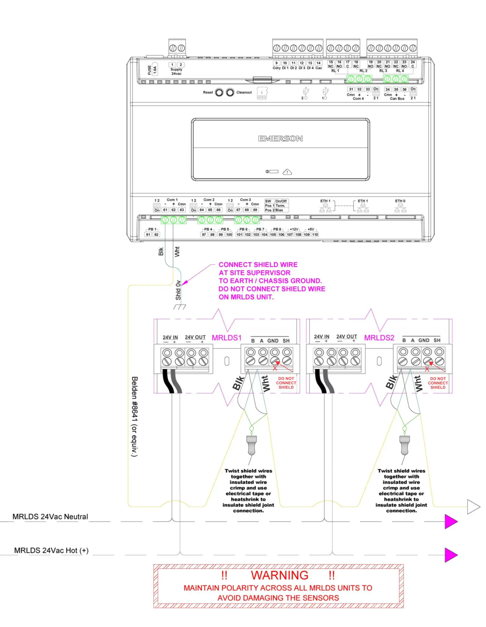 Figure 7 – Site Supervisor Setup
b. E2 Device and COMM Setup
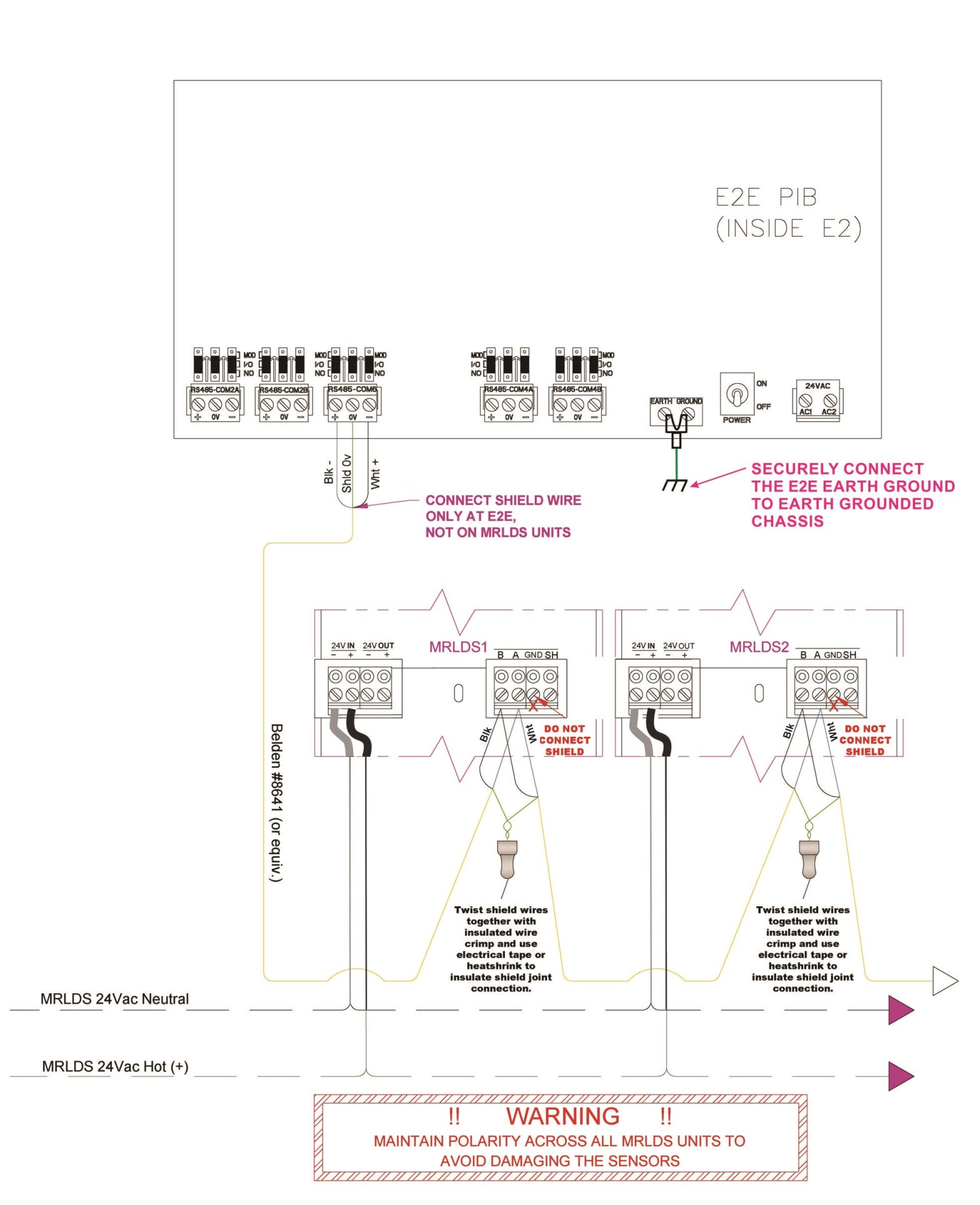 Figure 8 – E2 Setup
Connect MRLDS-450 to MRLDS-400 Series App (User Discretion)
The MRLDS-450 uses a smartphone application to allow users to interface with the gas detector.IMPORTANT: Default alias, passkey, and unlock code can be changed via the MRLDS-400 Series App’s configuration menu.
- Enable Bluetooth® discovery by tapping MAG#1 for 1 second. (After 10 seconds, the device will indicate that it is discoverable with audible heartbeat until it has been paired, the discovery has timed out or has been canceled.)
- Launch the MRLDS-400 App and click the Bluetooth® icon at the bottom of the screen to initiate a scan.
- Select the instrument (default is 18TMAE) from the list of available gas detectors.
- When prompted, enter the passkey (default is 123456).
- Go to Configure tab to set up the device. When prompted, enter unlock code to access device configuration (default is 1234).
 Figure 9 – App
| # | APP DESCRIPTION |
| 1 | Main Menu (App Settings) |
| 2 | Status (Gas Concentration) |
| 3 | Calibrate (Calibration/Bump Test) |
| 4 | Details (Instrument Information) |
| 5 | Disconnect Bluetooth® |
| 6 | Restart Connected Device |
| 7 | Test Mode (LED/Buzzer/Relays/Analog Output) |
| 8 | Device Configuration |
| 9 | Logs |
Table 3 – App Description
Operation Overview
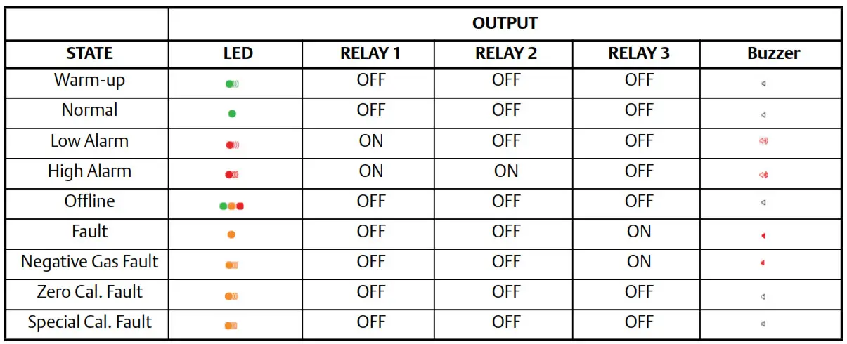 Table 4 – Outputs
Part Number and Ordering Information
| Emerson PIN | IP66, 3 x Relays, AnalogOutput, Modbus Output,Audible & Visual Alarms | SensorType | Emerson P/N | Replacement Sensor | SensorType |
| Gas Type and Detection Range | Pre-callbrated Sensor Modules | ||||
| 809-1040 | CO2 0-5,000ppm | IR | 809-1140 | CO2 0-5.000ppm | IR |
| 809-1041 | CO2 0-10.000ppm | IR | 809-1141 | CO2 0-10,000ppm | IR |
| 809-1047 | R404A 0-1,000ppm | SC | 809-1147 | R404A 0-1,000ppm | SC |
| 809-1048 | R407A 0-1,000ppm | SC | 809-1148 | R407A 0-1,000ppm | SC |
| 809-1049 | R410A 0-1,000ppm | SC | 809-1149 | R410A 0-1,000ppm | SC |
| 809-1050 | R22 0-1.000ppm | SC | 809-1150 | R22 0-1,000ppm | SC |
| 809-1056 | R448A 0-1,000ppm | SC | 809-1156 | R448A 0-1,000ppm | SC |
| 809-1058 | R513A 0-1,000ppm | SC | 809-1158 | R513A 0-1,000ppm | SC |
| 809-1066 | R422D 0-1,000ppm | SC | 809-1166 | R422D 0-1,000ppm | SC |
| 809-1068 | R449A 0-1,000ppm | SC | 809-1168 | R449A 0-1,000ppm | SC |
| MRLDS-450 Accessories | |||||
| 809-1190 | Calibration Adapter Kit | ||||
| 809-1191 | Horn + strobe 24VDC: blue lens | ||||
| 809-1192 | Horn + strobe 24VDC: amber lens | ||||
| 809-1193 | Horn + strobe 24VDC: red lens | ||||
| 809-1194 | Horn + strobe: blue lens: MP120K 120VAC adapter | ||||
| 809-1195 | Horn + strobe: amber lens: MP120K 120VAC adapter | ||||
| 809-1196 | Horn + strobe: red lens: MP120K 120VAC adapter |
Table 5 – Product Ordering Information
Scan the QR code to download the full user manual P/N 026-1316.

https://climate.emerson.com/documents/mrlds-450-manual-en-us-6005386.pdf
For the MODBUS setup of E2, please see the Quick Setup Guide P/N 026-4419.

https://climate.emerson.com/documents/026-4419-mrlds-450-application-in-e2-en-6436860.pdf
For Technical Support call 770-425-2724 or email [email protected]Document Part # 026-4417 Rev 2
This document may be photocopied for personal use.Visit our website at http://www.emerson.com for the latest technical documentation and updates.Join Emerson Technical Support on Facebook. http://on.fb.me/WUQRntFor Technical Support call 770-425-2724 or email [email protected]The contents of this publication are presented for informational purposes only and they are not to be construed as warranties or guarantees, express or implied, regarding the products or services described herein or their use orapplicability. Emerson Retail Solutions, Inc. and/or its affiliates (collectively “Emerson”), reserves the right to modify the designs or specifications of such products at any time without notice. Emerson does not assumeresponsibility for the selection, use or maintenance of any product. Responsibility for proper selection, use, and maintenance of any product remains solely with the purchaser and end-user.
 report this ad
EMERSON. CONSIDER IT SOLVED
References
[xyz-ips snippet=”download-snippet”]