EMERSON QSG4418R2 Multi-Zone Leak Detector and Display
Overview
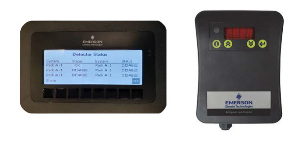
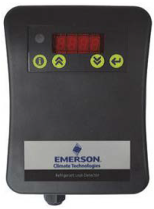
The Multi-Zone Leak Detector application and panel (P/N 851-4074) is a refrigerant leak detection system for monitoring refrigerant leaks in walk-in boxes, rack houses and machine rooms. Up to six (6) separate spaces (zones) can be monitored for refrigerant leaks with one panel. The system uses infrared-sensing technology to determine the concentration of refrigerant and reports this back to the main panel via analog signal wiring. The Visograph display provides a parts per million (PPM) reading. One MRLDS can be connected in each detection zone. The Multi-Zone Leak
Detector application is fully integrated with the E2E, has relay outputs for third-party devices, or can operate fully independent as a stand-alone device. The communication with E2E can use either Modbus RTU or BACnet MS/TP protocol. Each zone is capable of operating an audible and visible alarm based on user-defined alarm and spill setpoints. In addition, each zone has the ability to trigger a circuit shutdown in the event of a spill. The Leak Detector Panel comes equipped with a local strobe and horn. Optional hardware includes remote horn and strobes, MRLDS Halo-carbon and CO2 sensors, and battery backup panel. For a copy of the full Multi-Zone Leak Detector Application and Panel Manual, visit this link.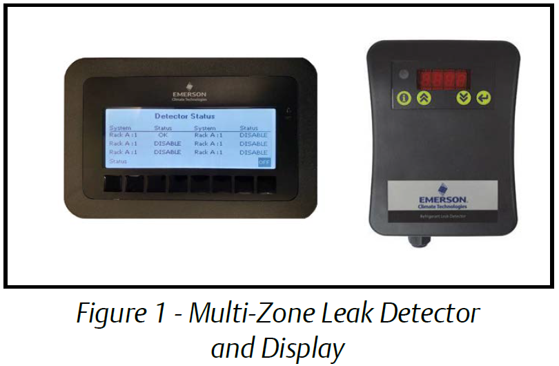
Configuring Modbus Settings
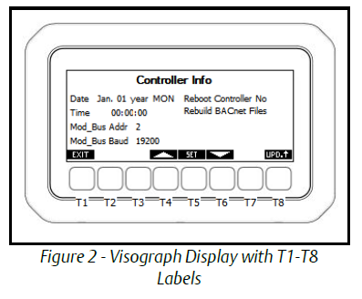
To set controller information from the Detector Status screen:
- Press and hold the T4 and T5 keys for three (3) seconds.
- The Setup screen will appear.
- Use the up and down arrow keys to highlight and select Controller Info and press SET.
- The Controller Info screen will appear.
- Use the up and down arrow keys to highlight and set the date, time, andModbus address.
- Press SET after each selection to save changes.
- After all Modbus settings have been configured, a controller reboot must be performed. Use the down arrow key to select No next to Reboot Controller, press SET to edit and use the arrow keys to select Yes. Press SET again. The controller will reboot and boot back up with the new settings applied.

Configuring BACnet Settings
To configure the BACnet Settings from the Detector Status screen:
- Press and hold the T4 and T5 keys for three (3) seconds.
- The Setup screen will appear.
- Scroll to 3. BACnet Settings and press SET to enter.
- MS/TP MAC: This parameter specifies the MS/TP network MAC address of the I/O Module. Each BACnet device on the bus must have a unique number here. Enter a unique number between 0-127 and press SET to save.
- Baud Rate: This parameter specifies how fast data is sent over the serial line. Set to match the baud rate of the serial port of the E2E controller.
- Max Master: This parameter defines value the highest allowable address for master nodes on the network. Determine the highest MS/TP MAC address used on the bus and set Max Master equal to this value. Example: If there are 40 controllers on the bus and the highest address is 40, set the max master of all 40 controllers to 40.
- Device ID: Enter the BACnet device identifier here. Enter a unique number for the MS/TP network in the range of 0-4, 194, 303.
- When at least one setting has been edited, a cancel option will appear above the T7 key and a save option above the T8 key. Pressing Cancel will revert the system back to the previous settings and no change will be applied.
Connecting Communication Wires
If the communication protocol between Leak Detector and E2E is using Modbus, connect the RS485 wiring to the RS485 slave terminal on the iPro controller, terminals 97, 98, 99. Thepolarity of the + and – wires is reversed between E2E serial port and the leak detector serial port.Note: The polarity of the Modbus connection between E2E and the Multi-Zone Refrigerant Leak Detector is reversed.
BACnet MS/TP
The BACnet MS/TP connection should be wired in a daisy chain topology: no star or T configurations are allowed. Connect the BACnet network cable to the three terminalconnectors on the E2E COM port you wish to assign as BACnet MS/TP. Connect the network cable to the leak detector on the RS485 master port terminals 94, 95, 96. Reverse the polarity of +/- on the RS485 cable between the E2E serial port and the leak detector serial port. Emerson specs General Cable 92454A (Emerson P/N 135-0600) shielded twisted pair cables for use as BACnet MS/TP wiring.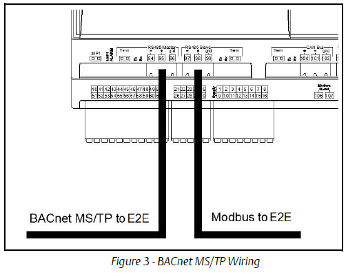
For a full copy of the Multi-Zone Leak Detector Application and Panel Manual (P/N 026-1313), scan the QR code.
This document may be photocopied for personal use.Visit our website at http://climate.emerson.com for the latest technical documentation and updates.Join Emerson Technical Support on Facebook. http://on.fb.me/WUQRntFor Technical Support call 833-409-7505 or email ColdChain.[email protected]The contents of this publication are presented for informational purposes only and they are not to be construed as warranties or guarantees, express or implied, regarding the products or services described herein or their use or applicability. Emerson reserves the right to modify the designs or specifications of such products at any time without notice. Responsibility for proper selection, use and maintenance of any product remains solely with the purchaser and end-user. ©2021 Emerson is a trademark of Emerson Electric Co.![]()
References
[xyz-ips snippet=”download-snippet”]