
![]()
EMERSON Recommended Contactor Selection for Three Phase Motor Control User Guide
Revision Tracking R19 May 2020Added 3D Compressors in contactor selection list on Table 6 and Table 7Improved 4D, 6D and 8D reference tables to higher resolution
© 2020 Emerson Climate Technologies, Inc.
Safety Instructions
Copeland compressors are manufactured according to the latest U.S. and European Safety Standards. Particular emphasis has been placed on the user’s safety. Safety icons are explained below and safety instructions applicable to the products in this bulletin are grouped on Page 3. These instructions should be retained throughout the lifetime of the compressor. You are strongly advised to follow these safety instructions.
Safety Icon Explanation
![]()
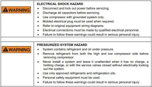
Instructions Pertaining to Risk of Electrical Shock, Fire, or Injury to Persons
Safety Statements
- Refrigerant compressors must be employed only for their intended use.
- Only qualified and authorized HVAC or refrigeration personnel are permitted to install commission and maintain this equipment.
- Electrical connections must be made by qualified electrical personnel.
- All valid standards and codes for installing, servicing, and maintaining electrical and refrigeration equipment must be observed.
Introduction
1. Introduction: The contactor is one of the most important parts of any motor control circuit. It is vital that compressor applications for contactors are well understood and that the contactor is correctly sized for the load. An incorrectly sized contactor can destroy the best compressor.
As a general rule, contactors are designed for general purpose or definite purpose (specific use). Contactors can be further subdivided by listing categories for their use such as light or resistance (electric heating or lighting) loads and motor loads according to their severity.
NEMA Rated General Purpose ContactorsGeneral purpose contactors are built for the severe industrial use. They are usually designed for a minimum life of over 1,000,000 electrical cycles on most types of motor loads. General purpose contactors rated in the United States usually conform to NEMA (National Electrical Manufacturers Association) ratings. NEMA has standardized on electrical sizes of motor controls to make the manufacturing of these devices more universal. A person who has one manufacturer’s NEMA size 1 contactor or motor starter can interchange his contactor with a NEMA size 1 from another vendor and be assured that the controller has been designed for the same broad spectrum of loads.
IEC Rated ContactorsThere are many European test organizations for electrical controls. In order to obtain some degree of regulatory agency standardization, the International Electrotechnical Committee (IEC) was formed. If the requirements of this authority are met, an electrical device will meet most European test standards.
IEC contactors are listed in four basic utilization categories; ‘AC1’ through ‘AC4’. These categories describe the requirements for switching electrical loads from those with light inrush currents (resistive) to heavy duty motor applications.
An IEC designed contactor may be tested to any amperage or horsepower rating in any ‘AC’ category the manufacturer chooses.
IEC tests are not designed specifically for hermetic refrigeration motors as are the ARI (Air Conditioning and Refrigeration Institute) tests. The ARI tests are, in part, used for Emerson Climate Technologies standards.
ARI test requirements for compressor contactors fall between IEC categories ‘AC3’ and ‘AC4’. The ‘AC3’ rating is for starting of squirrel cage motors with locked rotor currents equal to eight times rated load amps, with voltages to 600VAC, but stopping the motor only at Rated Load Current, when the motor is up to speed. This means there are no ‘AC3’ provisions for a contactor to open the compressor circuit under locked rotor conditions.
The ‘AC4’ rated contactor is life tested, making and breaking motor locked rotor circuits at eight times Rated Load Amps with voltages to 600VAC. Because of the severity of this test, ‘AC4’ devices are not normally selected for refrigeration compressor loads.
At the end of each series of IEC contactor tests, the manufacturer typically publishes contactor life curves. These curves allow the user to estimate the contactor’s mechanical life and electrical contact life, based on his application, rather than on the contactor nameplate rating. These curves help the user to make a determination of the life expectancy of his contactor based on his application.
Refrigeration compressor users commonly estimate IEC contactor life expectancy by using a combination of ‘AC3’ and ‘AC4’ ratings. This combination results in a shorter contactor life expectancy than the manufacturer’s ‘AC3’ published rating curve, but it is more representative of actual field conditions.
The user must use these curves carefully. IEC has different test requirements for rating (nameplate) verification than for contact life curves.
The user should also verify the type of short circuit protection required, since this can vary with the IEC manufacturer.
Definite Purpose ContactorsTo meet the needs of the refrigeration and air conditioning industry, electrical equipment manufacturers have developed definite purpose contactors. These contactors have been designed specifically for loads where their life can be statistically predetermined by their application. Definite purpose contactors normally have a lower initial cost compared to NEMA and IEC devices.
Although their cost is less, definite purpose compressor contactors must still be designed to meet harsh conditions such as rapid cycling, sustained overloads, and low system voltages. They must have contacts large enough to dissipate the heat generated by the compressor load currents, and their contact materials must be selected to prevent welding under starting and other LRA (Locked Rotor Amperage) conditions.
Three Phase, Three Contact, Contactor
Requirement
Emerson contactor test requirements for both electrical application ratings and life expectancy, on three phase applications, are based on both making and breaking all three legs of a three-phase power supply. Similarly, recommendations for proper contactor sizing are based on this testing criteria, and the expectation that the contactor will be applied so as to break all three legs.
On small single-phase compressors, it has been common practice for many years to control motor operation by making and breaking only one leg of the two-leg power supply through a relay or pressure control contact.
Since the voltage involved is either 115V or 230V, and the current flow relatively small, the control relay or pressure switch contact points have satisfactory lives and field problems are minimal.
From time to time, for reasons of economy, consideration is given to applying three phase motors in a similar fashion using a contactor with only two contact points to break two legs of the three-phase power supply, while leaving the third leg connected to the supply. Using two leg control, particularly on systems having a supply voltage of 460 Volts or higher, results in a serious field safety hazard. If this two-contact approach is used, a danger will exist for service or operating personnel who fail to identify the unbroken power lead.
There is also some evidence that unexplained air conditioning compressor motor failures on spring startup were caused by winter lightning strikes finding a path through the compressor motor contactor to the compressor by way of the unbroken line.
In the best interests of both Emerson and the user, Emerson only lists those contactors that break all three legs of a three-phase circuit. For reasons of safety and reliability, Emerson does not recommend the two-leg break approach and would particularly discourage any two leg break for power supplies greater than 240VAC.
Amperage Ratings of NEMA and Definite Purpose ContactorsGeneral Purpose (NEMA) rated contactors are listed by sizes that are generally related to motor horsepower groupings. They are also rated in current, a more useful rating for compressors. DP (Definite Purpose) contactors, on the other hand, are usually listed for current alone, although occasionally a manufacturer qualifies his contactor for horsepower ratings. The Definite Purpose contactor has less ability to handle inrush (Locked Rotor Amps or LRA) currents than does the General-Purpose contactor. The amount of inrush current each DP contactor can carry is usually inversely proportional to the system voltage, while General Purpose contactors keep the same inrush current ratings with system voltages as high as 600VAC.
FLA (Full Load Amps) is the term used by most industries to represent a maximum running current rating. Compressor manufacturers use RLA (Rated Load Amps).
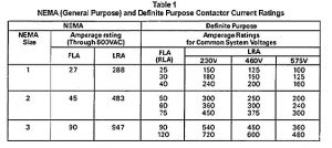
The inrush and applicable amperage rating for several NEMA size General Purpose contactors and comparable, DP contactors are shown in Table 1. Notice the much broader selections of Definite Purpose contactors that enable them to be more closely tailored to the load.
Caution! Most contactors have a resistive rating as well as a motor rating. The resistive rating is higher in amperage value than the motor rating amperage value. This is because a resistive load is not called on to make and break motor currents. You must use motor load ratings for motor loads.
Table 1 shows the differences between a current rated general-purpose contactor, and a definite purpose contactor. Notice that the general-purpose contactor has no voltage limitations on its inrush or LRA (locked rotor amp) rating, while the definite purpose goes by the ‘six-five-four’ rule. This rule means the contactor’s LRA rating for a load is six times the RLA for 230V, it is five times for 460V, and four times for 575V.
Establishing the Compressor Contactor LoadU.L. (Underwriter’s Laboratories), tests compressor motors to verify their contactor requirements and overcurrent protection needs. Their tests are designed to be in conformance with Articles 430 and 440 of the NEC (National Electric Code). These articles, in part, outline the requirements of contactors in compressor motor circuits.
In general, U.L. requires that a maximum continuous running current rating be established for each compressor for each application. By definition the maximum continuous current is that current drawn just prior to protector trip. In effect, this extreme continuous current value is then used to establish a running current value for the compressor called RLA (Rated Load Amps). Article 440 of the NEC sets the Maximum Continuous Current (MCC) rating of a compressor motor at 156% of its RLA value.
The National Electric Code definition of RLA is really applicable only if a compressor is installed in a complete system. If only this definition of the compressor load was used, and a compressor was to be rated only after it was installed in a condensing unit or a system, there would be a huge number of possible Rated Load Amp values.
As a practical matter, U.L. accepts the compressor Rated Load Amps (RLA) value in lieu of testing each condensing unit with the wide variety of evaporators to which it might be applied.
Since there are no test criteria to insure contactor operation at 156% of its RLA rating, there is no assurance that a contactor can stand prolonged exposure to an overload of the magnitude which would be incurred just prior to a protector trip.
Therefore, Emerson Climate Technologies has established a rated load current for all pilot circuit protected compressors at a more conservative value. Maximum Continuous Current for all Copeland® compressors is 140% of Rated Load Amps. It is a specification of the Emerson warranty that the contactor size must not be less than the Emerson nameplate Rated Load Amp value.
Emerson Contactor Application SpecificationsThe following Emerson specifications are based on contactor ratings as listed with U.L.
- The contactor must meet the operational and test criteria in ARI (Air Conditioning and Refrigeration Institute) Standard 780- 78, Standard for Definite Purpose Contactors.
- The contactor must be certified by the manufacturer to close at 80% of the lowest nameplate voltage at normal room temperatures. (166 Volts for contactors used on 208/230 Volt rated equipment.)
- On single contactor applications, the rating of the contactor for both full load amperes and locked rotor amperes (LRA) must be greater than the corresponding nameplate amperage rating of the compressor motor RLA plus the nameplate amperage ratings of any fans or other accessories also operated through the contactor.
- For two contactor applications, each contactor must have a part winding locked rotor rating equal to or exceeding the half winding locked rotor rating of the compressor.
Very often, since half winding LRA is larger than 50% of the compressor full winding LRA, and definite purpose contactors are sized in part by the locked rotor rating, the two contactors needed to meet the part-winding locked rotor requirement will have a combined full load rating in excess of the compressor nameplate full load rating.
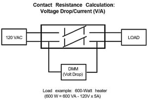
Compact DP (Definite Purpose) Contact Resistance Measurements and Continuity Verifications
Continuity of the main power poles can be directly attributed to the relationship between the coating buildup (oxidation/debris) on the contact surfaces, contact resistance, and shelf life. Therefore, measuring resistance across contacts with a Digital Multi-Meter (DMM) will often give false readings (even open circuit) since there is not enough power to break through the surface coating.
The following procedures are recommended for measuring contact resistance and for verifying continuity:
Resistance MeasurementIn order to burn through the oxidation, it is recommended to test the contactors using 120 or 230 VAC at 10 Amps and calculate the contact resistance by Volts / Amps. The reason to select 10A as the test load current is because for most contactors the rated operating current is usually 9A or greater. A test current of 10A can cover most contactor sizes. See measurement example below:
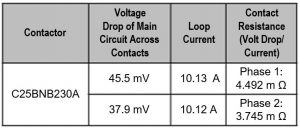
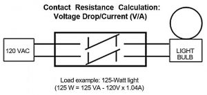
Although 10A is the recommended current, 5A is the minimum amperage that should be used for resistance calculation. Example of 5A load below:
Continuity Verification of ‘New’ ContactsEven ‘new’ contacts can be affected by oxidation or contamination due to handling, environment, and time elapsed while being stocked after manufacture. Therefore, continuity should be verified with a load. A relatively reliable and easy way to do this is with a light bulb. With a 120-vac source, a 100 watt or higher wattage light should be used to get a load current of near or over 1 amp. (100 w/ 120 vac = .83 amps.) Due to the relatively lower current than what’s used for resistance measurement, it may take several operations of opening and closing the contactor to break through the surface coating to get continuity and the light may ‘flicker’ while this is happening. (Note: There may be times when the low current is not enough to break through the coating). See set-up example below:
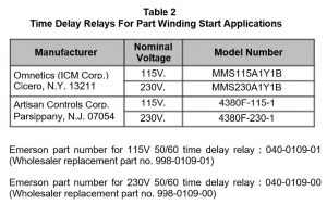
Time Delay RelaysFor part winding start applications, a time delay relay is required between contactors with a setting of 1 second plus or minus 1/10 second. The operation of a delay relay can be affected by low voltage.
In order to insure reliability, time delay relays listed as meeting Emerson specifications for nominal 208/230 Volt control systems must be guaranteed by the manufacturer to function properly at 170 Volts in a -40F ambient. See Table 2.
Approved Vendors of Time Delay Relays and ContactorsThe following time delay relays are listed by U.L., have met Emerson’s performance specifications, and to the best of Emerson’s knowledge have had a record of satisfactory field experience.
However, since Emerson does not continually monitor these devices and has no control over the materials or workmanship involved in manufacture, any defects must be the responsibility of the manufacturer.
The Emerson warranty does not extend to external electrical components furnished by others, and the failure of such components resulting in compressor failure, will void the compressor warranty. In addition, Emerson reserves the right to issue credit to Wholesalers for 4, 6, or 8 model semi-hermetic service compressors that are determined to have a single-phase motor burn caused by an Emerson contactor. Single phase motor burns are not the result of manufacturing defects. See Table 3 for a description.
Four Steps to Select a Compressor Contactor
- Determine the system voltage.
- Determine if the compressor is to be started by Full Voltage or Part-Winding (one contactor or two contactor start).
- Obtain the compressor RLA and LRA values from Table 4 for medium and low temperature applications or Table 5 for high temperature applications at the end of this bulletin, from the compressor nameplate, or from Emerson Climate Technologies specifications.
- Check Emerson Approved Contactor Description. Refer to Table 4 for contactor requirements for Medium and Low temperature applications or Table 5 for high temperature applications.
If the compressor is not listed in a table, the contactor can always be sized for full voltage starting by selecting a contactor of the next amperage rating larger than the compressor’s rated load amperage (RLA), and then checking its LRA requirements against the rating of the chosen contactor.
TESTS FOR CONTACTOR QUALITY
Definite Purpose Contactor RequirementsOf the two general requirements all motor contactors must meet, dissipating the heat generated in the contacts while running, and cycling on and off under locked rotor conditions, the locked rotor cycling requirement is the hardest to understand. The compressor normally undergoes a locked rotor condition, at startup, for such a very short period of time that it is difficult to measure in the field. Yet, it is under this condition that the contactor ‘points’ are subjected to their maximum currents. If two contactors are used for starting the compressor (‘parallel winding start’ or ‘part winding start’), the situation is further complicated by the fact that when only 1/2 of the motor winding is energized, the locked rotor current drawn is in excess of 1/2 of the full motor locked rotor current because of the inductive transformer effect of the non-energized winding.
Because definite purpose contactors are so critical to the successful operation of a compressor system, Emerson Climate Technologies has worked with both U.L. and ARI to develop contactor ratings and methods of test. There are very important tests that relate to the life of the contactor. Emerson subscribes to, and the contactor requirements follow, the harsher of the two tests recommended by the two organizations.
- The Mechanical Life TestARI requires that the contactor shall have no mechanical malfunction after 500,000 cycles with no electrical load. This test checks the moving parts of a contactor and its coil.
- Endurance Test Under Rated LoadARI states that the contactor must withstand 200,000 starting cycles with no failure, when making its rated locked rotor current and breaking 125% of its rated load current.
- Locked Rotor Endurance TestFor refrigeration and air conditioning applications with automatic reset pilot duty protection and for single contactor applications, ARI recommends a locked rotor test, based on the contactor making and breaking locked rotor amps, of 10,000 cycles.
- Part Winding and Two Contactor TestFor part winding or two contactor applications, the U.L. requirement is based on 30,000 cycles making full load and breaking locked rotor current. This is a very difficult test to pass. This test requirement can result in a substantial difference in the locked rotor rating of the contactor. Some contactors cannot successfully complete this test without lowering their inrush current ratings. These contactors are listed as derated to 80% of their single contactor inrush current rating for two contactor (which includes part winding) applications.
- Low Voltage Pull In TestThe marginal nature of the power supply in some sections of the United States can result in dangerously low voltages during heavy demand periods.On 208 Volt systems, which appear to be the most critical, the supply voltage at the utility may be as low as 191 Volts, and if the distribution and installation wiring is heavily loaded, it is possible that voltage at the compressor contactor coil may be well below 180 volts during the starting period when high inrush current is drawn.Unless the contactor coil has adequate capability to pick-up (close its contacts), the low voltage condition can cause contact chatter, and potential contactor and compressor failure. In order to insure increased reliability, definite purpose contactors listed as meeting Emerson specifications with coils for nominal 208/230 Volt power must be guaranteed by the manufacturer to give a clean pick-up at 166 Volts at normal room temperature.Any chattering or failure of a contactor to function properly under low voltage conditions should be investigated. If the voltage supplying the contactor is too low, or the voltage ‘drops’ to an unacceptable level when the contactor is energized, the system voltage should be corrected.
The Contactor and Motor Overload ProtectionContactors play a role in any compressor overload protection scheme, but they are particularly important when they are part of pilot operated protection systems. When the compressor pilot or control circuit contains the contact of a modern electronic overload protector, the protector, in conjunction with a properly operating contactor of the correct size, provides an excellent motor safeguard. The protector accurately senses a change in motor temperature caused by a mechanical or an electrical overcurrent problem and signals the contactor coil to remove the compressor from the power supply. Despite this protection, motor burnouts attributed to power supply problems continue to be a source of motor failure. Improperly sized contactors can contribute to this problem, even if it does not originate with them.
Power Supply ProblemsAn all too common power supply problem is the loss of one phase in the lines from the secondary of the power supply transformer to the compressor. If the motor is stopped this ‘single phasing’ will cause the compressor to draw heavy rotor currents but be unable to start.
If the compressor is running at the time of the fault, it will continue to run but with a large current overload. The motor windings will of course rapidly overheat, and the motor protector will signal the contactor coil to remove the compressor from the line. But, as soon as the compressor motor windings cool down to normal operating temperatures, the protector will signal the compressor to restart, but the motor is unable to restart generating locked rotor current which will cause the protector to trip again. No compressor motor is designed to indefinitely cycle on a single-phase condition.
During the sustained locked rotor condition, the motor not only overheats rapidly but the motor windings undergo a continuing mechanical stress that is far beyond their starting and running design. If the problem exists over a long period of time the motor life will be shortened, and the protector will fail. The protector will either fail open, preventing a compressor start, or it will fail closed. If the protector fails closed, the motor will lose all protection and will burn out during the next single-phase cycle.
Because of unbalanced loading on all three voltage lines, single phasing can also produce the side effect of erratic voltages in the control circuit. These very rapid fluctuations can cause contactor chatter. The chattering contactor continually connects the motor to the line, then disconnects it. The motor is subjected to heavy magnetic torqueing of its stator windings as well as heavy inrush currents as it is needlessly cycled on and off. This condition is one of the most destructive to a motor. Motor windings move and rub together each time the contactor closes, and in a short time under these rapid cycling conditions winding insulation fails, windings are shorted together, and the destruction continues until the motor fails. This is a source of motor failures against which the compressor overload system was not designed to protect. In addition to the motor stress, the chattering contactor is taking a beating. No contactor can last long under this condition. After a time, even the best contactor’s coil will fail. If the contactor’s coil fails, it can seize the contactor armature in such a way that all contacts are not closed or not opened evenly, with single phasing as a result.
If the contactor has been undersized, its contacts will be unable to withstand the arcing and high temperatures generated by the extreme cycling or ‘machine-gun’ effect of an erratic control circuit voltage, and they will very likely weld together or become dislodged from their contact carrier. Welded contacts will create a permanent single-phase condition that makes the overload protector continuously cycle on and off . Dislodged contacts force the copper contact carriers of the contactor to try to make and break heavy electrical currents and they will also weld. When welding occurs, the contactor will perpetuate the single-phase condition through its welded or missing contacts.
After a single-phase condition has been corrected, the contactors and relays of the control circuit should be inspected for damage if they could have been adversely affected. If a compressor contactor fails with its contacts or contact carrier welded, the motor can also fail at a later time even though the power supply problem has been corrected, and in addition a hazardous condition has been created since the system safety controls cannot remove the compressor contactor from the line in case of an overload
Primary Phase FailureThe effect of an open phase in the primary circuit of a power transformer depends on the type of transformer connection. Where both primary and secondary windings are connected in the same fashion, wye-wye or delta-delta, a fault in one phase of the primary will result in a low current in one phase of the secondary, and high currents in two phases, with results similar to the simple load circuit single phase condition.
But in wye-delta or delta-wye connected power transformers, an open circuit or single phase on the primary side of the transformer will result in a high current in only one phase of the motor with low currents in the other two phases.
Under locked rotor conditions, the high phase will draw an amperage slightly less than nameplate locked rotor current, while the other two legs will each draw approximately 50% of that amount. Under operating conditions, the current in the high phase could be in excess of 200% of full load amperes, depending on load, while the current in the other two legs will be slightly greater than normal full load amperes.
Unbalanced Supply VoltageA properly wound three phase motor connected to a supply source in which the voltages in each phase are balanced at all times will have nearly identical currents in all three phases.
The differences in motor windings in modern motors are normally so small that the effect on amperage draw is negligible. Under ideal conditions, if the phase voltages were always equal, a single motor protector in just one line would adequately protect the motor against damage due to an excessive running overcurrent draw.
As a practical matter, balanced supply voltages are not always maintained, so the three-line currents will not always be equal.
The effect of unbalanced voltages is equivalent to the introduction of a ‘negative sequence voltage.’ This exerts a force opposite to that created with balanced voltages.
These opposing forces will produce currents in the windings greatly in excess of those present under balanced voltage conditions.
Voltage unbalance is calculated as follows:
% VU (Voltage Unbalance) = (100 x Maximum Voltage Deviation from the Average Voltage of the three phases)/ Average Voltage of the three phases
As an example, a nominal 230V 3PH power source, produces the following voltages at the terminals of a three-phase compressor:
L1-L2 = 220V, L1-L3 = 230V, L2-L3 = 216V
Using the percentage voltage unbalance formula, we get the following:
Average voltage = (220V + 230V + 216V)/3 = 222V Maximum Deviation = 230 – 222 = 8% voltage unbalance = (100 x 8)/222 = 3.6 %
As a result of the voltage unbalance, the locked rotor currents will be unbalanced to the same degree. However, the unbalance in load currents at normal operating speed may be from 4 to 10 times the voltage unbalance, depending on the load. With the 3.6% voltage unbalance in the previous example, load current in one phase might be as much as 30% greater than average line current being drawn.
The NEMA Motors and Generators Standards Publication states that the percentage increase in temperature rise in a phase winding resulting from voltage unbalance will be approximately two times the square of the voltage unbalance.
% Increase in Temperature = 2 x Voltage Unbalance²
Using the voltage unbalance from the previous example, the % increase in temperature can be estimated as follows:
% Increase in Temperature = 2 x (3.6 x 3.6) = 25.9%
As a result of this condition, it is possible that one phase winding in a motor may be overheated while the other two have temperatures within normal limits.
A common source of unbalanced voltage on a three-phase circuit is the presence of a single-phase load between two of the three phases.
A large unbalanced single-phase load, for example a lighting circuit, can easily cause sufficient variations in
motor currents to endanger the motor. If at all possible, this condition should be corrected by shifting the single-phase load as necessary. Supply voltages should be evenly balanced as closely as can be read on a commercial voltmeter.
A national survey by U.L. indicated that 36 out of 83 utilities surveyed, or 43%, allowed voltage unbalance in excess of 3%, and 30% allowed voltages unbalance of 5% or higher.
In the event of a supply voltage unbalance, the power company should be notified of such unbalance to determine if the situation can be corrected.
Solid state protection provides excellent temperature characteristics and will protect the motor even with unbalanced current. However, consistently high current in one or two phases can materially shorten the motor life and may be the source of failure.
It is important that the system operator be made aware that to prevent unnecessary failures additional circuit current and voltage devices may be required especially if the power supply has had a problem history. The operator should also understand that any replacement under warranty of a compressor failing due to a motor burn is contingent on the proper application of a contactor meeting Emerson specifications. It is vital to the compressor that contactors are properly applied.
Table 3 – Emerson Approved Contactors
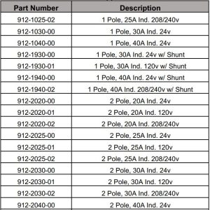
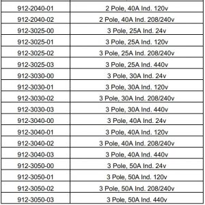
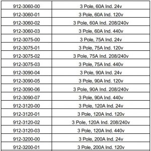
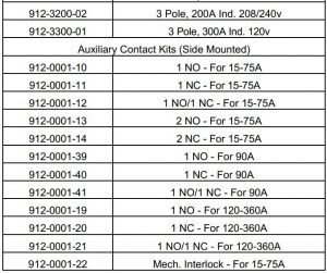
Table 4 – Contactor Specifications & Selection Guide – Low and Medium Temp
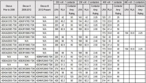
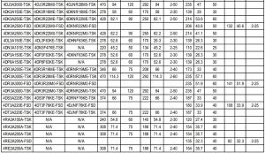
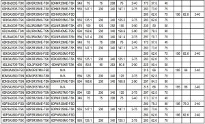
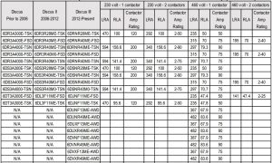

*Please reference OPI for additional refrigerant and application information.**Models with a “D” or “X” in the fourth digit of the compressor nomenclature are digital. Please reference the baseline model, which would have an “N” or “3” in the fourth digital of the nomenclature, for contactor specification and selection
RLA – Rated load amps.Note! RLA value is highest rated value for each compressor. To obtain the specific RLA based on refrigerant & application check the Online Product Information or Emerson Product Selection Software.LRA – The current drawn by a motor which is “locked” and cannot rotate.
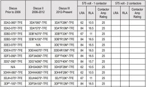
Table 5 – Contactor Specifications & Selection Guide – High Temp

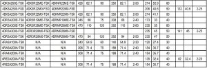
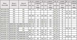
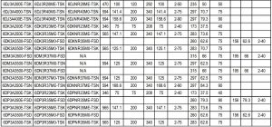
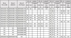
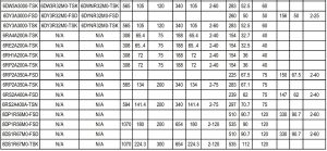
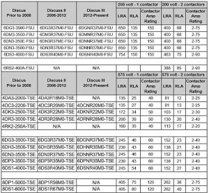
Table 6 – Contactor Specifications & Selection Guide for 3D Compressors – Low and Medium Temp
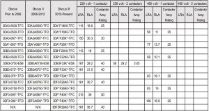
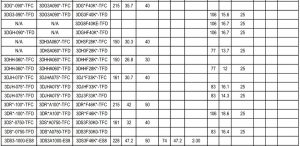
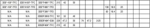
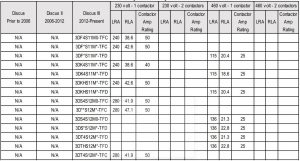
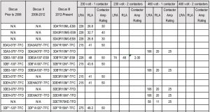
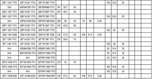
Table 7 – Contactor Specifications & Selection Guide for 3D Compressors (575V)

- Please reference OPI for additional refrigerant and application information.
- Models with a “D” or “X” in the fourth digit of the compressor nomenclature are digital. Please reference the baseline model, which would have an “N” or “3” in the fourth digital of the nomenclature, for contactor specification and selection.
The contents of this publication are presented for informational purposes only and are not to be construed as warranties or guarantees, express or implied, regarding the products or services described herein or their use or applicability. Emerson Climate Technologies, Inc. and/or its affiliates (collectively “Emerson”), as applicable, reserve the right to modify the design or specifications of such products at any time without notice. Emerson does not assume responsibility for the selection, use or maintenance of any product. Responsibility for proper selection, use and maintenance of any Emerson product remains solely with the purchaser or end user.
© 2020 Emerson Climate Technologies, Inc.
[xyz-ips snippet=”download-snippet”]