
Quick Start Guide
00825-0600-2654, Rev ADMarch 2021
Rosemount™ 214A2A Sensor
ROSEMOUNT ![]()
Quick Start Guide March 2021
Safety messages
NOTICE
This guide provides basic guidelines for Rosemount™ 214A2A Sensor models.Complications can arise if sensors are assembled to transmitters that have different, but compatible approval option codes. Be aware of the following situations:
- If an I.S. approved sensor is ordered with a housing, a transmitter enclosed in that housing may have a different I.S. approval rating. Refer to the transmitter IS certificate if applicable.
- If a sensor and transmitter have different certifications, or if either has more certifications than the other, installation must comply with the most restrictive requirements required by either component. This is especially (but not exclusively) relevant when combination approvals are ordered on either the sensor or transmitter. Review certifications on both the sensor and transmitter for installation requirements and ensure installation of the sensor/transmitter assembly complies with a single certification that is shared by both of these components and that meets the requirements of the application.
 WARNING
Explosions
Explosions could result in death or serious injury.
Installation of sensor in an explosive environment must be in accordance with appropriate local, national, and international standards, codes, and practices.
Conduit/cable entriesUnless marked, the conduit/cable entries in the housing use a ½14 NPT thread form. Entries marked “M20” are M20 × 1.5 thread form. On devices with multiple conduit entries, all entries will have the same thread form. Only use plugs, adapters, glands, or conduit with a compatible thread form when closing these entries.When installing in a hazardous location, use only appropriately listed or Ex certified plugs, glands, or adapters in cable/conduit entries.Only use plugs, adapters, glands, or conduit with a compatible thread form when closing these entries.
Physical accessUnauthorized personnel may potentially cause significant damage to and/or misconfiguration of end users’ equipment. This could be intentional or unintentional and needs to be protected against.
Physical security is an important part of any security program and fundamental to protecting your system. Restrict physical access by unauthorized personnel to protect end users’ assets. This is true for all systems used within the facility.
ContentsWiring diagram for RTDs………………………………… 3Wiring diagram for thermocouples…………………… 4Product certifications……………………………………….. 5Declaration of Conformity………………………………. 12
March 2021 Quick Start Guide
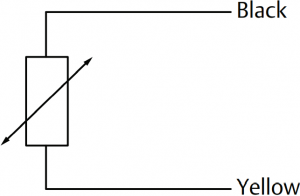
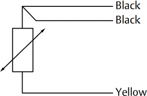
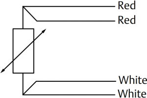
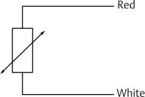
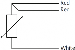
1 Wiring diagram for RTDs
Figure 1-1: RTD Lead Wire Configuration per IEC 60751 – Single Element
2-wire 3-wire 4-wire
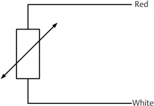
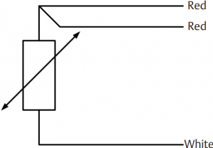
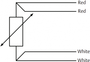
NoteTo configure a single element, 4-wire RTD as a 3-wire system, connect only one white lead. Insulate or terminate the unused white lead in a manner that prevents shorting to the ground. To configure a single element, 4-wire RTD as a 2-wire system, connect matching colored wires first and then connect the paired wires to the terminal.
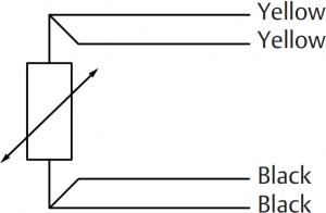
Figure 1-2: RTD Lead Wire Configuration per IEC 60751 – Dual Element
2-wire 3-wire 4-wire
Quick Start Guide 3
Quick Start Guide March 2021
2 Wiring diagram for thermocouples
Figure 2-1: Thermocouple Lead Wire Configuration
Single thermocouple, 2-wire
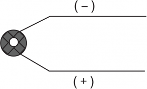
Dual thermocouple, 4-wire
Table 2-1: Thermocouple Wire Color
|
IEC 60584 Themocouple |
ASTM E230 Thermocouple |
|||
| Type | POS (+) | NEG (-) | POS (+) | NEG (-) |
| E | Violet | White | Purple | Red |
| J | Black | White | White | Red |
| K | Green | White | Yellow | Red |
| N | Pink | White | Orange | Red |
| T | Brown | White | Blue | Red |
March 2021 Quick Start Guide
3 Product certifications
Rev 1.0
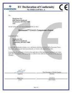
European Directive information
A copy of the EU Declaration of Conformity can be found at the end of the Quick Start Guide. The most recent revision of the EU Declaration of Conformity can be found at Emerson.com/Rosemount.
3.1 E1 ATEX Flameproof
Certificate DEKRA 20ATEX0045XStandards EN 60079-0:2012+A11:2013, EN 60079-1:2014Markings ![]() II 2 G Ex db IIC T6…T1 Gb
II 2 G Ex db IIC T6…T1 Gb
3.2 E7 IECEx Flameproof
Certificate IECEx DEK 20.0023XStandards IEC 60079-0:2011, IEC 60079-1:2014-06Markings Ex db IIC T6…T1 Gb
The process side of the assembly is for the responsibility of the user. The assembly should always be used in a closed system.
No changes are allowed on the product.
Flameproof enclosure “d”;In type of explosion protection Ex d, certified entry devices shall be used that are suitable for the application and correctly installed.
Unused openings shall be closed by suitable blanking elements. Only suitable thread adapters shall be used. Thread adapters will not be used in combination with blanking elements.
Verify the entry size (M20, ½-in. ¾-in., etc).
The degree of protection of IP66 or IP67 to EN 60529 is only achieved if certified Ex d entry devices are used that are suitable for the application and correctly installed.
Only use approved inserts.
For external earthing or bonding connection of the connection head a cable lug shall be used so that the conductor is secured against loosening and twisting and that contact pressure is permanently secured.
Quick Start Guide 5
Quick Start Guide March 2021
3.2.1 Electrical data
Thermocouple sensing element 5 Vdc, 10 mARTD sensing element 5 Vdc, 10 mATransmitter data max. 45 Vdc, max 50 mA, max 1.9 W
For the electrical data of a sensor in combination with a transmitter, see electrical data of the transmitter.
Special Conditions for Safe Use:
- Ambient temperature range of sensor assembly with PTFE cable insulation: -40 to +80 °C, and for Silicon cable insulation: -25 to +80 °C.
- Service temperatures wire: Silicon -25/+160 °C, PTFE -40/+180 °C.
- Service temperatures connection box and head: -40 to +80 °C, except for T6 maximum temperature is 70 °C.
- When the process temperature range exceeds the service temperature range of the connection head, the connection box and the cable (the maximum ambient temperature (Tamax) is +80 °C except for T6 (Tamax) is +70 °C), it shall be verified by on-site temperature measurements, taking the worst case conditions into account, that the service temperature of these parts does not exceed the range as listed above.
- The measurement report with the conclusions shall be filed together with the certificate to prove that this condition is met.
- For information about the dimensions of the flameproof joints, contact the manufacturer.
- When a flameproof nipple is used (e.g. ISSeP06ATEX042 U) use thread sealant with connection to connection head or transmitter.
- Inserts with a diameter smaller than 3 mm and inserts with notarmored wire shall be protected against mechanical danger.
- For an ambient temperature exceeding 70 °C, heat resistant cables and cable glands suitable for at least 90 °C shall be used.
- For parameters see transmitter or by terminal block U-max: 5V, Imax: 10mA p/channel.
- The inserts should always be used with a mechanical protection.
- Minimum and maximum wire temperature: Silicon -25/+160 °C, PTFE -40/+180 °C. Maximum transition temperature: +80 °C.
March 2021 Quick Start Guide
3.2.2 Thermal data
The maximum surface temperature due to process conditions (Tp) is the maximum surface temperature of any part of the assembly in contact with the explosive atmosphere.
The temperature class and the maximum surface temperature of the assembly depend on Tp, as listed in the table.
| Tp (°C) | Temperature class of the assembly | Maximum surface temperature of the assembly (°C) |
|
80 |
T6 | 85 |
|
95 |
T5 |
100 |
|
130 |
T4 |
135 |
|
195 |
T3 |
200 |
|
295 |
T2 |
300 |
|
445 |
T1 |
450 |
| >445 | – |
Tp + 5 |
3.3 I1 ATEX Intrinsic Safety
Certificate DEKRA 20ATEX0047XStandards EN 60079-0:2012+A11:2013, EN 60079-11:2012Markings ![]() II 2 G Ex ia IIC T6…T1 Gb (SEE CERTIFICATE FOR SCHEDULE)
II 2 G Ex ia IIC T6…T1 Gb (SEE CERTIFICATE FOR SCHEDULE)
3.4 I7 IECEx Intrinsic Safety
Certificate IECEx DEK 20.0023XStandards IEC 60079-0:2011, IEC 60079-11:2011Markings Ex ia IIC T6…T1 Gb (SEE CERTIFICATE FOR SCHEDULE)
Any type of connection head can be used, only during installation the proper certified cable and cable gland should be used. Any type of extension can be used which insures a protection for the connection head of minimum IP20. Any type of insert can be used, the terminal-block must have Ex approved terminals. Any type of thermowell can be used. The process side of the assembly is for the responsibility of the user. The assembly should always be used in a closed system.
- Inserts with RTD sensing elements
Quick Start Guide 7
Quick Start Guide March 2021
Output circuits in type of protection intrinsic safety Ex ia IIC, only to be connected to a certified intrinsically safe circuit, with the following maximum values for each insert:Ui = 14 V, Ii = 1.2 A, Pi = 140 mW, Ci 60 nF, Li = 0 mH.
- Inserts with thermocouple sensing elementsOutput circuits in type of protection intrinsic safety Ex ia IIC, only to be connected to a certified intrinsically safe circuit, with the following maximum values for each insert:Ui = 14 V, Ii = 1.2 mA, Pi = 140 mW, Ci 60 nF, Li = 0 mH.
- Transmitters data: Ui =45 Vdc max., Ii = 50 mA max., Pi = 2.25 W max. In type of protection intrinsic safety Ex ia IIC or Ex ib IIC, only to be connected to a certified intrinsically safe circuit, with the maximum values according to the data listed in the certificate of the transmitter. The sensor input parameters of the transmitter shall comply with the parameters of the inserts.
3.4.1 Thermal data
The maximum surface temperature due to process conditions (Tp) is the maximum surface temperature of any part of the assembly in contact with the explosive atmosphere.
The temperature class and the maximum surface temperature of the assembly depend on Tp and, when mounted, on the temperature class of the integrally mounted transmitter, as listed in the table.
|
Tp (°C) |
Temperature class of the transmitter | Temperature class of the assembly |
Maximum surface temperature of the assembly (°C) |
|
75 |
T6 | T6 | 85 |
|
90 |
T5 | T5 | 100 |
|
125 |
T4 | T4 | 135 |
|
190 |
T3 | T3 |
200 |
| 290 | T2 | T2 |
300 |
| 440 | T1 | T1 |
450 |
| >440 | T1 | – |
Tp + 10 |
Installation instructions
In order to prevent voltage and/or current addition, the output circuits of each insert shall be wired separately, in accordance with EN 60079-11 and EN 60079-14.
If a temperature transmitter is mounted, the data of the transmitter shall be taken from the instructions of the transmitter. The level of protection Ex ia
March 2021 Quick Start Guide
IIC or Ex ib IIC of the assembly is determined by the level of protection of the transmitter. The equipment category is 2 G.
During installation the proper cable and cable gland should be used, mounted in the conduit (M20, ½-in., ¾-in., etc.).
Special Conditions for Safe Use:
- Ambient temperature range of sensor assembly with PTFE cable insulation: -40 to +75 °C, and for Silicon cable insulation: -25 to +75 °C.
- For versions with an integrally mounted certified intrinsically safe transmitter:
- The highest minimum ambient temperature as mentioned above and as mentioned on the transmitter, is decisive. The maximum ambient temperature (Tamax) is +80 °C.
- The maximum ambient temperature of the assembly is +75 °C or the maximum ambient temperature as mentioned on the transmitter -10 K, which ever is smaller.
3. When the process temperature range exceeds the specified ambient temperature range, it shall be verified by on-site temperature measurements, taking the worst case conditions into account, that the service temperature of the connection head and the connection box does not exceed the ambient temperature range. The measurement report with the conclusions shall be filed together with the certificate to prove that this condition is met.4. From a safety point of view,
- The thermocouple inserts with a nominal tip diameter less than 3.0 mm,
- All inserts with a grounded thermocouple, and
- The RTD inserts with a nominal tip diameter less than 4.8 mm shall be considered to be connected to ground.
5. Minimum and maximum wire temperature: Silicon -25/+160 °C, PTFE -40/+180 °C.6. Maximum transition temperature: +80 °C.
3.5 N1 ATEX Increased Safety
Certificate DEKRA 20ATEX0046XStandards EN 60079-0:2012, EN 60079-7:2007Markings ![]() II 2 G Ex e IIC T6…T1 Gb
II 2 G Ex e IIC T6…T1 Gb
Quick Start Guide 9
Quick Start Guide March 2021
3.6 N7 IECEx Increased Safety
Certificate IECEx DEK 20.0023XStandards IEC 60079-0:2011, IEC 60079-7:2006-07Markings Ex e IIC T6…T1 Gb
Increased safety enclosure “e”;
In type of explosion protection Ex e, the degree of protection of at least IP54 to EN 60529 is only achieved if certified Ex e cable entries are used that are suitable for the application and correctly installed.
The degree of protection of IP66 or IP67 to EN 60529 is only achieved if certified Exe cable entries are used that are suitable for the application and correctly installed.
When connection head is used the cover will be locked with a lock screw.
Special Conditions for Safe Use:
- Ambient temperature range of sensor assembly with PTFE cable insulation: -40 to +80 °C, and for Silicon cable insulation: -25 to +80 °C.
- Service temperatures transition: -25 to +80 °C for Silicon wire and -40 to +80 °C for PTFE wire.
- Service temperatures wire: Silicon -25/+160 °C, PTFE -40/+180 °C.
- Service temperatures connection box and head: -40 to +80 °C.
- When the process temperature range exceeds the service temperature range of the transition part, the connection head, the connection box and the cable (the maximum ambient temperature (Tamax) is +80 °C), it shall be verified by on-site temperature measurements, taking the worst case conditions into account, that the service temperature of these parts does not exceed the range as listed above.
- The measurement report with the conclusions shall be filed together with the certificate to prove that this condition is met.
- The sensor assembly with connection head and extension part shall have a degree of protection of at least IP54, provided by the user with a thermowell or equivalent component at the process side of the assembly, or direct mounted sensor.
3.6.1 Electrical data
Thermocouple sensing element 5 Vdc, 10 mA
March 2021 Quick Start Guide
RTD sensing element 5 Vdc, 10 mA
Installation instructions
The degree of protection of at least IP 54 to EN 60529 is only achieved if certified Exe cable glands or conduit entry devices are used that are suitable for the application and correctly installed.
Unused openings shall be closed by suitable blanking elements.
Inserts with a diameter smaller than 3mm and inserts with not-armored wire shall be protected against mechanical danger.
For an ambient temperature exceeding 80 °C, heat resistant cables and cable glands suitable for at least 90 °C shall be used.
During installation the proper certified cable and cable gland should be used, mounted in the conduit (M20, ½-in., ¾-in., etc.).
For parameters see terminal block U-max: 5 V, I-max: 10 mA p/channel.
Torque values and wire size
For torque values end wire size for terminal blocks, see Examination Certificate FTZU 04 ATEX 0003U and EN 60079-0:2012 and EN 60079-7:2007, for rail mounted terminals see IEC 60947-1/EN 60947-1.
3.6.2 Thermal data
The maximum surface temperature due to process conditions (Tp) is the maximum surface temperature of any part of the assembly in contact with the explosive atmosphere.
The temperature class and the maximum surface temperature of the assembly depend on Tp, as listed in the table.
| Tp (°C) | Temperature class of the assembly | Maximum surface temperature of the assembly (°C) |
|
80 |
T6 |
85 |
|
95 |
T5 |
100 |
|
130 |
T4 |
135 |
|
195 |
T3 |
200 |
|
295 |
T2 |
300 |
|
445 |
T1 |
450 |
|
>445 |
– |
Tp + 5 |
Quick Start Guide 11
Quick Start Guide March 2021
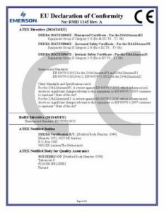
4 Declaration of Conformity
March 2021 Quick Start Guide
Quick Start Guide 13
Quick Start Guide March 2021
March 2021 Quick Start Guide
Quick Start Guide 15
![]()
Quick Start Guide00825-0600-2654, Rev. ADMarch 2021
©2021 Emerson. All rights reserved.
Emerson Terms and Conditions of Sale are available upon request. The Emerson logo is a trademark and service mark of Emerson Electric Co. Rosemount is a mark of one of the Emerson family of companies. All other marks are the property of their respective owners.
ROSEMOUNT ![]()
EMERSON Rosemount Sensor User Guide – EMERSON Rosemount Sensor User Guide –
References
[xyz-ips snippet=”download-snippet”]