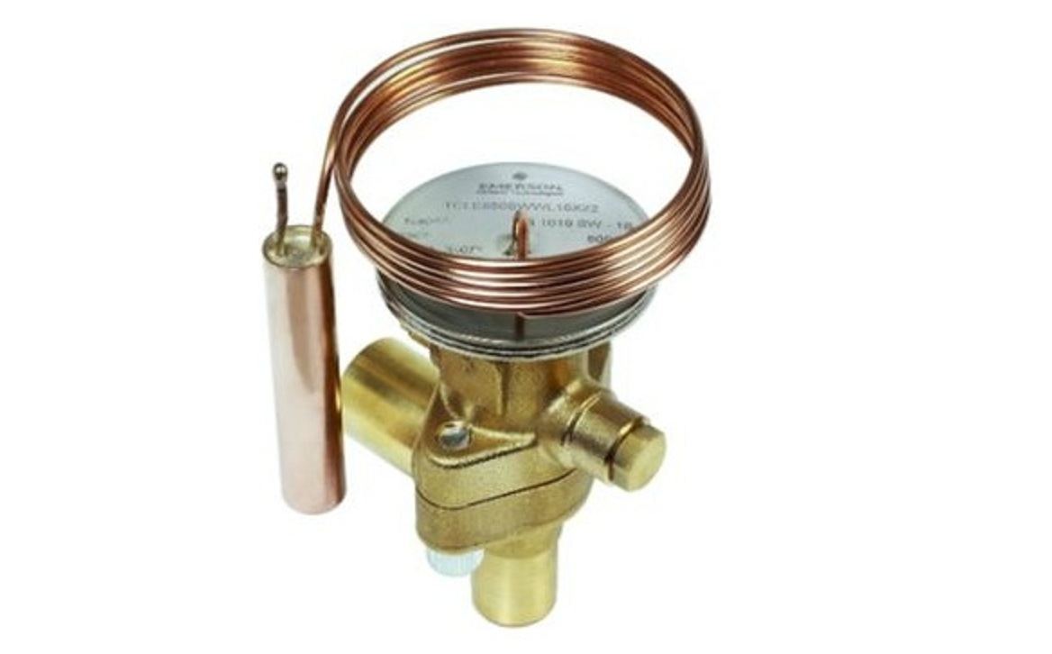
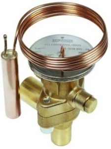
EMERSON Thermo Expansion Valve Series TIH Instruction Manual
General information:
TIH series of ThermoTM-Expansion Valves are designed for air conditioning, heat pumps and commercial refrigeration applications. The TIH is ideal for those applications requiring hermetic/ compact size combined with stable and accurate control over wide load and evaporating temperature ranges.
Safety instructions:
- Read operating instructions thoroughly. Failure to comply can result in device failure, system damage or personal injury.
- According to EN 13313 it is intended for use by persons having the appropriate knowledge and skill.
- Before opening any system make sure pressure in system is brought to and remains at atmospheric pressure.
- Do not release any refrigerant into the atmosphere!
- Do not exceed the specified maximum ratings for pressure and temperature.
- Do not use any other fluid media without prior approval of EMERSON. Use of fluids not listed could result in: Change of hazard category of product and consequently change of conformity assessment requirement for product in accordance with European pressure equipment directive 14/68/EU.
- Ensure that design, installation and operation are according to European and national standards/regulations.
Mounting location:
- Valves may be installed in any position, but should be located as close as possible to the distributor or evaporator inlet.
- Fig. 1 shows Heat pump application. Brazing: (Fig. 2)
- Perform and consider the brazing joint as per EN 14324
- Before and after brazing clean tubing and brazing joints.
- To avoid oxidization, it is advised to purge the system with an inert gas such as nitrogen while brazing.
- Do not exceed the max. body temperature of 120 C!
Installation:
![]() Warning:Do not bend capillary tube at interface to head of valve. Allowed: distance N (10 mm) and radius R (5 mm).
Warning:Do not bend capillary tube at interface to head of valve. Allowed: distance N (10 mm) and radius R (5 mm).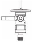
 Fig. 3
- Securely fasten the bulb with straps provided. Insulate bulb with a suitable material. The location of bulb on suction line is dependent to size of suction line (see Fig. 4)
- Be sure that the external equalizer line cannot siphon oil from the suction line.
- The expansion valve must be protected against all contaminants. Install a filter drier before the valve.
- Install a sight glass before the valve.
Pressure Test:
After completion of installation, a pressure test must be carried out as follows:
- according to EN 378 for systems which must comply with European pressure equipment directive14/68/EU.
- to maximum working pressure of system for other applications.
![]() Warning:
Warning:
- Failure to do so could result in loss of refrigerant and personal injury.
- The pressure test must be conducted by skilled persons with due respect regarding the danger related to pressure.
Leakage Test: Conduct a tightness test according to EN 378-2 with appropriate equipment and method to identify leakages of external joints.
Operation: Check for leaks, sufficient refrigerant charge and be sure no flash gas is present before attempting to check valve operation.
Proper operation of charges: The maximum bulb temperature is limited to:
| Charge Code | Charge | Max. bulb Temperature |
| Z1/Z3, M1/M3, N1/N3, C1/C3 | MOP | +120°C |
| M0/M2, C0/C2 | liquid | +100°C |
| N0/N2, B0/B2 | liquid | +80°C |
![]() Warning:Valves with gas charge feature MOP function and operate properly only if the temperature at the bulb is below the temperature at the head of the valve and at the capillary tube (see Fig. 5). If valve head becomes colder than the bulb, malfunction of the expansion valve occurs (i.e. erratic low pressure or excessive superheat).
Warning:Valves with gas charge feature MOP function and operate properly only if the temperature at the bulb is below the temperature at the head of the valve and at the capillary tube (see Fig. 5). If valve head becomes colder than the bulb, malfunction of the expansion valve occurs (i.e. erratic low pressure or excessive superheat).
Factory settings:
The table below provides the factory setting position of superheat adjusting stem and shows the number of turns clockwise when adjusting stem fully open counterclockwise
| Charge Code | Number of turns (360°) | Charge Code | Number of turns (360°) |
| Z1/Z3 | +5.5 | – | – |
| M1/M3 | +2.5 | M0/M2 | +2.5 |
| N1/N3 | +5.5 | N0/N2 | +4.5 |
| – | – | N0/N2 | +3.5 |
| C1/C3 | +1.5 | C0/C2 | +3 |
TIH in systems with nonstandard refrigerants: The following refrigerants can be used with standard available charges when factory setting to be readjusted for optimum superheat level. The readjustment depends to operating evaporating temperature and it is as guideline as follows:
|
Refrigerant |
Charge code | Evaporating temperature (°C) | ||||
| +5 | 0 | -10 | -20 | -30 | ||
| Number of turns | ||||||
| R32 | Z1 | -1 | 0 | 0 | 0 | – |
| R452B | Z1 | +2.5 | +2.5 | +2.5 | +2.5 | – |
| R454B | Z1 | +3 | +3 | +3 | +3 | – |
| R450A | M0 | +2.5 | +2 | +1 | +0.5 | – |
| R454C | N1 | 0 | 0 | 0 | 0 | – |
| R454C | N0 | +0.5 | +0.5 | 0 | -0.5 | – |
| R1234YF | C1 | 0 | 0 | 0 | +0.5 | – |
| R1234YF | C0 | 0 | 0 | 0 | +1 | – |
| R454A | B0 | -2 | -2 | -1 | -0.5 | 0 |
| R455A | B0 | +1.5 | +1.5 | +1.5 | +1.5 | +1.5 |
Note: Change of static superheat will shift MOP point in reverse direction.
Note2: TIH for R134a with MOP (M1) shall not be used for R450A.
![]() Warning :There are max. 12 turns on the adjustment stem (from left stop to right stop). When stop is reached, any further turning will damage the valve.
Warning :There are max. 12 turns on the adjustment stem (from left stop to right stop). When stop is reached, any further turning will damage the valve.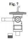

Note: + = Clockwise rotation – = Counterclockwise rotation
Superheat Adjustment:
If the superheat must be adjusted for the application proceeds as follows:
- Remove seal cap from bottom of valve.
- Turn the adjustment screw clockwise to increase the superheat and counterclockwise to decrease superheat. Changes in Superheat (K) per stem turn depending on evaporating temperature and refrigerant: Refrigerant
Refrigerant Evaporating temperature (°C) -30 -20 -10 0 +5 R410A 1.3C 1.0 0.8 0.6 0.5 R32 1.3 1.0 0.7 0.6 0.5 R452B 1.4 1.1 0.8 0.6 0.6 R454B 1.5 1.1 0.8 0.6 0.6 R407C 2.3 1.6 1.2 0.9 0.8 R448A 2.0 1.5 1.1 0.9 0.8 R449A 2.0 1.5 1.1 0.9 0.8 R134a – 2.5 1.8 1.4 1.2 R513A – 2.3 1.7 1.3 1.2 As much as 15 minutes are required for the system to stabilize after the adjustment is made.
- Determine superheat “sh” according to Fig. 6.
- Replace and tighten seal cap (hand tight).
Service / Maintenance: Defective TIH must be replaced, they cannot be repaired.
Technical Data:
| Max. working pressure PS | 46 bar |
| Factory test pressure PT | 50.6 bar |
| Medium temperature TS | -40…+70°C |
| Dimensions | Fig. 8 |
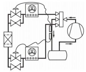 Fig.1
Fig.1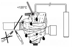 Fig. 2
 < 7/8” (28 mm/мм) ≥ 7/8“ (28 mm/мм)Fig.4
 Fig. 5
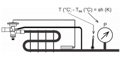 Fig. 6
Dimensions
 Fig.8
Fig.8
|
Type |
ODF (mm/мм)/ (inch/дюйм) | (mm/мм) | ||||||||||
| A | B | C | D | E | F | G | H | J | K | L | M | |
| TIH-…2 | 6 / 1/4″ | 10 / 3/8″ | internal | – | – |
70.7 |
8.4 |
8.4 |
10.3 |
87.5 |
73 |
45 |
| TIH-..3 | ||||||||||||
| TIH-..2 | 6 / 1/4″ | 10 / 3/8″ | 6 / 1/4″ | 43.5 | 8.4 | |||||||
| TIH-..3 | ||||||||||||
| TIH-..4 | 10 / 3/8″ | 12 / 1/2″ | internal | – | – |
68.7 |
10.4 |
8.4 |
||||
| TIH-..4 |
10 / 3/8″ |
12 / 1/2″ |
6 / 1/4″ |
43.5 |
8.4 |
|||||||
| TIH-..5 | ||||||||||||
| TIH-..6 | ||||||||||||
| TIH-..7 |
12 / 1/2″ |
16 / 5/8″ |
6 / 1/4″ |
64 |
13.1 |
10.4 |
||||||
| TIH-..8 | ||||||||||||
| TIH-..9 | ||||||||||||
| TIH-..A |
| Charge | (mm/мм) | |||
| N | R | Ø S | T | |
| M0/M2, N0/N2, B0/B2, C0/C2 | 10 | 5 | 15.9 | 53 |
| M1/M3, N1/N3, Z1/Z3, C1/C3 | 10 | 5 | 12.6 | 53 |
son Climate Technologies GmbH www.emersonclimate.euAm Borsigturm 31 I 13507 Berlin I Germany
References
[xyz-ips snippet=”download-snippet”]