
EMERSON™ 47D01U-843 Installation Instructions
Universal Heat Pump Defrost Control

![]()
Do not use on circuits exceeding specified voltage. Higher voltage will damage control and could cause shock or fire hazard. Route and secure wiring away from flame.
Protect the control from direct contact with water. If the control has been in direct contact with water, replace the control.
![]()
To prevent electrical shock and/or equipment damage, disconnect electrical power to system, at main fuse or circuit breaker box, until installation is complete.
Failure to read and follow all instructions carefully before installing or operating this control could cause personal injury and/or property damage.
The 47D01U-843 a universal replacement defrost control for single stage heat pump systems. The control is configurable for both demand, and time/temp defrost routines.
It is equipped with:
- 8 X 8 LED matrix display for set-up, operation and system troubleshooting
- Quick set-up menu by compressor brand.
- Outdoor thermostat functions to lock out compressor and / or aux. heat (optional)
- Short cycle and random start delays (optional)
- 24V brownout protection (optional)
PRECAUTIONS
- Installation should be done by a qualified heating and air conditioning contractor or licensed electrician.
- Do not exceed the specification ratings.
- All wiring must conform to local and national electrical codes and ordinances.
- This control is a precision instrument and should be handled carefully.
- Rough handling or distorting components could cause the control to malfunction.
- Follow installation/replacement instructions to ensure proper operation.
- The 47D01U-843 has no user serviceable parts. Replace as a unit.
SPECIFICATIONS
| Electrical Rating: | |
| Input Voltage | 24 VAC (Nominal) 50/60 Hz |
| Max. Input Current: | |
| Contactor Coil | 24 VAC (Nominal) 50/60 Hz |
| Aux Heat | 24 VAC (Nominal) 50/60 Hz |
| Reversing Valve | 24 VAC (Nominal) 50/60 Hz |
| Outdoor Fan | 1/2 HP @ 240V |
| Operating Temperature Range | -40° to +150° F (-40° to +65° C) |
| Humidity Range | 0 to 95% RH, Non-Condensing |
| Mounting | Multi-Position Surface Mount |
| Timing Specs | +/- 5% nominal over full voltage / temperature range.Timings 20% longer at 50Hz |
INSTALLATION
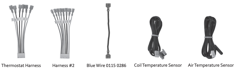
| 47D01U-843 Contents | Description |
| 47D01U-843 Control | Universal defrost control with plastic mounting tray |
| Thermostat Harness | Harness used to connect thermostat wires to control |
| Harness #2 | Harness used to connect reversing valve, contactor, low and high pressure switches |
| Blue Wire 0115 0286 | Goodman CC contactor common (if needed) |
| Sensors | Used to measure coil temperature and air temperature |
| Bag of Accessories | 2- Mounting screws, wire ties, wire nuts and labels. |
WIRING
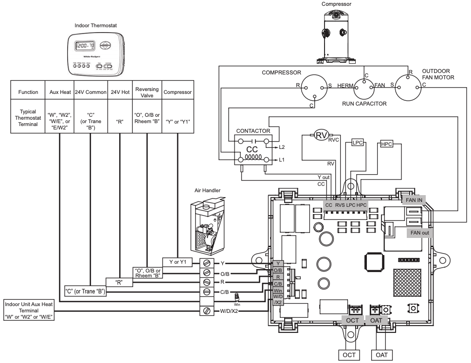
Refer to equipment manufacturer’s instructions for specific system wiring information. Wiring tables shown are for typical systems and describe the standard functions.
Diagram 1: OEM Wiring Diagram
WIRING TABLE

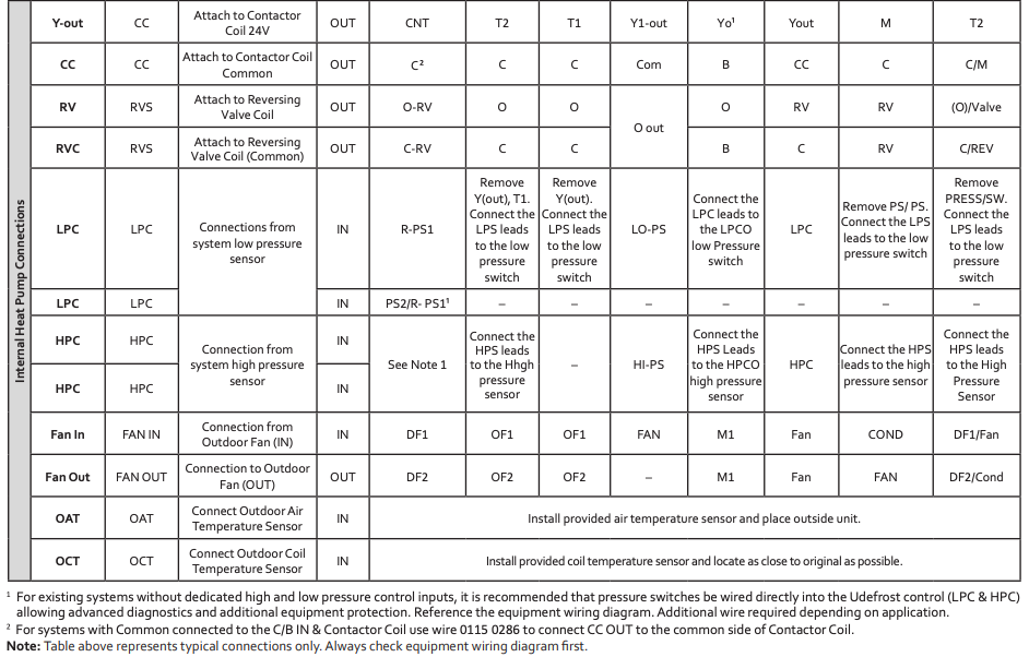
Note: Existing OAT and OCT sensor must be replaced.
Mounting (Reference Wiring Table)
- Disconnect power to unit
- Label wires (Reference OEM wiring diagram)
- Take a picture of the current installation
- Remove existing control
- Remove wires from control
- Position the new control and secure with provided mounting screws in desired location
- Connect labeled thermostat wires to thermostat harness and connect to the control
- Connect remaining labeled wires to harness #2 and connect to the control
- Connect outdoor coil temperature sensor
- Connect outdoor air temperature sensor
- Connect high pressure switch
- Connect low pressure switch
High/Low pressure switches are default enabled. Refer to table 2.
SETUP
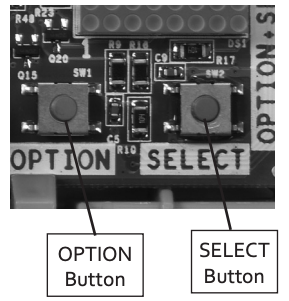
The 47D01U-842 control utilizes an 8×8 matrix display and two push buttons (OPTION) and (SELECT) to provide the user an easy and efficient way to setup the control.
OEM Quick Set-Up
- Turn the thermostat “Off” or disconnect the “Y” lead at the control to cancel any thermostat call for heat or cool.
- Turn on power, LED will display (all segments) followed by standby (
 )
) - Press the OPTION button for 1 second, control will display (do). Press SELECT until the characters are in an easy to read position (HI).
- Locate the Display number for the OEM equipment brand in the table below.
- Press OPTION 3 more times or until (oE) is displayed. Press SELECT until the control Display is set to the OEM number.
- Press OPTION again to confirm the setting – the control will display (Oe).
- Press OPTION (Repeatedly) until standby () appears or wait 30 seconds for the control to return to standby ()This configures the control to the standard OEM settings*.*Note: Individual set-up items can be customized using the full set-up table on the following page.
- Run the Forced Defrost – Quick Test below.
Forced Defrost – Quick Test Mode
This test provides a fast defrost cycle (about 30 seconds) to verify everything is connected correctly.
- Set the thermostat to call for Heat (Heat Pump) and verify the “Y” connection is attached to the control.
- The control will display “H” (Heating). Note: If the control blinks “H” the compressor time delay is active. To bypass the delay Press Option and Select for 1 second (control will briefly display (T)) or wait for the delay to time out.
- With the heat pump running (control displays “H”) Press Option and Select for 1 second. Control will display “T” (Test Mode) followed by “D” (Defrost).
- The reversing valve will change direction
- Aux Heat will energize
- Outdoor fan will turn off
- The Defrost test will end, control will display (H) (Heating).
The control is now ready for normal operation.
Note: If the control blinks “H” the compressor time delay is active. Press OPTION and SELECT for 1 second (control will briefly display (T)) to bypass the delay or wait for the delay to time out.
Note: If the control blinks “C” the compressor time delay is active. Press OPTION and SELECT for 1 second (control will briefly display (T)) to bypass the delay or wait for the delay to time out.
High/Low pressure switches are default enabled. Refer to table 2.
Table 1: OEM Quick Setup Options
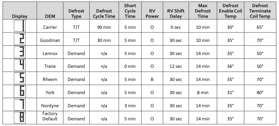
For additional setup options refer to Table 2
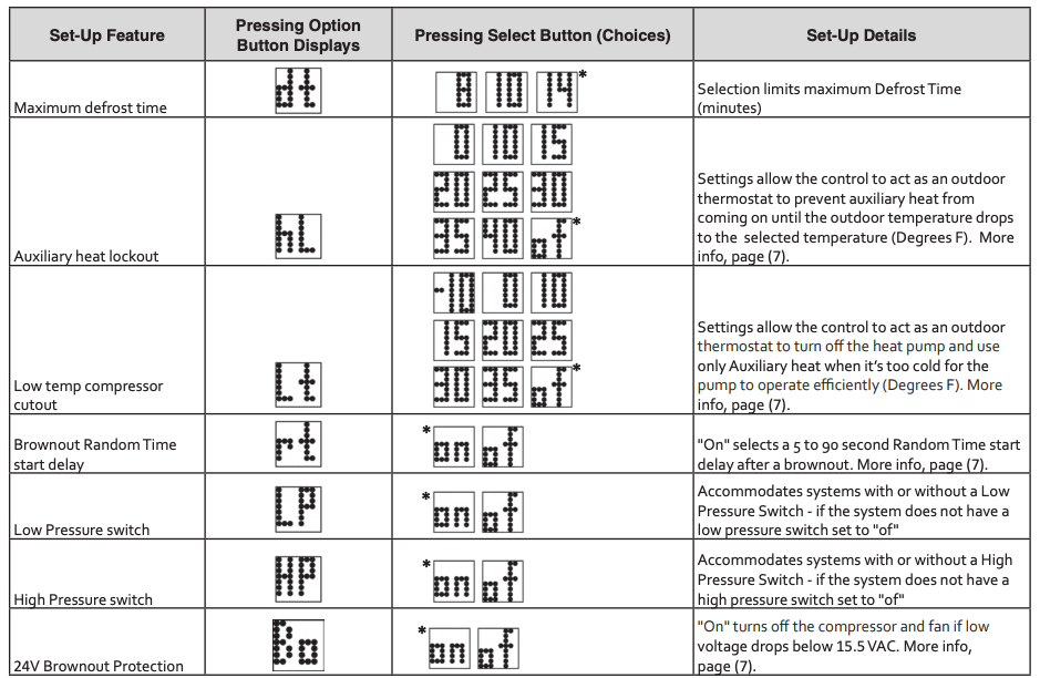
Table 2: Setup Table Options
To customize Set-Up options press the OPTION button to advance through the table.
To change a setting press SELECT. To confirm the choice press Option again.
When finished with Set-Up options press Option until (![]() ) appears or wait 30 seconds for the control to time out.
) appears or wait 30 seconds for the control to time out.

* Denotes Default Setting
Note: Options time out after 30 seconds
OPERATION
Demand Defrost Mode
Configured for demand defrost the controller monitors the mode of operation through the “B/O” terminal, outdoor temperature, outdoor coil temperature and compressor run time to determine when a defrost cycle is required.
- Defrost is initiated by calculating the difference between the outdoor temperature and coil temperature.
- At initial power up, a sacrificial defrost cycle initiates to make sure residual frost/ice has not accumulated on the coil before the control can calibrate itself.
Timed/Temperature Defrost Mode
Configured for Timed/Temperature defrost the control uses the outdoor temperature sensor, the defrost enable temperature and the defrost cycle time to initiate a defrost cycle.
- Compressor run time is accumulated when the coil temperature is below the defrost enable temperature (ET).
- If the compressor run time accumulated reaches the defrost cycle time, the control will enter defrost mode (dc).
Defrost Sequence for both Demand and Time/Temperature Modes
a.) Energize the auxiliary heat signal “W/D/X2” (out)b.) Switch the RV to cool mode and initiate Defrost Compressor Switching Delayc.) De-energize the compressor after “Defrost Compressor Switching Delay” time and initiate RV Shift Delay if RV Shift Delay selected is not zero. The system will not de-energize the compressor if the RV Shift Delay selected is zero.d.) De-energize the FAN.e.) The system will wait for the RV Shift Delay to expire if the RV Shift Delay selected is not zero.f.) Energize the compressor to start the Defrost operation, ignoring the Compressor Short Cycle Delayg.) Defrost is terminated when the coil temperature exceeds the selected termination temperature, or by maximum defrost time.
Short Cycle Time
At power-up as well as any time the compressor is de-energized, the control will activate a short cycle delay. During this delay the compressor will not be energized, even if a call for compressor operation is present. This is to prevent compressor damage due to rapid on and off cycling. Normal operation will resume when the delay expires.
Default Short cycle setting (SS) is at least 5 minutes. Selecting a shorter time could potentially shorten the life of the equipment.
Reversing Valve Shift Delay
This feature is used to limit potential noise issues on some compressors whenever the unit switches the reversing valve going in/out of the defrost cycle.
The reversing valve Shift Delay (Sd) is defaulted at 30 seconds.
Integrated Outdoor Thermostat Functionality (Optional). Aux Heat Lockout/Low Temp. Compressor Cutout.
Referencing Wiring Table (page 3)
Allows selection of an auxiliary heat cutout temperature (Aux Heat Lockout temperature). A user selectable low temperature cutout setting for the compressor can also be selected to prevent the compressor from operating below desired temperatures.
- Connection must be made from the indoor thermostat AUX to the Win located on the 47D01U-843 board.
- Select an Aux lockout temperature from the menu (hL).
- Select compressor lockout temperature from the menu (Lt).
Brownout Random Time Start Delay
At power-up and when the 47D101U-843 recovers from a brownout, a random time start delay of 5-90 seconds will be activated. This delay is in addition to the short cycle delay. During this delay the compressor will not be energized, even if a call for compressor operation is present. The random start delay can help reduce spikes in power consumption when multiple loads are re-energized after a blackout or brownout. The random time start delay is only active at initial power-up when recovering from a brownout. Normal compressor cycling will not activate the random start delay.
Random Time Start Delay (Rt) can be disabled by setting to the OFF position.
Brownout Protection
Brownout protection will de-energize the compressor and fan if the control voltage drops below 15.5V for more than 4 seconds during a call for compressor operation. Compressor operation will not resume until the control voltage returns to a minimum of 17.5V.
Brownout protection (Bo) can be disabled by setting to the off position (of).
TROUBLESHOOTING
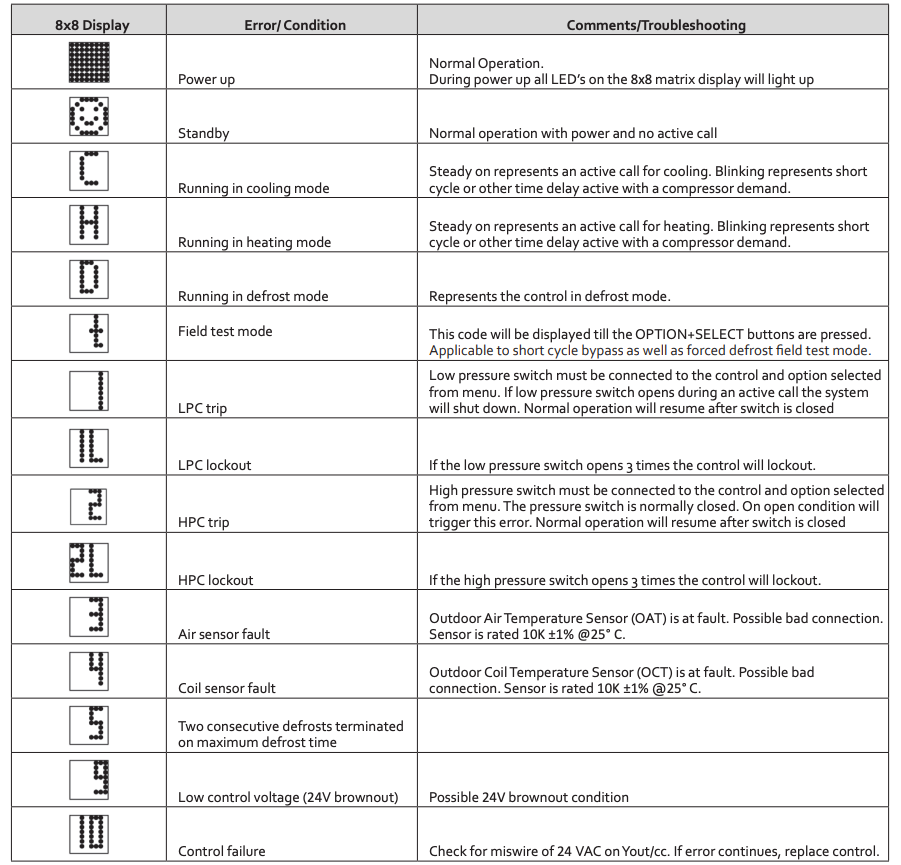
Active Error
Active errors are fault conditions present in the system. The highest priority error will show toggling between the operating condition followed by a 1 second pause. Any remaining active errors are displayed in the “Er” Error Menu. Once the condition is corrected, the errors will be removed from active status.
Fault Recall
Stored errors are fault conditions that can be recalled in the “Fr” menu. The last four faults will be stored with a maximum of two identical faults. Holding the OPTION+SELECT switch for greater than 7 seconds and less then 10 seconds will clear all fault(s). The display will flash “_” and “_” three times to indicate the fault(s) are successfully removed.
Table 3: Troubleshooting
TECHNICAL SUPPORT: 1-888-725-9797
Emerson and White-Rodgers are trademarks of Emerson Electric Co. ©2019 Emerson Electric Co. All rights reserved.
emerson.com/white-rodgers
References
[xyz-ips snippet=”download-snippet”]