
Emerson Wireless Module System and E2Quick Setup Guide
For a copy of the full Wireless User Manual (P/N 026-1734), go to https://climate.emerson.com to download it or contact Emerson Electronics and Solutions Technical Support at 833-409-7505.Emerson’s Wireless Module System allows quick and easy monitoring for a variety of Refrigeration and HVAC applications by connecting temperature probes, product simulators, humidity probes, or switches to the Wireless Module that transmits these signals to the Wireless Gateway. The Gateway translates the signal into usable information to send to the building controller, E2 (version 4.08 or higher) or Supervisory controller, where the data can be logged into reports or used by algorithms to make control decisions. The Wireless Gateway can receive signals from up to 99 Modules. The Wireless Module is flexible and configurable with up to three (3) analog or digital inputs that can be used for a variety of applications in Refrigeration and HVAC, eliminating installation materials and costly labor-intensive wiring.
Installing the Wireless Module

Figure 1 – Wireless Module Board Inside Enclosure
If this is a User Selected Input Module (P/N 814-3600), you must set the DIP switch setting based on the input being received from the sensor; either 0 to 5V or NTC/Digital.
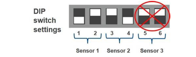
814-3600 User selectable model:• Set only one switch ON for each sensor pair• Each pair can be set separately
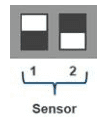 |
0-5V Input:• Humidity Sensor or Analog 0-5V Input• Pin 1 ON• Pin 2 OFF |
 |
NTC/Dig Input:• Temp or Digital Sensor Input• Pin 1 OFF• Pin 2 ON |
Table 1 – DIP Switch Settings
Setup and Commissioning of Module in E2
The Wireless Module must be associated with the Gateway through the Commissioning process. With proper range planning, all Modules can be commissioned to the Gateway prior to mounting. For complete instructions on the setup and commissioning of the Wireless Module, refer to the Wireless User Manual (P/N 026-1734).Steps to set up and commission the Wireless Module in E2:1. Go to the Add Application screen to add required number of RF Modules (Menu, 6, 1, F4: Lookup, 23. RF Module) then press Enter.2. Enter how many (99 max per Gateway) and press Enter.3. Once the RF Module application has been added, go to Configured Applications to commission the device (Menu, 5, 230. RF Module).4. Select an RF Module from the list and press Enter.5. Pull up the Actions Menu, and initiate commissioning (Enter, 9, 1: Commission Device).6. The application will enter learning mode.7. Within one (1) minute, press the Learn button on the Module.
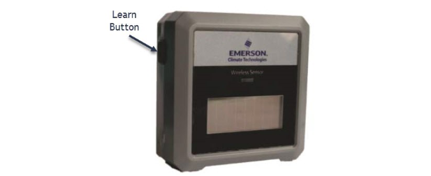
Figure 2 – Wireless Module Enclosure
Document Part # 026-4255 Rev 3©2021 Emerson Climate Technologies Retail Solutions, Inc. This document may be photocopied for personal use. Visit our website at http://www.climate.emerson.com for the latest technical documentation and updates.
![]()
During the commissioning process, press the Learn button and the following occurs:Blue LED:• 1 blink = learning/commissioning started.• 2 blinks = commissioning was successful (occurs in one (1) second).8. If successful, the Module Status will display Commissioned, then Good on the E2. Check signal strength prior to mounting the Modules permanently. If reception levels are not sufficient, repositioning or use of repeaters may be necessary.
Check Signal Reception
1. Go to the RF Module main screen (Menu, 5, 230. RF Module), select the Module then press Enter.2. From the Actions menu, select Application Logs/Graphs (Enter, 8. Application Logs/Graphs).3. Select 1. Module Stats and press Enter.The Application Log screen will show the SSI Signal Strength.The lower the negative number, the higher the signal strength.
| 4 Bars | >= -75 | VERY GOODReception rates > 98% |
| 3 Bars | <-75 and >=-85 | GOODReception rates > 95% |
| 2 Bars | <-85 and >=-90 | FAIRReception rates < 95% |
| 1 Bar | <-90 and >= -95 | POORReception rates <70% |
| 0 Bars | <-95 | FAILReception rates <50%OPEN Module alarms |
Table 2 – SSI Signal Strength Values
Wireless Module System Parts and Accessories
| Part Number | RF Description |
| 814-3550 | Wireless Gateway 902MHz |
| 814-3560 | Wireless Repeater 902MHz, 24VAC |
| 814-3570 | Wireless Repeater 902MHz, 120VAC |
| 501-1121 | Temp Sensor, General Purpose |
| 508-9101 | Temp Sensor, Product Simulator |
| 201-1160 | Temp Sensor, NSF |
| 140-6801 | Optional wall-mount 5V power supply |
Table 3 – Ordering Information
Document Part # 026-4255 Rev 3
Module Commissioning Tips
- Hours on battery is displayed in the Module Summary screen. The battery will last for 17,100 hours of use. The battery is still good if the voltage is 2.90 or higher.
- It takes 200 lux five (5) hours per day to run the RF Module on the solar cell continuously.
- Place Modules so that the solar cell can power the Module and battery usage indicator remains Off.
- The default update rate of two (2) minutes optimizes power consumption.
- Faster update rates may require an external 5V power supply (available as an option).
- With proper range planning, all Modules can be commissioned to the Gateway with the Learn button prior to mounting.
- Check signal strength on the E2 prior to mounting the Modules permanently.
- Use the Test button for instant transmission if you do not want to wait for the regular update rate.
- Placement of the Modules should be positioned so that SSI reception levels are 3 or 4 Bars. Reposition or use repeaters as necessary.
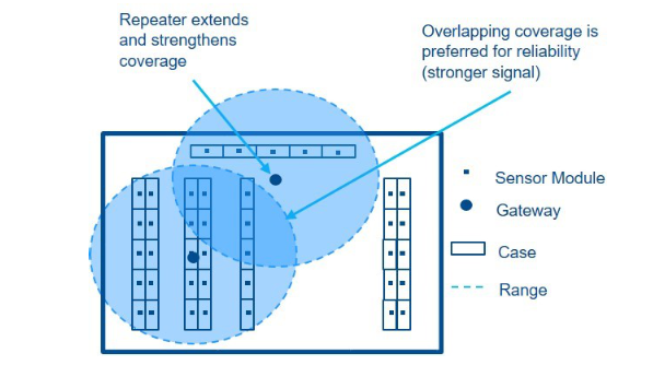
Figure 3 – Overlapping Coverage Area
For a copy of the full Wireless User Manual, scan the QR Code:
 [PDF]
[PDF]
This document may be photocopied for personal use.Visit our website at http://www.climate.emerson.com for the latest technical documentation and updates.Join Emerson Technical Support on Facebook. http://on.fb.me/WUQRntFor Technical Support call 833-409-7505 or email ColdChain.[email protected]The contents of this publication are presented for informational purposes only and they are not to be construed as warranties or guarantees, express or implied, regarding the products or services described herein or their use or applicability. Emerson Climate Technologies Retail Solutions, Inc. and/or its affiliates (collectively “Emerson”), reserves the right to modify the designs or specifications of such products at any time without notice.Emerson does not assume responsibility for the selection, use, or maintenance of any product. Responsibility for proper selection, use, and maintenance of any product remains solely with the purchaser and end-user.
References
[xyz-ips snippet=”download-snippet”]