
White-Rodgers Carrier Integrated Single Stage 120V Hot Surface Ignition Control Kit 50M56D-751INSTALLATION INSTRUCTIONS
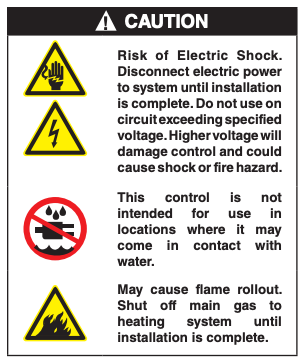
FAILURE TO READ AND FOLLOW ALL INSTRUCTIONS CAREFULLY BEFORE INSTALLING OR OPERATING THIS CONTROL COULD CAUSE PERSONAL INJURY AND/OR PROPERTY DAMAGE.
PARTS INCLUDED
- 50M56D-751 Integrated Furnace Control
- 2 – 1/2″ Sheet Metal Screws
- Installation Instructions
DESCRIPTION
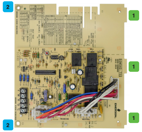
50M56D-751 is an aftermarket direct replacement control kit for Carrier single stage furnace products with PSC blower motors.
TWINNING: 50M56D-751 can be twinned. The other control must also be a 50M56D-751 to ensure proper functionality.
SPECIFICATIONS & TIMINGS
ELECTRICAL RATINGS:Input Low Voltage: 24 VAC, 60 HzInput Line Voltage: 120 VAC, 60 Hz, 1φMax Input Current: 0.45 A @ 24 VACRelay Contact Ratings:
Gas Valve: 1.5 A, 0.6 PF @ 24 VACIgnitor Relay: 1.2 A @ 120 VACInducer Relay: 2.8 A @ 120 VACCirculator Relay: 10 FLA, 25 LRA @ 120 VACHumidifier Load: 1.0 A @ 24 or 120 VACElectronic Air Cleaner: 1.0 A @ 120 VAC
Flame Current Requirements:
Minimum current to ensure flame detection: 0.25 μA DC*Maximum current for non-detection: 0.1 μA DCMaximum allowable leakage resistance: 100 M ohms* Measured with a DC ammeterFlame Establishing Time: 0.8 seconds maximumFlame Failure Response Time: 2.0 seconds maximum
OPERATING TEMPERATURE RANGE:
-40° to 176°F (-40° to 80°C)
HUMIDITY RANGE:
5 to 95% relative humidity (non-condensing)
AGENCY APPROVALS: UL USA / Canada
GASES APPROVED: Natural, Manufactured, Mixed, Liquid Petroleum, and LP Gas Air Mixtures.
WIRING
NOTE: All wiring should be installed according to local and national electrical codes and ordinances.
- Disconnect electrical power and shut off gas supply to unit, then remove unit access panels.
- Mark and disconnect all wires from the existing control, then remove existing control.
- Mount 50M56D-751 in the unit following the instructions in the Mounting section. Be certain not to damage any components such as wire harnesses or blower wheels when drilling or installing screws.
- Connect all the wires back onto the 50M56D-751 control board referencing the Wiring Diagram section as needed.
- Ensure all wires are secure to the control board and unused blower speed wires are attached to the PARK terminals. Apply wire ties as needed to secure wiring.
- Verify Inducer OFF / Heat ON delay, Constant Fan Speed, and Heat OFF Delay settings, as described in the Configuration section.
- Reinstall unit access panels and reconnect electric power. Restore gas supply to the unit. 8. Verify unit operation in heating, cooling, and fan only mode.
MOUNTING
- Slide tabs into slots in sheet metal mounting bracket.
- Align corner holes with sheet metal holes and secure with 2 ½” screws.
NOTE: Ensure a proper ground connection is made between the control and the chassis of the furnace. The bottom of the control board underneath screw locations should make solid contact with clean metal on the mounting bracket and be secured firmly with screws to ensure proper grounding and control operation.
Dipswitch Settings

*Default
NOTE:SW 1-1 selects both the inducer OFF delay and heat ON delay simultaneously. For example, the default setting (switch ON) sets the inducer OFF delay to 5 seconds and the Heat ON delay for the blower to 45 seconds.
SELF TEST
Enter Self-Test immediately after control power up by:
- Double pressing the “FAULT RECALL” button while LED rapid flashes green.NOTE: Control will terminate Self-Test mode if any system fault occurs. Control will ignore any active thermostat calls during Self-Test.
- Sequence is as follows:
- LED will flash all stored fault codes five times. If there are no faults, the LED will be off for 2 seconds.
- Afterward, the LED will slowly flash code 11 in alternate colors (green, amber, red) to indicate Self-Test is active. This will continue until Self-Test is complete.
- Inducer motor will turn ON and continue running until Self-Test is complete.
- After 15 seconds, the ignitor will turn ON for 15 seconds, then OFF.
- Blower motor runs at the Fan (SW1-2), Heat, and Cool speeds respectively for 10 seconds each.
- Blower and Inducer motors turn OFF.
- Self-Test is complete, LED will display solid green to indicate Standby mode.
WIRING DIAGRAM

NOTE: The factory installed wiring harness on the 4, 12, and 16 pin connectors must remain in place for the control to function.
OPERATION
HEAT MODE
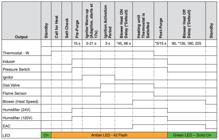
Fan
- The constant fan speed (G) is determined by the fan speed tap selected with dipswitch SW1-2 (LO/HEAT speed is default).
- There is a 1 second blower ON delay and a 1 second blower OFF delay for a fan only demand.
- Set thermostat to Fan ON for continuous fan.
Cool On / Off Delays
- Cool blower ON delay is 2 seconds.
- Cool blower OFF delay is 90 seconds.
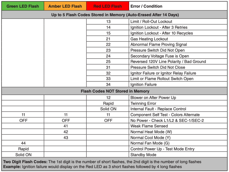
TROUBLESHOOTING
Fault Recall
When the control is in standby mode, press and hold the “FAULT RECALL” button for about 3-5 seconds until the solid green LED turns off, then release the button.
NOTE: While displaying the stored fault codes, the control will ignore any new call for heat, cool, or fan.
Fault Code Reset
When the control is in standby mode, press and hold the “FAULT RECALL” button until the diagnostic LED begins to rapid flash for about 7-10 seconds then release the button.
The LED will turn off for 2 seconds after fault codes are erased. Faults will automatically be cleared from memory after 14 days.
NOTE: If the switch is held pressed for over 10 seconds, faults will not be cleared, rapid flash will stop, and the LED will be solid green to indicate return to standby.
OPERATION
Control Reset
Control reset is automatic after 1 hour in lockout. Removing 24 VAC power to the control for greater than 10 seconds will manually reset the control.
Flame Current Test
Set multimeter to DC volts and place leads on the flame current sense pins. Read the voltage directly as microamps (1 VDC = 1µA) with the burners on.
Reading results: 0.5 – 1.0 = marginal, 1.0 – 5.0 = good.
TECHNICAL SUPPORT: 1-888-725-9797
White-Rodgers Carrier Integrated Single Stage 120V Hot Surface Ignition Control Kit 50M56D-751 User Manual – White-Rodgers Carrier Integrated Single Stage 120V Hot Surface Ignition Control Kit 50M56D-751 User Manual –
[xyz-ips snippet=”download-snippet”]