
User Manual
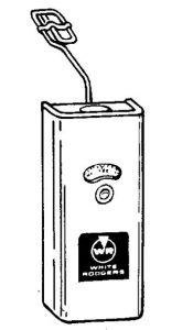
White-Rodgers Type 416-4 Warm Air SPDT Limit Control
FAILURE TO READ AND FOLLOW ALL INSTRUCTIONS CAREFULLY BEFORE INSTALLING OR OPERATING THIS CONTROL, COULD CAUSE PERSONAL INJURY AND/OR PROPERTY DAMAGE.
KEEP INSTRUCTION SHEET FOR FUTURE USE.This Warm Air Limit Control has single pole double throw switch action. It may be used as a limit control by using the open on rise terminals (Red-Blue). It may also be used as a fan control (if the 20 ° F. fixed differential is acceptable) by using the close on rise terminals (Red-White).
This control is also suitable for use as a “fan selector control” on 2-speed blower applications.
This control is suitable for use on 25 volt circuits as well as line voltage equipment such as gas valves, oil burner motors, etc.
SPECIFICATIONS
- Switch Action: Single Pole, Double Throw
- Range: 100 to 3500 F.
- Differential: Fixed 200 F.
- Element Length: 9″
A.C. Electrical Rating:
- Motor Load (Full Load): 7.4A at 120v.3.7A at 240v
- Non-Inductive: 7.4A at 120v.3.7 A at 240v.
- Valves & Relays: 4.4A at 25v.
SAFETY
THESE CONTROLS MUST BE INSTALLED BY A QUALIFIED INSTALLER.
Do not exceed the specification ratings.
All wiring must conform to local and national electrical codes and ordinances.
This control is a precision instrument, and should be handled carefully. Rough handling or distorting components could cause the control to malfunction.
CAUTION To prevent electrical shock and/or equipment damage, disconnect electric power to system, at main fuse or circuit breaker box, until installation is complete.
WARNING Do not use on circuits exceeding specified volt age. Higher voltage will damage control – could cause shock or fire hazard.
INSTALLATION
If this control is supplied as a part of a complete furnace assembly disregard the installation herein contained and follow the recommendations or instructions as supplied by the furnace manufacturer.
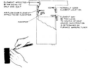
The control should be attached to the furnace casing in such a position that the thermal element will be located in the heated area which is subjected to the most rapid temperature changes. The proper position is usually near the top or the bonnet of the furnace. No barriers, such as baffles, ducts, or other obstructions, should be present to interfere with the free flow of air around the element. The element should be bent so that when the control is permanently installed it will not contact the heated surface or be affected by reflected, conducted, or radiated heat. This precaution is necessary to insure operation from the true air temperature. Care must be exercised when bending the element to prevent “kinking” it. The element should not be bent with a radius less than one inch and all bendings should be done between the coiled part of the element and a point one inch from the diaphragm cup.
DIAL SETTING
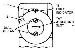
Insert screwdriver in slot “A” and turn dial until fixed indicator “B” points to temperature at which Red-Blue contacts are to open and Red-White contacts are to close. After fall in temperature of about 20° F., Red-Blue contacts will close and Red-White contacts will open.
Controls With Adjustable Stops
- Loosen stop screw “E” with enclosed wrench.
- Set dial to original equipment manufacturer’s specification.
- Without moving the dial, move stop tab “F” against indicator.
- Re-tighten stop screw “E”.
CAUTIONSetting stop higher than control being replaced could cause personal injury and/or property damage.
WIRING
All wiring should be done according to local and national electrical codes
This control has a single-pole, double-throw snap action switch. The top left-hand terminal (red) is the common terminal. The top right-hand terminal (blue) has open-on-rise switch action. The bottom center terminal (white) has close-on-rise switch action.
- To use as limit control, use Red-Blue contacts.
- To use as fan control, use Red-White contacts.
- To use as “fan selector control”, wire as in diagram below.
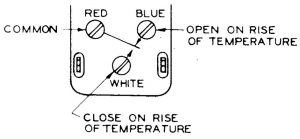
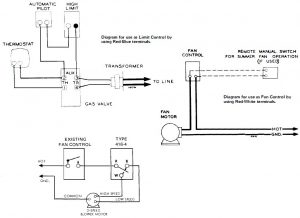
Diagram for use as “Fan Selector Control” by using all three terminals.
Existing fan control starts and stops blower. Type 416-4 determines speed at which blower runs, switches blower to high speed as R-W contacts close. On combination heating-cooling systems, wiring circuit must prevent high speed and low speed motor windings from being energized simultaneously.
White-Rodgers Type 416-4 Warm Air SPDT Limit Control User Manual – White-Rodgers Type 416-4 Warm Air SPDT Limit Control User Manual –
Questions about your Manual? Post in the comments!
[xyz-ips snippet=”download-snippet”]