White-Rodgers 50F06-843 Universal Furnace Electronic Fan Timer Control Kit
INSTALLATION INSTRUCTIONS
FAILURE TO READ AND FOLLOW ALL INSTRUCTIONS CAREFULLY BEFORE INSTALLING OR OPERATING THIS CONTROL COULD CAUSE PERSONAL INJURY AND/OR PROPERTY DAMAGE.
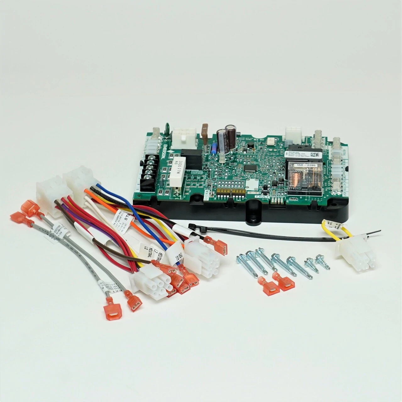
PARTS INCLUDED
- 50F06-843 Electronic Fan Timer Control Board
- 2 – Main Harness Assemblies (ST9101, ST9141)
- 1 – Jumper Harness (ST9160)
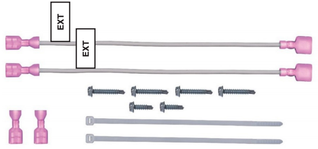
- 2 – 7” Long Transformer Wiring Extensions (EXT)
- 2 – 3/16” QC crimp on terminals for optional use with Wiring Extensions
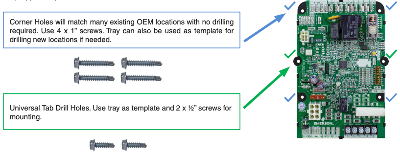
- 4 – 1” Sheet Metal Mounting Screws (for mounting tray corner locations)
- 2 – ½” Sheet Metal Mounting Screws (for mounting tray center tabs)
- 2 – Wire Ties
- Troubleshooting Label
- Installation Instructions
DESCRIPTION
The 50F06-843 is an aftermarket universal replacement fan timer control kit for single stage furnaces with PSC inducer and blower motors.
TWINNING: 50F06-843 can be twinned. Both control boards must be from the same manufacturer for proper functionality.
SPECIFICATIONS
ELECTRICAL RATINGS:
Input Low Voltage: 25 VAC, 60 HzInput Line Voltage: 115/230VAC, 60 Hz, 1φMax Input Current: 800mA @ 25 VACRelay Contact Ratings:
Inducer Output: 1.5 FLA @ 115 VAC .75A @ 230 VACBlower Output: 15 FLA @ 115 VAC 7.5A FLA @ 230VACHumidifier and EAC Load: .8A FLA @ 115 VAC.4A FLA @ 230VAC
POST PURGE TIMING: 5 secondsLOCKOUT AUTO RESET TIMING: 60 minutesOPERATING TEMPERATURE RANGE: -40° to 176°F (-40° to 80°C)HUMIDITY RANGE: 5 to 95% relative humidity (non-condensing)GASES APPROVED: Natural, Manufactured, Mixed, Liquid Petroleum, and LP Gas Air Mixtures.
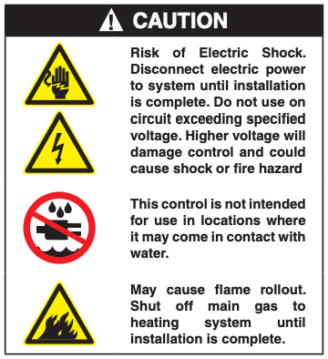
TABLE 1: CROSS REFERENCE, HARNESS SELECTION, DIPSWITCH SETTINGS
(Harness Part Numbers Match Control Model Being Replaced for Easy Identification)
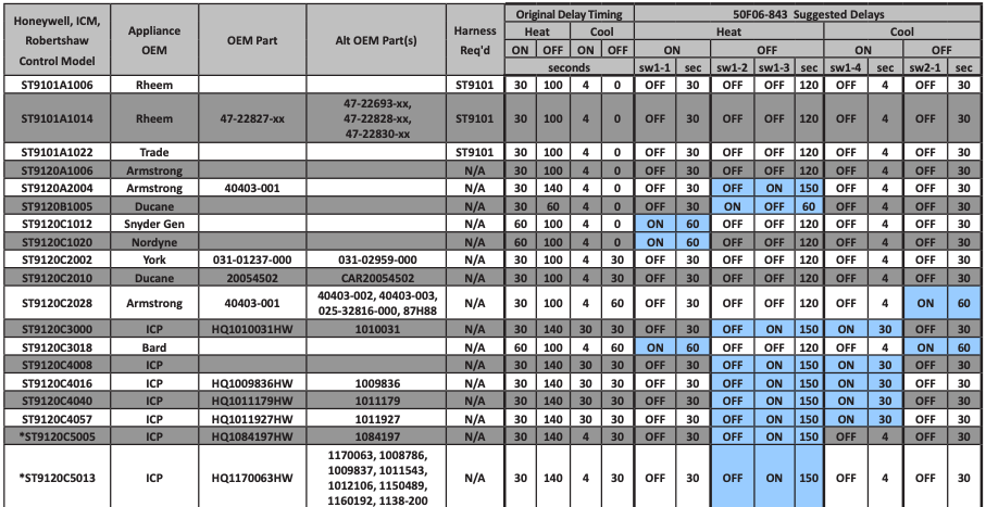
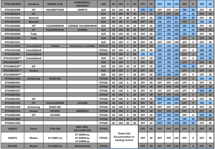
* Heat Fan Off Delay setting may need adjustment based on performance** Replacement requires 60Hz power supplyBLUE SHADING = A CHANGE FROM DEFAULT SELECTION IS REQURED
DIPSWITCH CONFIGURATION
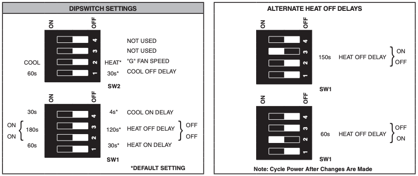
Notes:
- To change settings break through yellow protective plastic film and make required adjustments
- See Table 1 for dipswitch setting recommendations by control board part number (any changes to be made from 50F06-843 defaults will be highlighted in BLUE)
- Cycle power after making any changes
INSTALLATION ACCESSORIES
- 7” long wiring extensions EXT can be used if existing transformer wires do not easily reach the new control board connections. Extension wires have ¼” male x ¼” female spades
- 3/16” male crimp-on quick connects can be used to modify the EXT extension leads if they are needed for units having smaller transformer connections
- Mounting screws can be used with the plastic tray CORNER HOLES (4x long) or MOUNTING TABS (2x short)
- Wire ties can be used to secure any wiring as needed
- Troubleshooting label can be placed on furnace access panel for referencing dipswitch setup and LED codes
ADAPTER HARNESSES, JUMPER PLUG, AND WIRING NOTES
(Harness Part Numbers Match Control Model Being Replaced for Easy Identification)
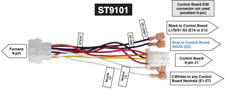
Used with Honeywell ST9101, ICM270, and Robertshaw 695-003 Control Replacements
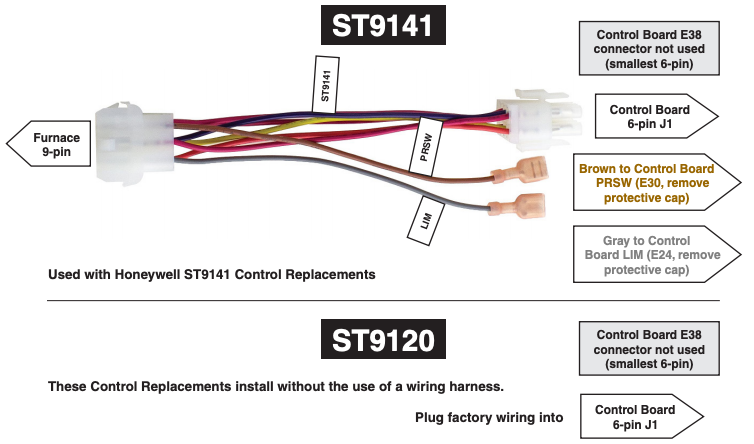
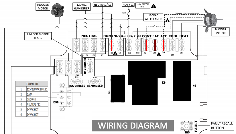
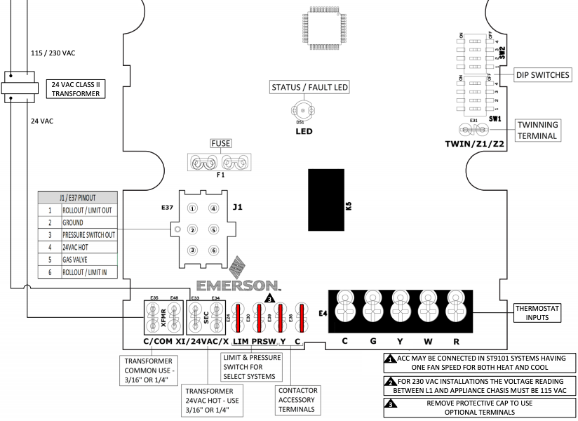
For additional details please see WIRING DIAGRAM and original appliance schematic
INSTALLATION
MOUNTING AND WIRING
NOTE: All wiring should be installed according to local and national electrical codes and ordinances.
- Disconnect electrical power and gas supply to unit, then remove unit access panels.
- Mark and disconnect all wires from the existing control, then remove control. TIP: first take a picture or two for reference.
- 50F06-843 can be mounted in any orientation. Select a location that will not damage, obstruct or place any stress on the terminations or harnesses.
- Mount 50F06-843 in the unit using one of the two mounting tray options noted below. Be certain not to damage any components such as transformers, wire harness or blower wheels when drilling or installing screws.
- Refer to Table 1 and select the proper wire adapter(s) or jumper needed to replace the existing control board (if applicable).
- Adjust Cool ON, Cool OFF, Heat ON, and Heat OFF delay dipswitches if needed per Table 1 and “Dipswitch Configuration” section.
- Reconnect all wires to 50F06 control board referencing “Adapter Harnesses, Jumper Plug, and Wiring Notes”, “Wiring Diagram”, and “Blower, Accessory, and System Operation” sections as needed.
- Ensure all wires are secure to the control board and unused blower speed wires are attached to the M1, M2, M3 / Unused terminals. Apply wire ties as needed to secure wiring.
- Install provided Troubleshooting Label in a suitable location for easy viewing.
- Reinstall unit access panels and reconnect electric power and gas supply to the unit. 11.Verify unit operation in Heat, Cool, and Fan modes.
Additional Notes:
- ST9101 systems (also ICM270/RS 695) have INDUCER MOTOR, HOT / L1, and NEUTRAL / L2 connected through adapter harness
- ST9141 systems have Limit and Pressure Switch connected through adapter harness to E24 (LIM) and E30 (PRSW) terminals
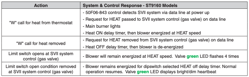
- ST9160 systems have INDUCER MOTOR connected to Gas Valve control
SELF-TEST
50F06-843 is equipped with a self-test routine that checks the functionality of the control, blower, and inducer to verify they are in proper working order. Ensure thermostat is turned OFF or thermostat wires are disconnected to enable.
ENTER SELF-TEST BY:
- Turn on power and/or manually close blower door switch
- Wait 1 second
- Slowly double-click “FAULT” button within ~3 seconds
SEQUENCE IS AS FOLLOWS:
- LED will flash in red the five last stored fault codes
- Afterward, the LED will slowly flash alternate colors (red, amber, green) to indicate Self-Test is active and continue until Self-Test is complete
- For ST9160 furnaces using E38 primary connector: 1. Blower operates HEAT speed for 10 seconds
- Blower operates HEAT speed for 10 secondsNOTE: Self-Test is available after power up and until a solid green LED is present (5 seconds after power up). During this time, the control will ignore all active calls. If a solid green LED is present, disconnect power for 10 seconds before starting Self-Test routine.
- Blower operates COOL speed for 10 seconds
- Blower shuts off and control goes to Standby
- For all ST9101, ST9120, and ST9141 Furnaces using J1 primary connector:
- Inducer operates for 7 seconds
- Blower operates HEAT speed for 10 seconds, inducer continues to run
- Blower operates COOL speed for 10 seconds, inducer is off
- Blower shuts off and control goes to Standby
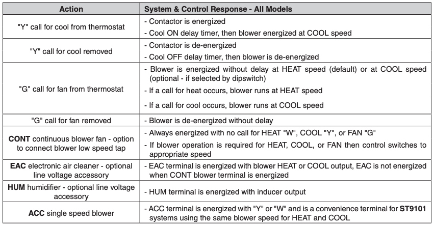
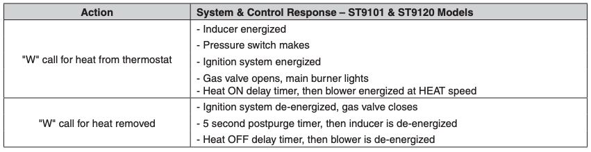
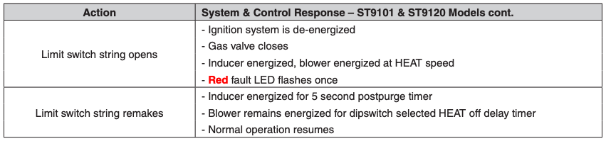
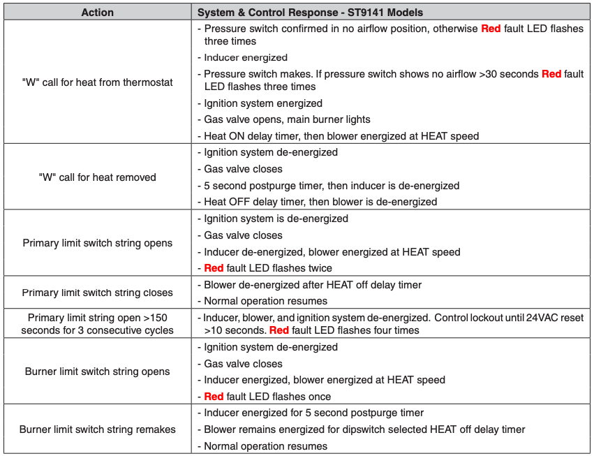
BLOWER, ACCESSORY, AND SYSTEM OPERATION DETAILS
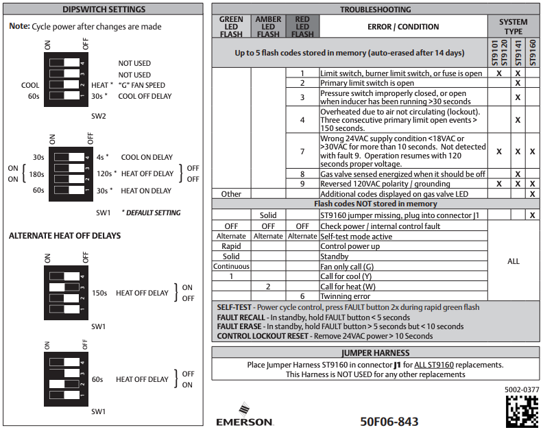
TROUBLESHOOTING, FAULT AND STATUS CODES
The LED will indicate fault or status codes as shown in the table below:

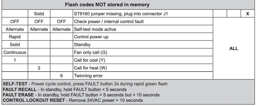
FAULT RECALL
When the control is in Standby mode (no call for heat or cool), press the fault button for approximately 2 to 5 seconds or until the diagnostic LED turns off. Up to 5 fault codes are stored.
NOTE: While displaying the stored fault codes, the control will ignore any new call for heat, cool or fan.
FAULT CODE ERASE & RESET
When the control is in Standby mode (no call for heat or cool), press the fault button for 5 to 10 seconds or until the diagnostic LED begins to rapid flash.
NOTE: If the button is pressed for over 10 seconds the rapid flash will stop and the control will return to Standby.
CONTROL LOCKOUT RESET
Control automatically resets after 1 hour in lockout. Removing 24VAC power to the control for greater than 10 seconds will reset the control.
TWINNING
- Connect Twin/Z1/Z2 terminal between two boards using an 18ga wire. Boards must be from same manufacturer.
- Board with thermostat connected has full functionality including LED and dipswitch settings. Twinned board will operate blower only simultaneously (LED showing Standby) unless “W” or “Y” are powered to it.
- Twinned unit can be wired for Heat by utilizing the “W” terminal either with the 1st unit or as a 2nd stage.
TECHNICAL SUPPORT: 1-888-725-9797
White-Rodgers Universal Furnace Electronic Fan Timer Control Kit 50F06-843 User Manual – White-Rodgers Universal Furnace Electronic Fan Timer Control Kit 50F06-843 User Manual –
[xyz-ips snippet=”download-snippet”]