enbrighten 46199 In-Wall Add-on Switch User Guide
Tools you will need
Overview
- A. Rocker paddle – the add-on switch takes the characteristics of the primary switch. Refer to the primary switch’s manual for instructions.
- CC. Ground (Green/Bare)
- DD. Traveler (Red/Other)
- BB. Neutral (White)
To change color of the paddle
This step is optional. Before installation, you may want to change the color of the paddle to match your wallplate or decor.
- Push side tabs in on one side and then the other to release paddle. Lift the cover up and off.
- Simply put the new paddle onto the switch by side tabs and snap securely into place
Once this step has been completed, please proceed to section 3.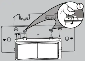
Standard 3-Way Switch
Enbrighten Switch
Insert wires into holes, do not wrap wires around screws.
Do not remove screws.

WARNING — SHOCK HAZARD
Turn OFF the power to the branch circuit for the switch and lighting fixture at the service panel. All wiring connections must be made with the POWER OFF to avoid personal injury and/or damage to the switch.
This device is intended for installation in accordance with the National Electric Code and local regulations in the United States or the Canadian Electrical Code and local regulations in Canada. If you are unsure or uncomfortable about performing this installation, consult a qualified electrician.
IMPORTANT
3-way switches can be wired in different ways. These instructions explain the most common method. If you have difficulty with the instructions or your home wiring, contact a licensed electrician for assistance.
- Shut off power to the circuit at circuit breaker or fuse box.IMPORTANT! Verify power is OFF to switch box before continuing.
- Remove both wallplates.
- Remove the switch mounting screws.
- Carefully remove the switch from each switch box location. DO NOT disconnect the wires yet.
- Identify switch connected to fuse box. This is the “line switch.” Label wire connected to common terminal “LINE.”
- Identify switch connected to lighting/fixture. This is the “load switch.” Label wire connected to common terminal “LOAD.”
Observe important wiring information
IMPORTANT: This add-on switch is rated for and intended to only be used with copper wire.
Wire gauge requirements
Use 14AWG or larger wires suitable for at least 80° C for supplying line (hot), load, neutral, ground and traveler connections.
Wire strip length
- For attachment using the enclosure’s holes, strip insulation 5/8in. (16mm). UL specifies the tightening torque for the screws is 14Kgf-cm (12lbf-in)
Switch connected to fuse box “line switch”(Replacing standard switch with Enbrighten primary switch).
- Disconnect all wires on existing switch.
- Locate neutral wires found inside switch box. These are typically a bundle of white wires in the back of the box. Remove wire nut securing them (A).
- Locate jumper wire included in packaging of primary switch. Connect with neutral wires and secure with wire nut (A).
- Connect opposite end of jumper wire to NEUTRAL terminal on primary switch (B).
- Connect wire labeled “LINE” to LINE terminal on primary switch (C).
- Connect ground wire (bare/copper/green) to GROUND terminal on primary switch (D).
- Connect one of the two remaining wires (T1) to LOAD terminal on primary switch (E). Write down the color of the wire. You will need this when installing the add-on switch.
- Connect the remaining wire (T2) to TRAVELER terminal on the primary switch (F).
Switch connected to lighting “load switch”(Replacing standard switch with Enbrighten add-on switch)
- Disconnect all wires on existing switch.
- Locate neutral wires found inside switch box. These are typically a bundle of white wires in the back of the box. Remove wire nut securing them (AA).
- Locate jumper wire included in packaging of primary add-on switch. Connect with neutral wires and secure with wire nut (AA).
- Connect opposite end of jumper wire to NEUTRAL terminal on add-on switch (BB).
- Connect ground wire (bare/copper/green) to GROUND terminal on add-on switch (CC).
- Locate the same colored wire you noted in the switch box (T1). Using a wire nut, secure it only to the wire you labeled “LOAD.”
- Connect the remaining wire to TRAVELER terminal on the addon switch (DD). This is the same color as the wire connected to TRAVELER terminal on the primary switch.
Attach switch to box
- Place both switches into their respective switch boxes, being careful not to pinch or crush wires.
- Secure each switch to the box using the supplied screws.
- Mount each switch wallplate.
- Reapply power to the circuit at fuse box or circuit breaker and test the system.
DO NOT RETURN THIS PRODUCT TO THE STORE
If you have any problems or questions, contact our U.S.-based Consumer Care at 1-800-654-8483, option 1, Monday–Friday, 7AM–8PM CT.
For the most up-to-date product support, accessories, electronic (PDF)format manuals and more, visit www.byjasco.com/support
No user-serviceable parts in this unit.
SPECIFICATIONS
AS2005
- Power: 120/277VAC, 60Hz
- Operating temperature range: 32-104° F (0-40° C)
Type 1 actionFor indoor use only
Specifications subject to change without notice due to continuing product improvement
IMPORTANT! The add-on switch is not wireless enabled and must be used exclusively with one of the Enbrighten wireless devices. It is not designed for stand-alone use to control an electrical load. It does not have wireless functionality and does not act as a repeater in your wireless control network.
WARNING
RISK OF FIRERISK OF ELECTRICAL SHOCKRISK OF BURNS
- CONTROLLING APPLIANCESCAUTION:
- O NOT EXCEED RATINGS
- DO NOT USE TO CONTROL ANY DEVICE WHEREUNINTENDED OPERATION COULD CAUSE UNSAFECONDITIONS (HEAT LAMP, SUN LAMP, ETC.)
- DO NOT USE TO CONTROL RECEPTACLES
- FOR INDOOR USE ONLY
WARRANTY
Jasco Products Company warrants this product to be free from manufacturing defects for five years from the original date of consumer purchase. This warranty is limited to the repair or replacement of this product only and does not extend to consequential or incidental damage to other products that may be used with this product. This warranty is in lieu of all other warranties, expressed or implied. Some states do not allow limitations on how long an implied warranty lasts or permit the exclusion or limitation of incidental or consequential damage, so the above limitations may not apply to you. This warranty gives you specific rights, and you may also have other rights which vary from state to state. Please contact our U.S.-based Consumer Care at 1-800-654-8483 (option 1) between 7AM – 8PM CT or www.byjasco.com if the unit should prove defective within the warranty period.
For a list of compatible devices, visit ezzwave.comTo purchase an add-on switch or for more details, visitezaddonswitch.com.
Multiple PaddleColors Available ezzwave.com/paddlecolors
report this adPurchase additional items atezzwave.com, ezzigbee.com or visit your local retailer.
References
[xyz-ips snippet=”download-snippet”]