NDI Wired Video Encoder User Guide
Thank you for purchasing NDI video encoder. Before installing the product, please read this user manual carefully. Please strictly follow our manual to install and use our encoder, or install and use under guiding by professional person, to protect your body safety and to avoid the encoder damage from physical and electrical. The encoder may be damaged if incorrect electrical connection or the physical installation, even threaten the operator safety.
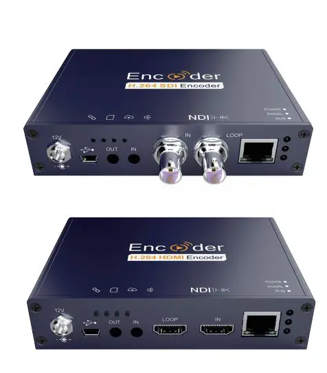
This product is divided in to SDI or HDMI interface, Please configure based on what you purchased.
Kindly note: This is only Quick Start Guide, if there any questions, please contact the supplier or visit website for more details
01 Packing list
Packing list
- Encoder*1
- DC 12V/1A Adaptor*1
- USB Ta l l y * 1 .
- Manual*1
- Warranty card*1
NOTE:
There will be some difference because of the updating of the device .
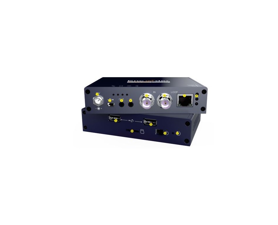
02 Device interfaces

- Power NOTE:
- Mini USB
- Audio out
- Audio in
- SDI IN/ HDMI LOOP
- SDI LOOP/HDMI IN
- Ethernet
- Indicator
- USB extend
- TF card
- Power Switch
- Reset
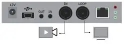
03 Device installation and connection
Connecting video signalConnect the SDI/HDMI signal from the source (such as a camera) to the SDI/HDMI input port of the device via a cable
NOTE:HDMI’s input interface is on the right
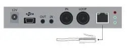
Connect NetworkConnect the network cable to the Ethernet port of the device, and connect the other end to the network switch or directly to the network port of the computer.
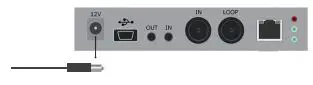
Connect the power supplyUsing the power adapter (DC 12v) to connect to the power connector of the device. After connected, turn on the power switch (Interface No.12) on the device. After the device is powered on, it starts working.
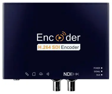
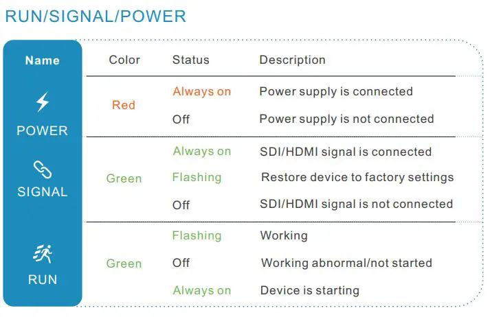
04 LED indicator
RUN/SIGNAL/POWER
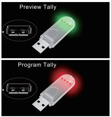
05 USB Tally
This unit supports Tally indication from any NDI switching device by connecting the external Tally device that comes in the package with the USB port of the encoder.
When the NDI source is output to NDI receivers such as VMIX, Trickster, etc. and when switch to Program or Preview, the encoder receives the notification and changes the colour on the “Tally” device, as shown in the figure below:
06 Video/ Audio source
Video/audio source selection
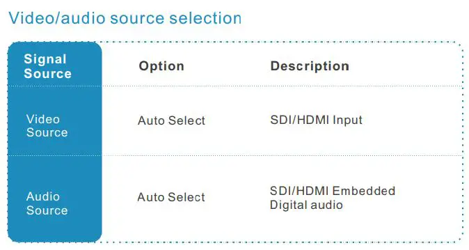
NOTE:Select the sub-functions “Video Source Selection and Adjustment” and “Audio Source and Volume Adjustment” of the “Video/Audio Adjustment” function on the web management interface to configure the video and audio source selection.
07 Device login and network configuration
Default IP address and web loginThe Failsafe IP address is 192.168.1.168 with subnet mask 255.255.255.0. Normally, you don’t need to modify this IP address.
Login the WEB ConsoleIf login for the first time, please use Failsafe IP address You can access http://192.168.1.168, to login the web console.Login username admin password admin
![]()
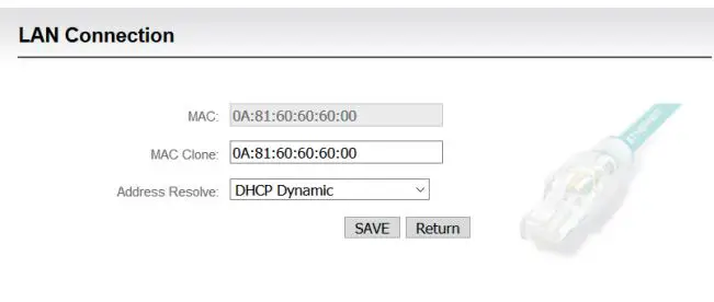
IP address configurationAfter login, you can configure the IP according to the network, the IP will be use for pushing and device management. You can configure it to manually set the IP or DHCP.( Default set is DHCP )
08 NDI|HX driver installation
Currently our encoders adopt compressed NewTek NDI|HX technology. Before your using, clients need to download NDI NDI|HX driver from https://www.newtek.com/ndi/tools/#.

NOTE:Encoder temporarily does not support RTSP pull. When NDI is connected, the default RTSP channel of the main stream of the encoder is encrypted, and the direct pull-out will be displayed as a mosaic state.
A NDI|HX driver is required to install before streaming.
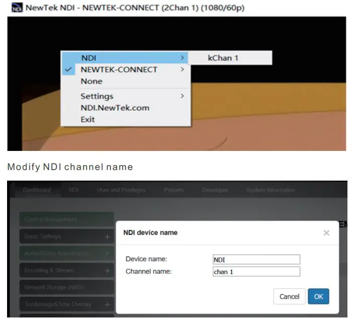
When there are several NDI encoders in the same network, as default Channel is the same, clients needs to set different Channels for different devices.
09 NDI discovery and connection
It is compatible with NewTek NDI®. When the device is in the same network as the Studio Monitor software(others like OBS, vMix, etc.), the device can be automatically discovered.
10 RTMP Live Streaming
Add streaming serviceOur device’s H.264 main/sub stream supports adding up to 8 same or different streaming media service, to meet your needs of adopting same/different stream media protocols for multi-goal pushing. On the management interface of “Encoding & Stream-Encoding and Stream Settings”, for main/sub stream to choose “add one stream service”, users can add the needed service type.
Add RTMP pushing streaming serviceCurrently main video live streaming platforms require “RTMP” service. After adding RTMP pushing service, click set icon to configure RTMP parameters.
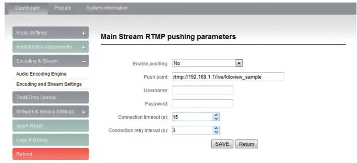
NOTE:This is an example of RTMP to introduce the configuration of push flow. Other push flow methods can be login to the device page for detailed configuration.
Take YouTube for an example“Streaming point” is RTMP address given by platform ( Take YouTube as an example ). ( Other platforms are similar, if questions please contact platform technical support for help ).
RTMP push-flow must first get a push-flow URL address from the platform Login to YouTube, got below address:
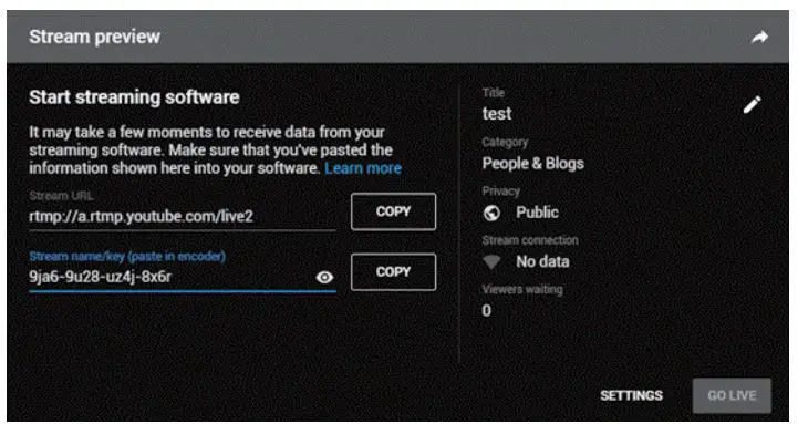
Streaming point should be like Server URL + Stream name/key, for example: http://a.rtmp.youtube.com/live2/9ja6-9u28-uz4j-8x6r
After you get the RTMP URL address, you need to set it up in the encoder. If the platform requires user name and password verification, you also need to fill in the corresponding parameters in the encoder.
NOTE:In the case of rtmps push mode, fill in rtmps URL at Push point and set Use old RTMP version to yes, so that it can be supported.
11 Restore factory settings
Restore factory settings
If users change parameters that lead encoder couldn’t work (typical situation is to change network address, so that it couldn’t be visited encoder by network.), users could restore factory setting to default value.
Two methods for restoring factory settings:
①Via the WEB interface, “Basic Setup > restore factory settings” function;②Through RESET button:
On the dashboard, there is button of Pressing on RESET button for 5 seconds, device will restore factory settings. Restoring factory setting will lead to the device hard restart, restarting course will last 1 minute.
NOTE:after restoring factory setting, below parameters will be turned to default value:
- Login password will be as admin;
- IP address will be restored as 192.168.1.168, subnet mask will be 255.255.255.0;
- All encoding parameters of video and audio will be restored to factory default value;
- Media transmission parameters will be restored as factory default value.
12 Firmware upgrading
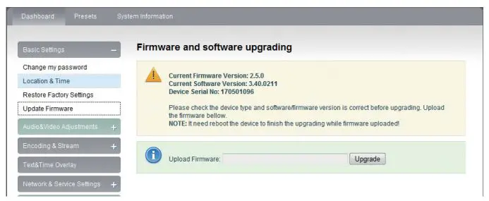
The encoder supports online firmware upgrading. Through the “Basic Settings-Firmware Upgrade” of the web management interface, you can upload the firmware online.
Upgrading diagram
NOTE:
- The device will restart automatically after upgraded, and recover to the default settings. User can upgrade the software version of device. Click “Browse” to select the upgrade file, and click to upgrade the device. The upgrade process is slow, around 30s to 1second, please be patient.
- After finish upgrading, check whether the version information of the latest firmware is consistent with the expected status through the System Status-Software Version of the web interface.
13 Quick Reset and reboot
Quick reset and reboot“Quick Reset” is quickly reset the video encoding function of encoder. When the video signal instability or improper parameter setting cause the encoder does not work, try to set the device quickly reset. The quickly reset probably need to wait 3 seconds or so.
“Reboot” is for encoder performs a warm reboot, when the encoder still does not work after quick reset, please try to reboot the device. Device rebooting lasts around 20s.
 report this ad
NOTE:Select “Quick Reset”, current encoding will be suspended for a while. Select “Reboot’, the encoder will warm reboot. Under some circumstances, reboot may be with the help of cold reboot: power down then power up the device.
References
[xyz-ips snippet=”download-snippet”]