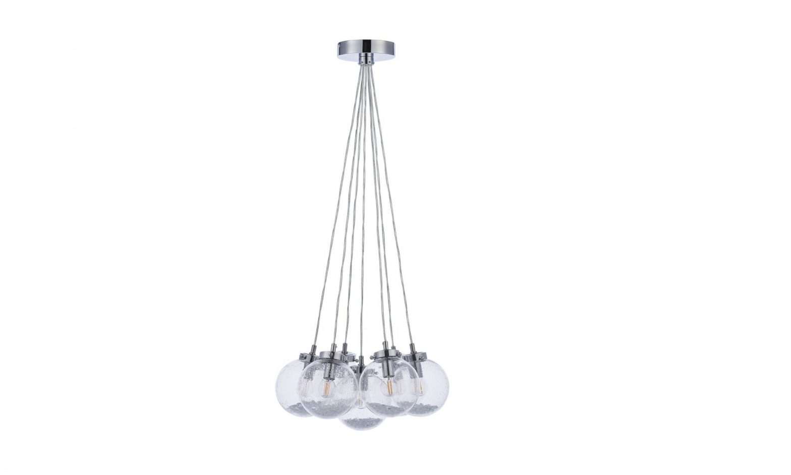
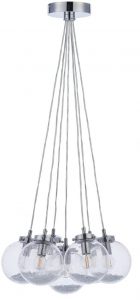
ENDON Harbour Drop 1 & 7-Light Pendant Fitting Instruction Manual
Safety Warnings
- This product is only suitable for connection to a 240V~50Hz supply in accordance with current IEE wiring regulations. It should be installed in accordance with local building regulations and is for domestic use only. It is not suitable for a bathroom location.
- Before installing your light fitting always switch off the mains supply and remove the appropriate fuse or switch off the appropriate circuit breaker before commencing installation.
- This is a Class I product. This Fitting does not require an Earth, and Live or Neutral must not be connected to Earth. The terminal blocks are supplied according to requirements of the fitting.
- Never fit bulbs of a higher wattage than those specified on the label, as these may cause overheating and damage the fitting.
- This product contains very delicate parts be careful during handling and maintenance to avoid breakage.
- If you are in any doubt about your competence please consult a qualified electrician.
- If any modification is made it will invalidate the warranty and may render the product unsafe.
Care Information
Allow 10 minutes to cool before replacing, adjusting or cleaning. Clean with a dry cloth only. Do not use liquid or abrasive cleaners on this product.
Assembly/ User Instructions
Before you start:Please read these instructions carefully before fitting and retain for reference. Check the packaging and make sure that you have all the required parts. Follow each assembly step in order to prevent incorrect assembly. Ensure that the product is fully assembled as illustrated before use.Please note – This instruction covers both 1 & 7-light versions of this fitting.
| The Light pack contains: | The following tools may be required: |
| Light fitting. | Selection of cross and flat head screwdrivers. |
| Terminal connection block(s). | Electric drill and assorted drill bits |
| Fixing pack. | Wire strippers. |
| 1 or 7x glass shades | Electrical insulation tape. |
| 1 or 7x bag of glass beads |
These assembly diagrams are intended as a guide if in doubt consult a qualified electrician.
- Decide on the position of the light fitting, or remove existing light fitting. Note the position of the electrical connections. Ensure there is a solid mounting surface, preferably a wooden joist or joist bridge to support the weight of the light fitting.
- If you want to reduce the overall length of the fitting it is essential that this is done before the fitting is mounted to the ceiling, or connected to the mains supply. Push the clutch up to release the support wire, then pull it through the ceiling cup until the desired length is reached, then release the clutch ensuring the wire is gripped. The cable must now be shortened and the excess cable cut and re-connected to the terminal block. Feed the cable up through the plastic bush and form a loop above the ceiling cup, moving the figure of 8 cable restraint down the exposed cable.NOTE: The electric cable must always be longer than the support wire to prevent strain being placed on the cable. If you are unsure about your ability to do this, we recommend you contact a qualified electrician.
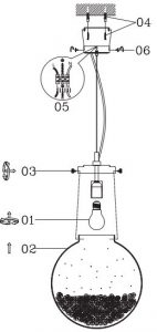
- Fit the bulbs (1). NOTE: Never fit bulbs of a higher wattage than those specified on the label (as these may cause overheating and damage the fitting).
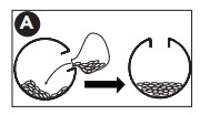
- Carefully decant one bag of beads into each glass shade – see inset diagram A.
- Affix the shades to the fitting by using the thumb screws (3).
- Remove the two side screws (6) and retain for re-use. Use the fixing bracket as a template to mark the screw holes. Make the screw holes and secure to the ceiling with appropriate screw fixings (4).
- Support your fitting and connect the house wiring to the terminal block (5) see expanded wiring details below.NOTE: This is a Class I fitting and must be earthed. The 4th terminal block connector is used for the “loop” wires of the “Ring Circuit”. There may be more than one set of cables in the “loop” connections. If there is a “Ring Circuit” and you do not understand the connections you must consult an electrician. Any loose terminal blocks not secured to ceiling cup should always be covered with 2 layers of good quality insulation tape.
- Secure the ceiling cup over the bracket by using the screws (6) removed in Point 6.
- Turn on the power and test.
[xyz-ips snippet=”download-snippet”]