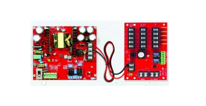
ENFORCER EAP-3D5Q Access Control Power Supply, Five Outputs User Manual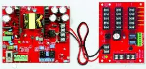
Features
- Input 110~240 VAC, fused at 3.15A
- 5 Outputs individually fused (PTC, 1.1A), in both fail-safe and fail-secure modes
- DC Output failure supervision relay
- Filtered and electronically regulated outputs
- Individual LED status indicators for AC input,DC output, and channel outputs
- Adjustable output voltage to compensate for voltage drop
- AC Power failure supervision relay
- Over-current fuse-protected AC input
- 12/24 VDC Outputs, field selectable
- Battery failure / low battery supervision relay
- Built-in back-up battery charger (Batteries not included)
- Automatically switch to backup battery if AC fails.
- Selectable 2.2kΩ End-of-Line (EOL) resistor for AC failure and battery failure supervision relays via DIP switch
- Auxiliary output relay
- Selectable delay timer (5sec, 5min, 5h) for AC failure supervision relay via DIP switch
- Board designed with LED overload indicator and automatic shutdown for short-circuit protection.
- Heavy-duty steel case with removable cover for easy access to connections
- Ventilation holes to prevent heat buildup
- Room for two 7Ah batteries (or two 12Ah batteries for EAP-5D5Q) (Batteries not included)
- Knockouts for power connections and optional cam lock
Parts List:
- 1x Power Supply / Enclosure
- 1x Cable management nut
- 1x Manual
- 2x Screws for the enclosure door
- 3x Wires for backup battery (red, black, white)
- 1x Cable management clamp
- 1x 6ft Power cord with ground wire
- 1x Protective plastic bushing for power cable
Specifications:
| Model | EAP-3D5Q | EAP-5D5Q |
| Operating voltage | 110~240 VAC | |
| Output voltage | 12/24 VDC (selectable) | |
| Output voltage range (adjustable) | 12VDC | 12~13 |
| 24VDC | 23~25 | |
| LED Status indicator | DC | Red=12VDC, blue=24VDC for each output |
| AC | Green, input | |
| Current rating | , | , |
| Supervision relays | EOL: Selectable ON (2.2kΩ) or OFF, dry relay output | |
| Power failure supervision relay | ||
| Auxiliary supervision relay | ||
| AC Input fuse rating | 3.15A | |
| AC Power cord | 6ft (1.8m) | |
| Operating humidity | 85% maximum | |
| Operating temperature | -4°~149° F (-20°~65° C) | |
| Dimensions | 121/8″x121/4″x39/16″ (308x311x90 mm) | 1413/16″x145/16″x41/8″ (377x363x105 mm) |
| Weight | 10-lb 2-oz (4.6kg) | 11-lb (5kg) |
Overview
Built-in output overload / short-circuit protection – If an overload occurs, the motherboard’s output voltage output will drop. The voltage drop will depend on the extent of the overload. The greater the overload the greater the voltage drop. If the overload is extensive, the voltage output will become intermittent and the red LED will start flashing. When the overload is removed, the motherboard will automatically restart normal output. If an output short-circuit occurs, the motherboard will automatically shut the output down and the red LED will turn off. When the short-circuit is removed, the motherboard will automatically come back on line.
Installation:
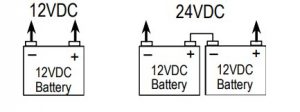


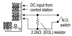
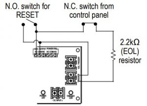

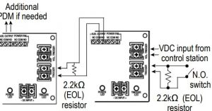 Fig. 7 Multiple PDM momentary trigger for wet and/or dry N.O. switch
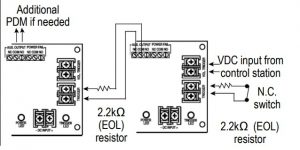 Fig. 8 Multiple PDM momentary trigger for wet and/or dry N.O. switch
IMPORTANT:The ENFORCER Power Supply is not waterproof or weatherproof. Therefore, it must be mounted indoors where it will not be exposed to rain or other moisture.
Installation must be done by qualified personnel, and should conform to local and all other applicable codes.
- Choose a mounting location out of sight and protected from moisture and weather, but easily accessible for future servicing.NOTE: Make sure the space where the enclosure is to be mounted has adequate ventilation. Otherwise, heat buildup inside the enclosure could damage the electronic parts.
- Locate the enclosure mounting holes. Using these holes as a template, mark the location of the 4 screws on the wall with a pencil.
- Thread the AC power cord through the protective plastic power cord bushing and then through the power cord hole in the enclosure, snapping the bushing into place. Secure the power cord with the cable management clamp.
- Attach to the wall by first screwing in two 3 /16″ x 1″ (4×26 mm) upper screws using plastic wall anchors if needed (both not included) until the gap between the wall and the screw head is approximately 1 /4″ (6mm).
- Hang the enclosure on the two upper screws using the enclosure’s upper screw holes and adjust the proper location of the enclosure. Screw in the two lower screws. Then securely fasten the upper and lower screws.
- Run wires from the access control devices to the power supply. The enclosure has knock-outs on the side, top, bottom, and rear panels for running cables. Punch out the appropriate knock-outs.
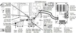
- Set the desired DC output voltage (12 or 24 VDC) of the power supply using the sliding switch (see “Overview,” pg. 3). The default is 12VDC.
- Connect the backup battery to the backup battery terminal (see Fig. 1). Check voltage output reading of the power distribution module (PDM). If the green LED is ON, and the voltage reading of the PDM’s five channel outputs are the same as the backup battery terminal’s voltage reading, this indicates that the power supply is working properly. Disconnect battery after testing.
- Connect the power input wires of the access control devices or accessories to the power distribution module (PDM, see “Overview,” pg. 2). Observe correct polarity. For fail-secure devices, connect positive to terminals marked “POS. OPEN LOOP” and negative to terminals marked “NEG.” For fail-safe devices, connect positive to terminals marked “POS. CLOSE LOOP” and negative to terminals marked “NEG”.IMPORTANT NOTES/WARNINGS:a. To avoid risk of electrical shock, the ground terminal of the “AC INPUT” MUST be connected to earth via the power cord.b. If the “Trigger” terminal block function is to be used, a 2.2kΩ resistormust always be connected to the “Trigger” terminal block as in Fig. 2.c. Maximum total current connected to the power supply terminal must not exceed the power supply’s total current capacity ( and ).d. Check the output voltage reading of the power supply as stated above and double check the specified operating voltage of each device before connecting it to the power supply to avoid potential damage.e. Use at least 18-gauge wires to minimize voltage drop. The thinner the wire, the greater the voltage drop.f. Keep power limited wiring separated from non-power limited wiring (AC input, battery wiring) by a minimum distance of 1 /4″ (7mm) and use separate knockouts in the enclosure.
- Connect a visual or audio indicator (such as siren or strobe light) to the ACfailure and battery-failure / low battery supervision relays if needed (see “Overview, pg. 2). Use between 22AWG to 18AWG wire size.
- Follow the connection diagrams shown in Fig. 3~8 to trigger the PDM from a wet and/or dry contact switch from the control station.
- Connect a visual or audio indicator (such as siren or strobe light) to the power fail supervision relay and Auxiliary output relay if needed.
- Double check to ensure everything is connected properly. Connect the AC power (110~240 VAC). The AC LED & DC LED on the main board (red=12VDC, blue+24VDC), and the power LED on the PDM should turn ON to indicate the power supply unit is working properly.
- Reconnect the backup battery. Again ensure the voltage output reading of the PDM is within the normal working range. Check the DC output voltage reading at the end of the wire pairs where it is to be connected to the device. If the output voltage reading falls below the minimum voltage requirement of the device, use a small screwdriver to carefully turn the potentiometer marked “VR1” located on the PCB. Turn clockwise to increase the voltag and counterclockwise to decrease the voltage (see “Overview,” pg. 2).IMPORTANT NOTES:a. Do not adjust the potentiometer unless absolutely necessary. Adjusting the potentiometer alters default factory settings.b. The potentiometer adjusts the voltage of all output wire pairs. Check each device carefully. An output voltage in excess of the specified voltage level of the device may cause damage.
- Once the desired DC output voltage is achieved, connect the wire pairs to the device.ProgrammableFeaturesa. AC-failure Relay Output Delay Timer — Program the AC-failure relay delay timer at 5sec, 5min or 5h using the DIP switch (see “Overview,” pg. 2). The default setting is at 5sec.b. 2.2kΩ End-of-Line (EOL) Resistor — The end-of-line 2.2kΩ resistor for AC-failure relay and battery-failure / low battery supervision relays () can be activated independently using the DIP switch (see “Overview,” pg. 2, default ON).c. Battery Presence and Low Battery Monitor — When the LB MODE DIP switches are in the ON position, the power supply will monitor the battery to verify if it has sufficient voltage to run the power supply in case of AC power failure. Selecting “OFF” will stop monitoring of battery status and will charge battery continuously. It can take up to 5 minutes to alert you of a battery failure. The length of time the system will run will be limited by the overall capacity and the age of the batteries and the amount of load being drawn off the power supply.
- Connect the backup battery to the backup battery terminal (see Fig. 2 and “Overview,” pg. 2, default ON).
- Close the enclosure door and secure it with either the provided machine screws or an optional cam lock.
Table 1: Terminal Functions
| Mon Board | Power Distributon Module (PDM) | ||
| Legend | Functions | Legend | Functions |
| A E N | To connect 110.240 VAC power rir for active wee. ‘E’ for earth or ground wire. and ‘N’ for neutral wire | TRIGGER | Used to conned NO or NC input trigger sgnal (22k0 EOL resistor) from access contrd panel. A shun or open cum t will transfer power from ‘PCS CLOSE LOOP’ to “PCS OPEN LOOP.’ |
| BAT.FAIL | Used to notify battery failure. Dry contact relay rated at 3A024VDC. If backup battery is not connected proper/ or f voltage output falls below I I.2VDC for 12VDC setting (or 22.7VCC for 24VDC setting, the connected warning device wi be activated. | VOL TRIGGER | Used to conned wet (5-30 VDC) Input trigger sgnal from access control panel. A short circuit or open WWI will transfer power from ‘PCS CLOSE LOOP’ to ‘PCS OPEN LOOP.’ |
| POWER FAx | Used to notify Ices of DC power. Day cortact relay rated 3A024VDC. ft VDC input to the PDM is Interrupted. roe connected warning device ‘v• be activated. | ||
| – BAT . | Used to charge the backup battery. Maxenum thargIng current is SA | AUX OUTPUT | Used to activate other ern:diary device when trigger sgnal isreceived from the ‘TRIGGER’ or–VOL TRIGGER fermiers |
| – DC . | 12 of 24 VDC Output terminal from main board | – DC INPUT • | 12 or 20 VDC Input from main board |
California Proposition 65 Warning: These products may contain chemicals which are known to the State of California to cause cancer and birth defectsor other reproductive harm. For more information, go to www.P65Warnings.ca.gov.
WARRANTY: This SECO-LARM product is warranted against defects in material and workmanship while used in normal service for one (1) year from the date of sale to the original customer. SECO-LARM’s obligation is limited to the repair or replacement of any defective part if the unit is returned,transportation prepaid, to SECO-LARM. This Warranty is void if damage is caused by or attributed to acts of God, physical or electrical misuse or abuse, neglect, repair or alteration, improper or abnormal usage, or faulty installation, or if for any other reason SECO-LARM determines that such equipment is not operating properly as a result of causes other than defects in material and workmanship. The sole obligation of SECO-LARM and the purchaser’s exclusive remedy, shall be limited to the replacement or repair only, at CO-LARM’s option. In no event shall SECO-LARM be liable for any special, collateral, incidental, or consequential personal or property damage of any kind to the purchaser or anyone else.
NOTICE: The SECO-LARM policy is one of continual development and improvement. For that reason, SECO-LARM reserves the right to change specifications without notice. SECO-LARM is also not responsible for misprints. All trademarks are the property of SECO-LARM U.S.A., Inc. or their respective owners. Copyright © 2021 SECO-LARM U.S.A., Inc. All rights reserved.
SECO-LARM® U.S.A., Inc.
16842 Millikan Avenue, Irvine, CA 92606
Phone: (949) 261-2999 | (800) 662-0800
Website: www.seco-larm.com
Email: [email protected]
References
[xyz-ips snippet=”download-snippet”]