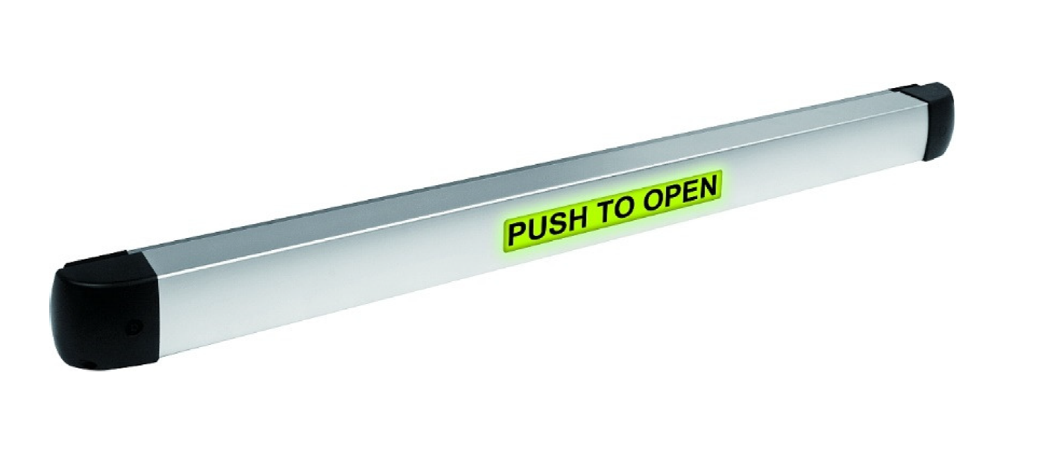
ENFORCER SD-961A-36SLQ Illuminated Push-to-Open Bar
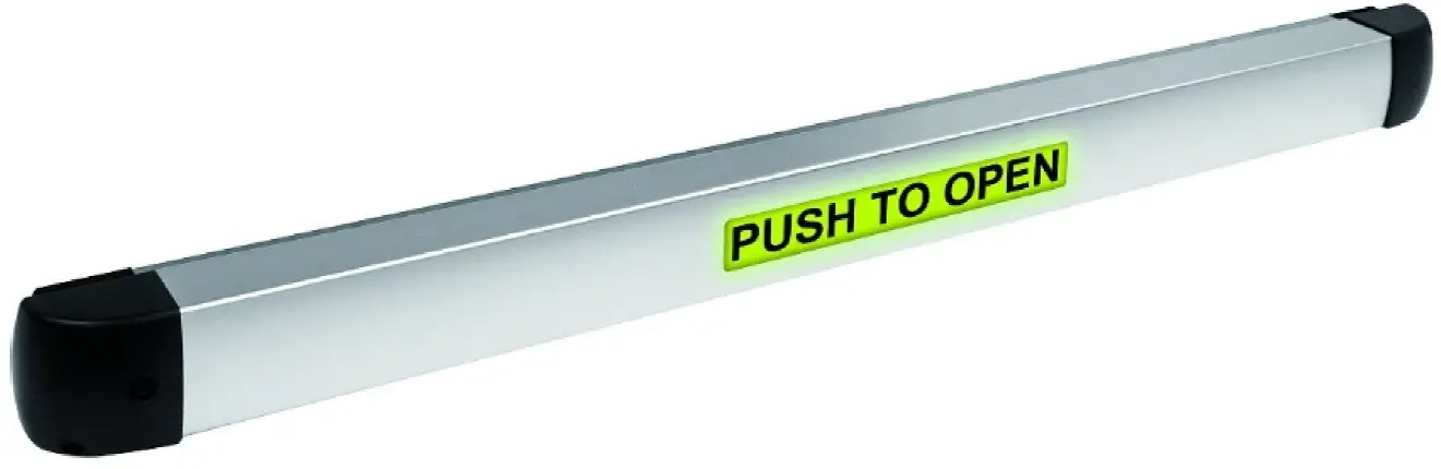
The ENFORCER Illuminated Push-to-Open Bar works with an external electric strike or maglock to provide egress from a protected area. It can work in stand-alone mode or as part of an access control system, but also can be locked open by key. Buzzer, output timing, and LED function and colors are also customizable.
Features:
- Provides convenient on-door egress.
- LED makes it easy to see the status.
- Can be stand-alone or connected to an access control system.
- Two built-in non-latching (momentary), dual-contact outputs (NO/NC/COM) rated at ≤, adjustable 0.5~60 sec
- Dogging – standard dogging with hex key..
- For 36″ doors – actual length: 337/16″ (85cm).
- Can be cut to fit smaller doors, minimum 235/8″ (60cm).
- Large LED shows red in standby and green when triggered, but is programmable red/green/blue by an access control panel.
- Blinking LED and buzzer programmable for relock warning.
- Built-in buzzer indicates unlocked (selectable, up to 92dB)
ENFORCER Illuminated Push-to-Open Bar
Specifications
| Operating voltage | 12~24 VDC | |
| Power consumption | , (max.) | |
| Contact load | ≤ | |
| Outputs | NO/NC/COM x2 | |
| Trigger duration | 0.5~60 seconds (adjustable) or dogged open | |
| Buzzer | Up to 92dB (adjustable) | |
| LED
Indicator |
Colors | Stand-alone red/green, Controlled red/green/blue |
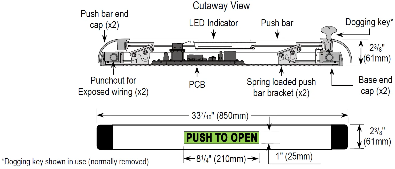
| Size | 81/4″x1″ (210×25 mm) | |
| Door width | 36″ (91.4cm), minimum 235/8″ (60cm) | |
| Operating temperature | 32°~150° F (0°~70° C) | |
| Dimensions | 337/16″x23/8″x23/8″ (850x61x61 mm) | |
| Weight | 4-lb 10-oz (2.1kg) |
Parts List:
- 1x Illuminated push bar
- 5x Machine screws
- 1x Dogging key
- 1x Keyhole cover
- 2x Self-stick wiring anchors
- 1x Manual
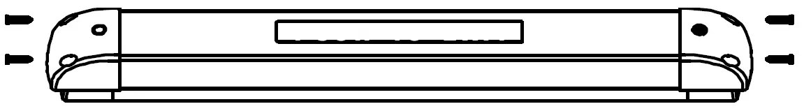
Overview:
Installation
Please read the manual carefully before beginning installation.
- Hold the push bar unit on the door at the desired height, ensuring that there is sufficient space on both ends as noted below. With a pencil, mark the lower edge of the base and the edge of the base end cap on the latch side of the door.NOTES:
- Leave at least 9/16″ (1.5cm) space between the door edges and both ends of the base.
- Level with a bubble level.
- The height of the push bar from the floor may be subject to local regulations.
- Usually, the bar is centered but for wider doors it can be closer to the latch side.

- Remove the two screws from each of the push bar end caps and remove the end caps.If you need to cut the push bar to fit a door narrower than 36″ (91.4cm), skip to step 4.
- For doors at least 36″ (91.4cm) wide, mount the bar to the door. Using the lines drawn in step 1, hold the base in place and mark 4 mounting screw holes (and the wiring hole if wiring runs through a hollow door using an electric transfer hinge). Drill holes, making sure not to go all the way through the door and mount on the door.NOTE: The wiring connection is normally on the hinged side of the door.
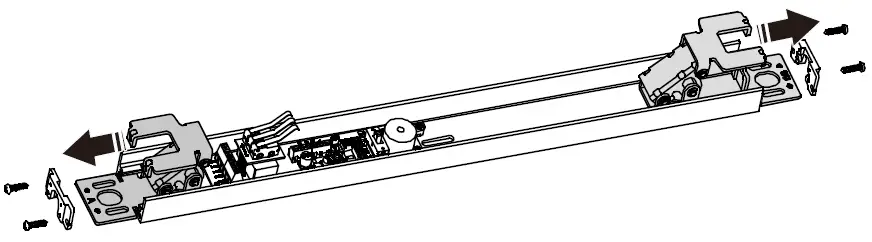
- Remove the mounting bracket from one end of the push bar.
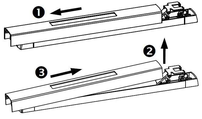
- Taking care not to damage the LED wiring harness, 1 slide the push bar in the direction of the removed endplate until it is free of the opposite push bar bracket, 2 lift the free end, and 3 slide in the other direction until it is free.
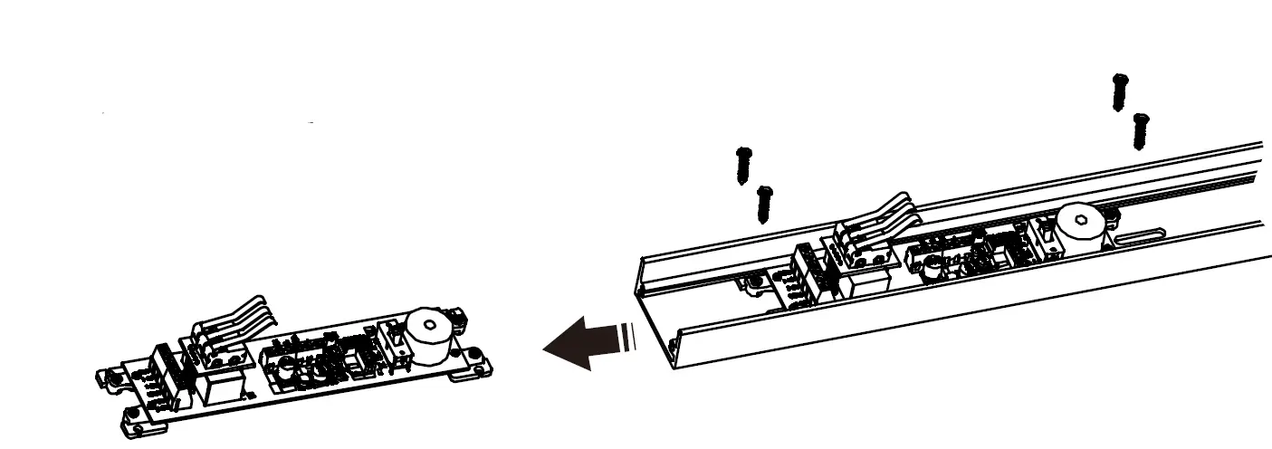
- Unplug the LED cable from the PCB.If you do not need to cut the push bar, skip to step 8.
- To cut the push bar to fit a narrow door:
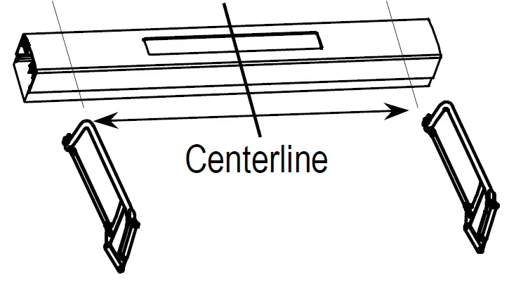
- Unscrew and remove both base end caps.
- Remove the screws and slide the two push bar brackets off the base.
- Remove the screws and slide the circuit board off the base.
- Measure the door width and subtract from 36″ (91.4cm). Divide the result in half and carefully mark the base and push bar to cut an equal amount from each end of both.NOTES:
- The minimum cut length is 235/8″ (60cm).
- Both push bar and base must be the same length and the cuts must be at a 90° angle.
- Replace the circuit board, push bar brackets, and base end caps (reversing steps 7a~7d,). Mount the base to the door as in step 3.
- Unscrew and remove both base end caps.
- For exposed wiring or an armored cable, punch out the scored wiring hole on the side of the base end cap and the scored piece from the corresponding push bar end cap.
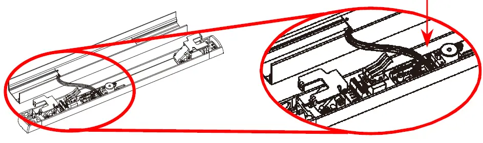
- Run the wires through the base cap hole and connect to the terminals (see Sample Installations and Wiring Diagrams, pg. 4). If using an armored cable, attach the cable.
- Plug the LED wiring harness back in to the PCB, replace the push bar, and reattach the end caps, reversing steps 4~6.

 If you need to cut the push bar to fit a door narrower than 36″ (91.4cm), skip to step 4.
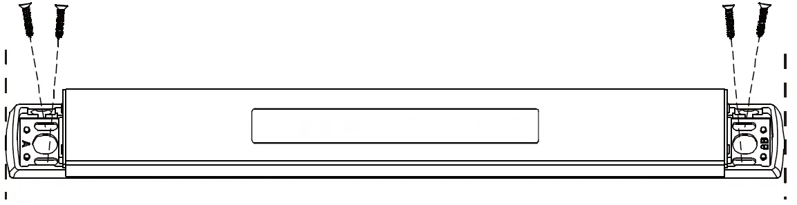 NOTE: The wiring connection is normally on the hinged side of the door.
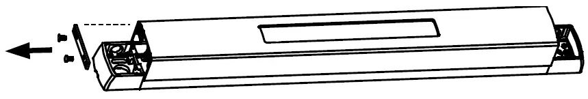
 If you do not need to cut the push bar, skip to step 8.
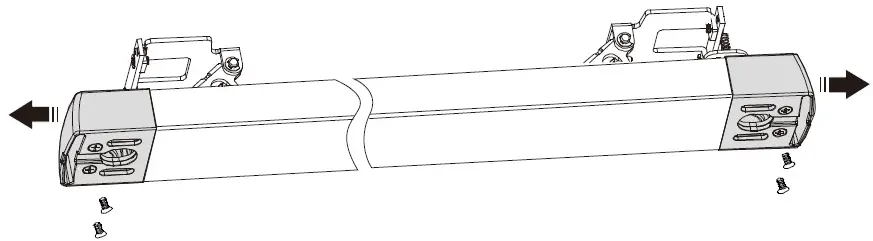
 NOTES:


Locking the Bar Open:Included with the push bar is a dogging key. To lock the push bar closed (to allow two-way, uncontrolled access to the protected area), remove the keyhole cover, push the bar in all the way, and turn the bolt with the dogging key. To release the bar, turn the bolt to its original position.
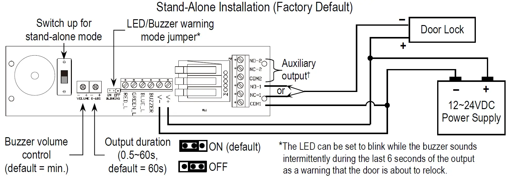
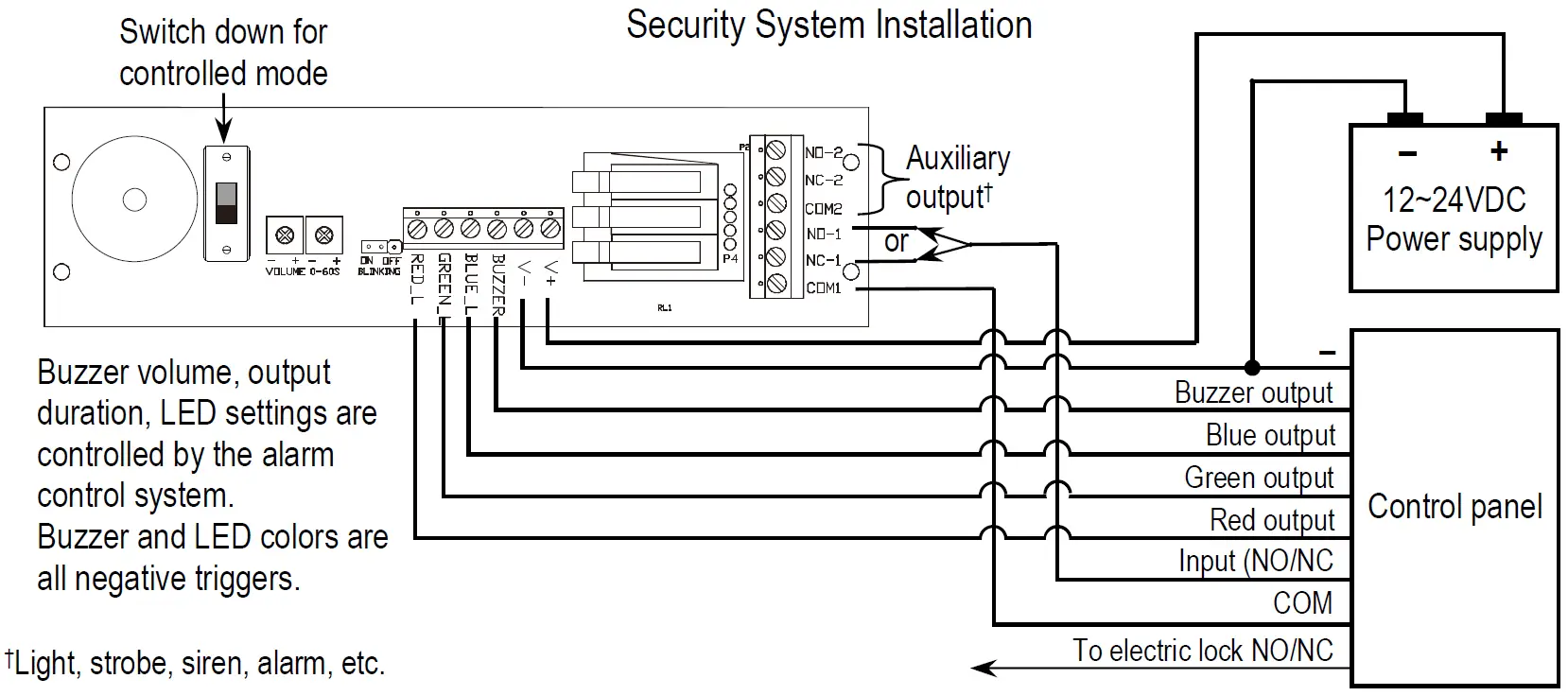
Sample Applications and Wiring Diagrams:
California Proposition 65 Warning: These products may contain chemicals which are known to the State of California to cause cancer and birth defects or other reproductive harm. For more information, go to www.P65Warnings.ca.gov.
WARNING: The push bar is not weatherproof. Do not mount on exterior surfaces or where exposed to rain.
IMPORTANT:
- The height at which the push bar is mounted may be subject to local regulations.
- It is the responsibility of the installer and/or end-user customer to ensure the Illuminated Push-to-Open Bar meets all local regulations regarding the use of push bars for access security, including: suitability for doors accessed by disabled persons and suitability for fire doors (the push bar is not fire-rated).
WARRANTY
This SECO-LARM product is warranted against defects in material and workmanship while used in normal service for one (1) year from the date of sale to the original customer. SECO-LARM’s obligation is limited to the repair or replacement of any defective part if the unit is returned, transportation prepaid, to SECO-LARM. This Warranty is void if damage is caused by or attributed to acts of God, physical or electrical misuse or abuse, neglect, repair or alteration, improper or abnormal usage, or faulty installation, or if for any other reason SECO-LARM determines that such equipment is not operating properly as a result of causes other than defects in material and workmanship. The sole obligation of SECO-LARM and the purchaser’s exclusive remedy, shall be limited to the replacement or repair only, at SECO-LARM’s option. In no event shall SECO-LARM be liable for any special, collateral, incidental, or consequential personal or property damage of any kind to the purchaser or anyone else.
NOTICE: The SECO-LARM policy is one of continual development and improvement. For that reason, SECO-LARM reserves the right to change specifications without notice. SECO-LARM is also not responsible for misprints. All trademarks are the property of SECO-LARM U.S.A., Inc. or their respective owners. Copyright © 2021 SECO-LARM U.S.A., Inc. All rights reserved.
SECO-LARM ® U.S.A., Inc.16842 Millikan Avenue, Irvine, CA 92606Phone: (949) 261-2999 | (800) 662-0800
Website: www.seco-larm.comEmail: [email protected]
![]()
References
[xyz-ips snippet=”download-snippet”]