
ENFORCER SK-910RB2Q One- and Two-Channel RF Receivers
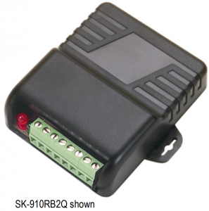
One- and Two-Channel RF Receivers
- Flexible operating voltage: 11~24 VAC/VDC
- Independently programmable channels
- Compatible with all SECO-LARM transmitters of the same frequency
- 5 Relay output functions
NOTE: Operating range will vary greatly depending on the installation and operating environment.
| Model |
Channels |
Output |
Frequency |
| SK-910RBQ |
1 |
10A Form “C” relay |
315MHz |
| SK-910RB-4Q* |
1 |
10A Form “C” relay |
433.92MHz |
| SK-910RB2Q |
2 |
10A Form “C” relay |
315MHz |
| SK-910RB2-4Q* |
2 |
10A Form “C” relay |
433.92MHz |
Also Available from SECO-LARM
SK-910R3Q…………. Three-channel receiver, 10A Form “C” relays, 315MHzSK-910R4Q ………… Four-channel receiver, 10A Form “C” relays, 315MHZSK-910RAQ ……….. One-channel mini-receiver, 3A Form “C” relay, 315MHzSK-910RAVQ …….. One-channel mini-receiver, 5A transistor ground output, 315MHzSK-910RAV2Q ……..Two-channel mini-receiver, 3A transistor ground outputs, 315MHz
NOTE: This manual does not cover the three- and four-channel receivers and mini-receivers listed here. All receivers are also available in 433.92MHz versions. Please contact SECO-LARM or visit www.seco-larm.com for model numbers and more information.
Introduction
The SK-910RBQ series of wireless receivers meet the growing demand for receivers with multiple, independently-controlled output functions. These RF receivers are compatible with both code hopping and fixed code transmitters (see pg. 4 for a note about compatible transmitters and visit www.secolarm.com for a full list). The receivers can be used to remotely control a variety of home automation devices such as garage door openers, lights, motorized gates, lifts, or other devices.
Installation Notes
- Mount the receiver out of sight in a location where it is not exposed to weather or moisture, and where it is not surrounded by metal. Metal will block the RF signal, resulting in a reduced range.
- For best range, pull the antenna wire as long and straight as possible. If the receiver receives interference from local RF activity (e.g., an airport or military base), the antenna wire can be folded.
IMPORTANT: DO NOT CUT THE ANTENNA WIRE.
ENFORCER One- and Two-Channel RF Receivers
Each receiver channel can learn the codes of up to 15 different transmitters on a first-in, first-out basis. Below is the procedure for code learning a new transmitter button.
- Press the channel mode switch of the desired channel for 3 seconds or more. The channel’s LED will start to flash quickly to indicate that it is in learning mode.
- While the LED is flashing, press the button of the transmitter to be learned one time. The receiver’s channel indicator LED will flash once to indicate the transmitter button has been successfully learned. After the button has been learned, the receiver will automatically exit learning mode. To learn further codes, repeat step 1 to re-enter learning mode.
NOTES:
- The channel mode switch(es) can be found at the rear of the receiver’s case.
- The channel’s indicator LED will flash a maximum of 15 seconds. If no transmitter button is pressed during this time, the receiver will exit code learning mode, and the LED will turn off.
- If the code being learned has already been learned, the channel indicator LED will turn steady ON and then start flashing again. The code will not be learned a second time.
- One channel can learn the codes of a maximum of 15 transmitter buttons. If you attempt to learn a sixteenth transmitter code, the earliest code learned will be deleted and the new code will be learned.
Clear Channel Memory
To clear all codes from a channel’s memory, press the channel’s mode switch for 3 seconds or more until the channel indicator LED flashes. Release, and then press the switch again for 3 seconds or more until the LED stops flashing. The LED will then flash twice to indicate that all codes associated with that channel have been deleted.
Display Channel Memory
To see how many codes have been learned by a channel, press that channel’s mode switch once. The number of codes stored in the channel’s memory is equal to the number of times the channel indicator LED flashes.
Programming Channel Relay Output Function
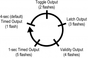
Each channel relay can be programmed for one of five output functions. SK 910RB2Q only: Each channel can be independently programmed to operate in a different function, depending on the user’s application. The five functions are:
- 4-Second Timed Output (default) – When the transmitter button is pressed, the relay will turn ON for 4 seconds.
- Toggle Output – Works much like a toggle switch to turn a device ON & OFF alternately. Press the transmitter button once, and the relay turns ON. Press the transmitter button again, and the relay turns OFF.
- Latch Output – Press the transmitter button once, and the relay turns ON and stays ON. The channel relay will remain ON regardless of whether a compatible transmitter button is pressed again or not. To turn the relay OFF, press the channel’s mode switch on the receiver once to reset.
- Validity Output – The channel will turn the relay ON for as long as the transmitter button is pressed.Note: Due to possible interference or drops in transmitter battery power while the transmitter button is continuously pressed (even for short periods of time), the receiver may lose the transmitter’s signal and turn the relay OFF.
- 1-Second Timed Output – When the transmitter button is pressed, the relay will turn ON for 1 second.
Selecting the relay output function:
- Hold down the channel function switch for 3 or more seconds. The channel’s LED will flash a number of times equal to the output mode that it is in.
- To change a channel’s function, press the channel’s function switch. Each press moves to the next function in the sequence as shown in the diagram to the right.
- After changing functions, count the number of times the channel LED flashes to verify the channel is set to the correct function.
- To exit function programming, hold the appropriate function switch for 3 seconds, or wait 15 seconds.
 NOTE: For a diagram of the PC board, including the location of the function switch(es), please see Overview, pg. 3.
 NOTE: For a diagram of the PC board, including the location of the function switch(es), please see Overview, pg. 3.
Overview
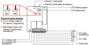
(PC board shown. Remove the front cover of the receiver to access the function switch(es) and terminal block.)
Channel Mode Switch Operation (One per Channel)
| Learn mode | Press and hold the channel mode switch for three seconds or more. |
| Clear memory | Press and hold the channel mode switch for three seconds or more, then when the LED starts flashing, press again for three seconds to delete all previously learned codes. |
| Reset latched output | If the channel was programmed for latch output, once the relay is turned ON with a transmitter button, press the channel mode switch of that channel once to turn the relay OFF. |
| Memory Display | Press and release the channel mode switch to show the number of codes stored. The LED will flash a number of times corresponding to the number of codes stored. |
LED Indication (One per Channel)
| Steady ON | Receiving signal from a transmitter button during normal operation, or indicates a transmitter button’s code already exists in the receiver’s memory during code learning. |
| Fast flash | Receiver is in code-learning mode or channel memory display mode, or during the programming channel output mode. |
| One flash | A transmitter button code was learned, or receiver channel is in 4-second timed output mode. |
| Two flashes | All previously learned transmitter buttons were deleted, or receiver channel is in toggle output mode. |
| Three flashes | Receiver channel is in latched output mode. |
| Four flashes | Receiver channel is in validity output mode. |
| Five flashes | Receiver channel is in 1-second timed output mode. |
| 0~15 flashes | During normal operation, pressing a channel mode switch will cause the channel indicator LED to flash. Number of flashes indicates the number of transmitter buttons currently stored. |
Extended Range Antenna (Optional
The SECO-LARM SK-91ERSD/ SK-93ERSD significantly extends RF receiver range with existing remotes. It comes with a 9ft (2.7m) cable that easily plugs into the 3-pin antenna port located on the RF receiver.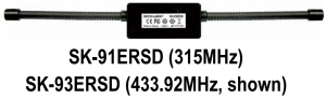
NOTES:
- Antenna range will vary greatly depending on the installation and operating environment.
- To use an extended range antenna, the loop marked “LP3” on the receiver PC board must be cut.
- To protect the antenna components and the RF receiver circuits, please turn off power to the RF receiver before cutting the loop “LP3” on the PC board and before connecting or disconnecting an external antenna.
- The SK-9xERSD is not weatherproof. For outdoor use, seal the case seams and connections with silicone sealant.
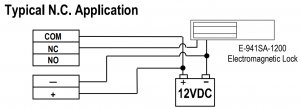
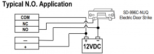
Sample Applications
Specifications
| Model | SK-910RBQ / SK-910RB2Q | SK-910RB-4Q / SK-910RB2-4Q |
| Operating frequency | 315MHz | 433.92MHz |
| Memory capacity | 15 transmitter button codes per channel | |
| Operating voltage | 11~24 VAC/VDC | |
| Operating current | Standby | |
| Active | per channel | |
| Relay contact rating | Form C or 120VAC per channel | |
| Connectors | Screw terminals, +, -, with NO/NC/COM per channel | |
| Operating temperature | -40°~167° F (-40°~75° C) | |
| Dimensions | 31/8”x29/16”x1” (80x65x25 mm) |
Compatible Transmitters
| 315MHz | 433.92MHz | |
| Fixed Code: 68 billion codes | SK-919 Series Fixed Code | SK-939 Series Fixed Code |
| CODEBUMP™: 18 quintillion (1.8×10¹⁹) codes | SK-917 Series CODEBUMP | SK-937 Series CODEBUMP |
California Proposition 65 Warning: These products may contain chemicals which are known to the State of California to cause cancer and birth defects or other reproductive harm. For more information, go to www.P65Warnings.ca.gov.
FCC/IC COMPLIANCE STATEMENTS
HIS DEVICE COMPLIES WITH PART 15 OF THE FCC RULES. OPERATION IS SUBJECT TO THE FOLLOWING TWO CONDITIONS: (1) THIS DEVICE MAY NOT CAUSE HARMFUL INTERFERENCE AND (2) THIS DEVICE MUST ACCEPT ANY INTERFERENCE RECEIVED, INCLUDING INTERFERENCE THAT MAY CAUSE UNDESIRED OPERATION.Notice: The changes or modifications not expressly approved by the party responsible for compliance could void the user’s authority to operate the equipment.IMPORTANT NOTE: To comply with the FCC RF exposure compliance requirements, no change to the antenna or the device is permitted. Any change to the antenna or the device could result in the device exceeding the RF exposure requirements and void user’s authority to operate the device.This device complies with Industry Canada licensee-exempt RSS standard(s). Operation is subject to the following two conditions: (1) this device may not cause interference, and (2) this device must accept any interference, including interference that may cause undesired operation of the device.
WARRANTY: This SECO-LARM product is warranted against defects in material and workmanship while used in normal service for one (1) year from the date of sale to the original customer. SECO-LARM’s obligation is limited to the repair or replacement of any defective part if the unit is returned, transportation prepaid, to SECO-LARM. This Warranty is void if damage is caused by or attributed to acts of God, physical or electrical misuse or abuse, neglect, repair or alteration, improper or abnormal usage, or faulty installation, or if for any other reason SECO-LARM determines that such equipment is not operating properly as a result of causes other than defects in material and workmanship.The sole obligation of SECO-LARM and the purchaser’s exclusive remedy, shall be limited to the replacement or repair only, at SECO-LARM’s option. In no event shall SECO-LARM be liable for any special, collateral, incidental, or consequential personal or property damage of any kind to the purchaser or anyone else.
NOTICE: The SECO-LARM policy is one of continual development and improvement. For that reason, SECO LARM reserves the right to change specifications without notice. SECO LARM is also not responsible for misprints. All trademarks are the property of SECO-LARM U.S.A.,Inc. or their respective owners. Copyright © 2021 SECO LARM U.S.A., Inc. All rights reserved.
![]() 16842 Millikan Avenue, Irvine, CA 92606 Website: www.seco-larm.comPhone: (949) 261-2999 | (800) 662-0800 Email: [email protected]
16842 Millikan Avenue, Irvine, CA 92606 Website: www.seco-larm.comPhone: (949) 261-2999 | (800) 662-0800 Email: [email protected]
 Order Part# 762-116-9%MI_SK-910RBxQ_210423.docx

References
[xyz-ips snippet=”download-snippet”]