![]() Quick Installation GuideENSSOO-ACENS5OOEXT-ACEnStationS-ACEnStationACENHSOOVersion2 .0Outdoor Access Point/Client Bridge
Quick Installation GuideENSSOO-ACENS5OOEXT-ACEnStationS-ACEnStationACENHSOOVersion2 .0Outdoor Access Point/Client Bridge
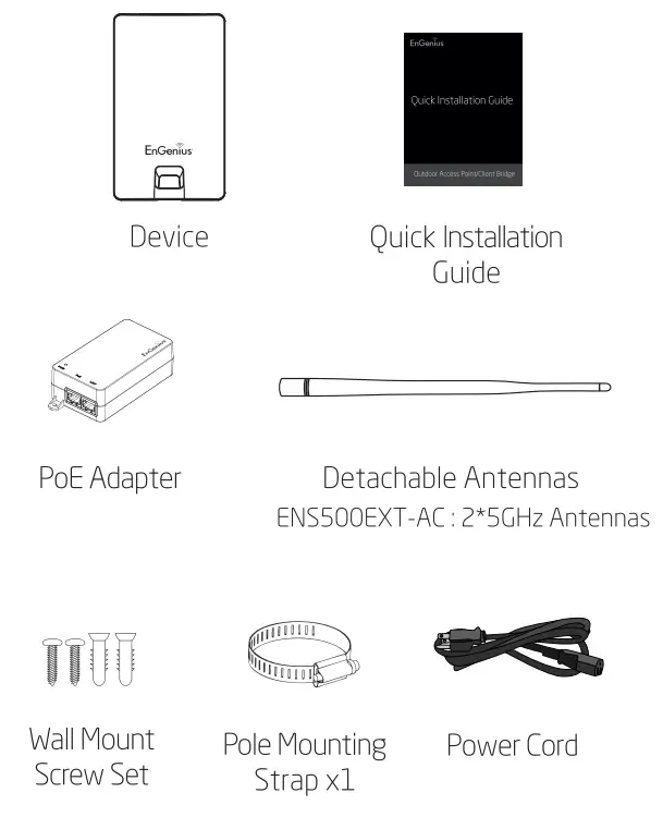
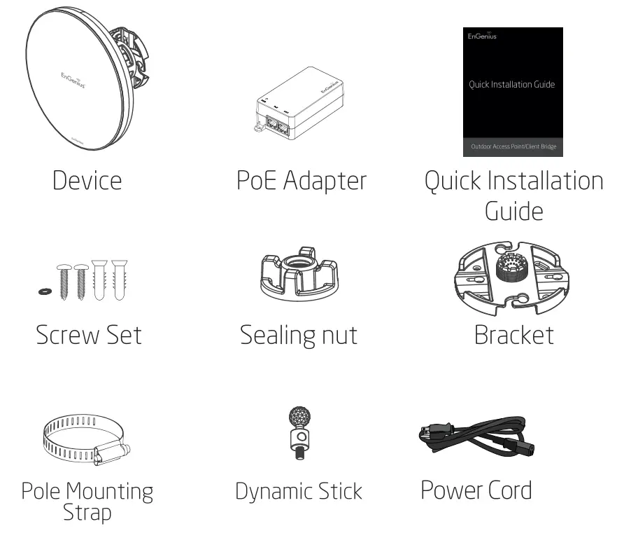
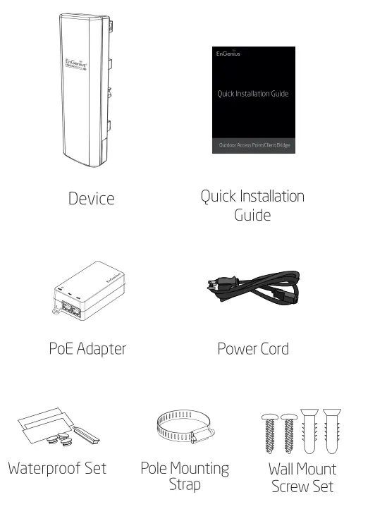
Package Contents
ENS500-AC/ ENSSOOEXT-AC
En Station5-AC/ EnStationAC
Minimum Requirements+ Broadband Internet Service(Cable or DSL Modem)+ Internet Browser(Internet Explorer, Safari, Firefox, Chrome, Edge)
Connecting the device
A) Remove the rear bottom panelB) Connect one end of the Ethernet cable into the LAN(PoE) port of the AP/Bridge and the other end to the PoE Port on the PoE Adapter.C) Connect the Power cord with the PoE Adapter and plug the other end into an electrical outlet.D) Connect the second Ethernet cable into the LAN port of the PoE Adapter and the other end to the Ethernet Port on the computer.E) Place the panel removed from step A back into the device.
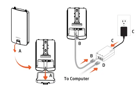
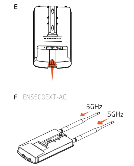
F) Screw on the provided antennas to the top of devices (External Antennas devices only).Note: The device should ONLY be powered via Ethernet cable connected to the included PoE Adapter.
 |
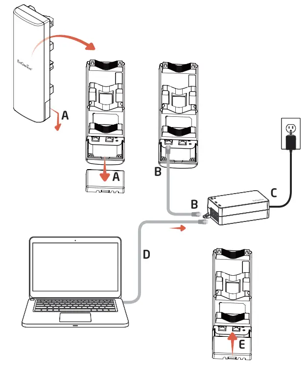 |
A) Remove the rear bottom panel.B) Connect one end of the Ethernet cable into the LAN(PoE) port of the CPE and the other end to the PoE Port on the PoE Adapter.C) Connect the Power cord to the PoE Adapter and plug the other end into an electrical outletD) Connect the second Ethernet cable into the LAN port of the PoE Adapter and the other end to the Ethernet Port onto the computer.E) Place the panel removed from step A back into the device
Note:+ The device should ONLY be powered via Ethernet cable connected to included PoE Adapter. EnStationS-AC / EnStationAC support Proprietary 24V/54 PoE input.+ For En StationAC: The 2nd Ethernet port of the device can supply the 802.3af power source when used with the included PoE Adapter.

IP Address Configuration
A) Once your computer is on, ensure that your TCP/IP is set to On or Enabled. Open Network Connections and then click Local rea Connection.Select Internet Protocol Version 4 (TCP/1Pv4).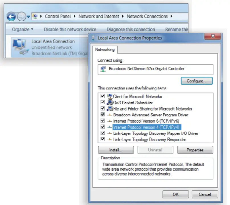 B) If your computer is already on a network, ensure that you have set it to a Static IP Address on the interface. (Example: 192.168.1.10 and the Subnet Mask address as 255.255.255.0.)
Device Setup
A) In the address bar of the web browser, enter 192.168.1. 1 and hit enter. To configure the device open a web browser. B) A login screen will appear. By default, the user name of the device is admin and the password is admin. Enter the current username and password of the device and then click Login.
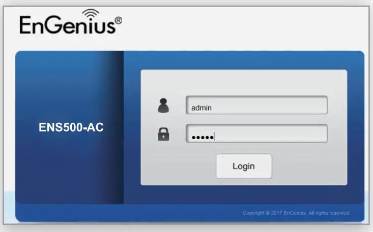 Note: The model name on the login screen depends on the product you are using.C) You can also use the En\WiFi App and connect to the management SSID which is on the device label and GUI to configure the device. The default \Wi-Fi password is 12345678.

Switching Modes
Configure on GUIA) The device can operate in the following modes.Enjoy enabled: Access Point, Client Bridge, WDS AP, WDS Station.Enjoy disabled: Access Point, Client Bridge, WDS AP, WDS Bridge, WDS Station.
Note: The model name on the login screen depends on the product you are using.B) Click on the Wireless link under the Network and set up the Operation Mode.
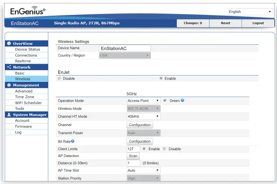
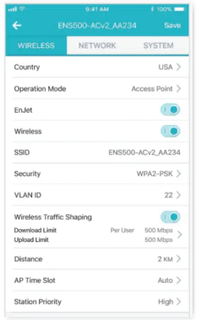
* It may take up to 90 seconds for the device to initially power up.Configure on EnWifi AppC) Usee EnWiFi App open configure→wireless to setup the operationMode.
Mounting the Device
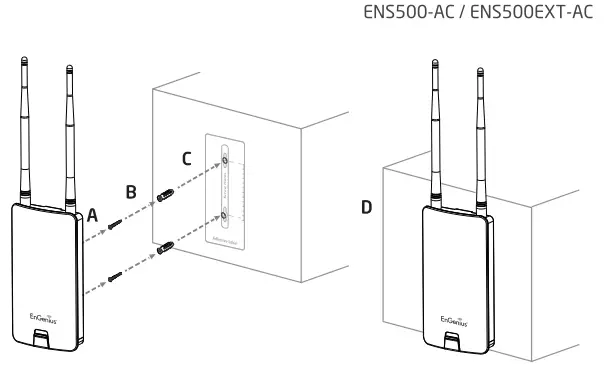
ENSSOO-AC / ENSSOOEXT-AC / ENHSOOWall MountingA) Determine where the Access Point is to be placed and stick the Adhesive label on the surface.B) Use the appropriate drill bit drill to 8.1 mm diagram and 26 mm depth holes on the markings of the label.C) Remove the label and Screw the anchors onto the holes until they are flush with the wall.D) Screw the includes screws into the anchors. place the Access Point against the wall with the mounting screw heads.
 |
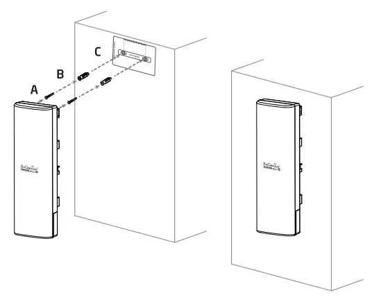 |
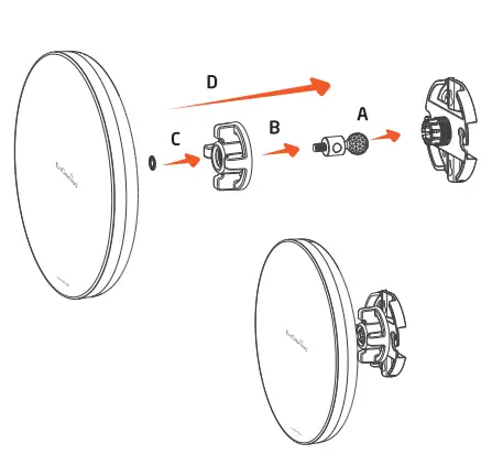
EnStationS-AC / EnStationACA) Plug the dynamic stick into the bracket.B) Screw the sealing nut and assembled parts, tighten it with 80kgf.cm.C) Put the lock washer on the dynamic stack.D) Assemble the mounting parts to the device.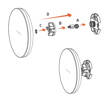 E) Determine the mounting location. Mark and drill two pilot holes aligning to the screw holes of the bracket.F) Put wall anchors into the holes and insert a screw into the wall anchor.G) Screw and secure the bracket in place.
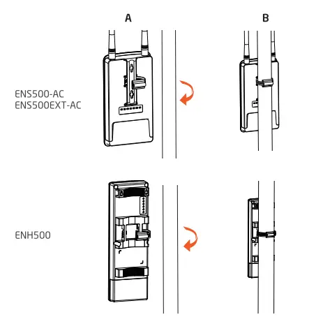
Pole MountingENSSOO-AC / ENSSOOEXT-AC / ENHSOOA) Thread the open end of the Pole Strap through the two tabs on the Pole Mount Bracket.B) Lock and tighten Pole Strap to secure Pole Mount Bracket to the pole.
A) Plug the dynamic stick into the bracket.B) Screw the sealing nut and assembled parts, tighten it with 80kgf.cm.C) Put the lock washer on the dynamic stack.D) Assemble the mounting parts to the device.
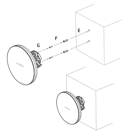
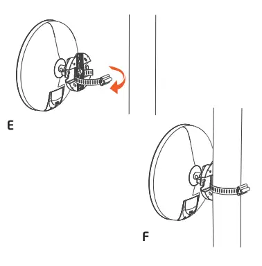
E) Thread the open end of the pole strap through the two tabs on the bracket.F) Lock and tighten the pole strap to secure the bracket to the pole.
Technical Support
| Country of Purchase | Service Center | Service Information |
| North America www.engeniustech.com | Los Angeles, USA | [email protected] Local (+1) 714 432 8668 |
| www.engeniuscanada.com | Canada | [email protected] Local:(+1) 905 940 8181 |
| Europe www.engeniusnetworks.eu | Netherlands | [email protected] Local: (+31) 40 8200 887 |
| Africa/CIS/Middle East www.engenius-me.com | Dubai, UAE | [email protected] Local: (+971)4 357 5599 |
| Asia/Oceania www.engeniustech.com.sg | Singapore | [email protected] Local: (+65) 62271088 |
| Taiwan www.engeniustech.com.tw | Taiwan, R.O.C. | [email protected] Toll Free 0800 003 885 |
Notes
![]() Maximum data rates are based on IEEE 802.11 standards. Actual throughput and range may vary depending on many factors including environmental conditions, the distance between devices, radio interference in the operating environment, and mix of devices in the network. Features and specif cations are subject to change without notice. Trademarks and registered trademarks are the property of their respective owners. For the United States of America: Copyright© 2019 EnGenius Technologies, Inc. All rights reserved.
Maximum data rates are based on IEEE 802.11 standards. Actual throughput and range may vary depending on many factors including environmental conditions, the distance between devices, radio interference in the operating environment, and mix of devices in the network. Features and specif cations are subject to change without notice. Trademarks and registered trademarks are the property of their respective owners. For the United States of America: Copyright© 2019 EnGenius Technologies, Inc. All rights reserved.
[xyz-ips snippet=”download-snippet”]