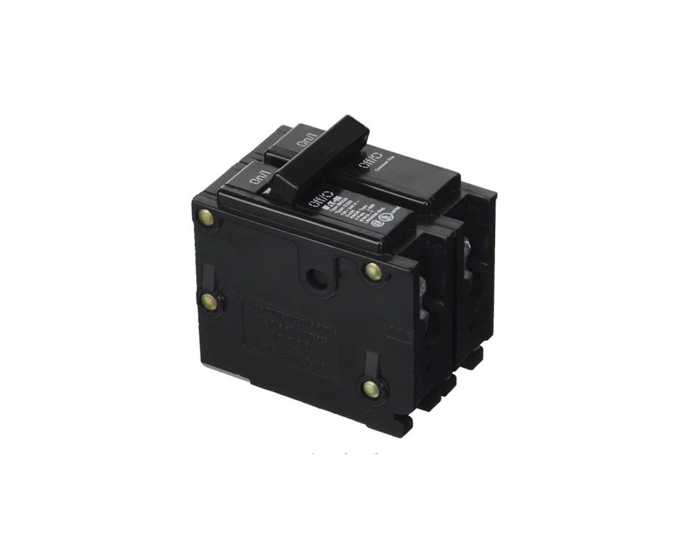
BRK-100A-2P-240V Breakers in the Enphase Enpower Smart Switch Installation Guide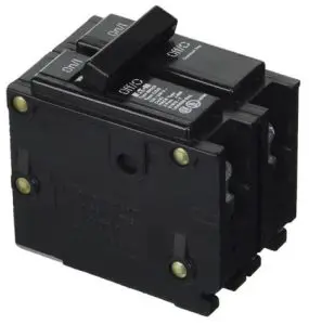
To install Eaton CSR and BR type circuit breakers in the Enphase Enpower™ smart switch , read and follow all warnings and instructions in this guide. If you do not fully understand any of the concepts, terminology, or hazards outlined in these instructions, refer installation to a qualified electrician or installer. These instructions are not meant to be a complete explanation of a renewable energy system. All installations must comply with national and local electrical codes. Professional installation is recommended.
SAFETY
IMPORTANT SAFETY INSTRUCTIONSSAVE THESE INSTRUCTIONS
This guide contains important instructions that you must follow during installation of circuit breakers in the Enphase Enpower smart switch.
DANGER! Risk of electric shock. Always de-energize the Enpower before beginning the following procedure
Safety Instructions
 |
DANGER: Risk of electric shock. Risk of fire. Only qualified electricians should install, troubleshoot, or replace the Enpower. |
|
DANGER: Risk of electric shock. Risk of fire. Do not attempt to repair the Enpower. DO NOT REMOVE THE DEADFRONT — NO SERVICE-
ABLE PARTS. Tampering with or opening the Enpower will void the warranty. If the Enpower fails, contact Enphase Customer Support for assistance at enphase.com/en-us/support/contact. |
|
DANGER: Risk of electric shock. Do not use Enphase equipment in a
manner not specified by the manufacturer. Doing so may cause death or injury to persons, or damage to equipment. |
|
DANGER: Risk of electric shock. Do not install the BRK-20A-2P- 240V-B circuit breaker without first removing AC power from the
photovoltaic system and ensuring that the DC switch on the Enphase Encharge batteries are off. Disconnect the power coming from the photovoltaics and ensure that the DC switch on the Encharge batter- ies are off before servicing or installing. |
|
DANGER: Risk of electric shock. Risk of fire. Do not work alone.
Someone should be in the range of your voice or close enough to come to your aid when you work with or near electrical equipment. |
|
DANGER: Risk of fire. Do not allow or place flammable, sparking, or explosive items near the Enpower. |
|
|
DANGER: Risk of electric shock. In areas where flooding is possible, install the Enpower at a height that prevents water ingress. |
 |
WARNING: Before installing or using the circuit breaker kits, read all instructions and cautionary markings in this guide and on the
equipment. |
|
WARNING: Do not install or use the circuit breaker kit if it has been damaged in any way. |
Safety and Advisory Symbols
|
DANGER: This indicates a hazardous situation, which if not avoided, will result in death or serious injury. |
|
WARNING: This indicates a situation where failure to follow instructions may be a safety hazard or cause equipment malfunction. Use extreme caution and follow instructions carefully. |
| ✓ | NOTE: This indicates information particularly important for optimal system operation. Follow instructions carefully. |
|
WARNING: Do not sit on, step on, place objects on, or insert objects into the Enpower. |
|
WARNING: Do not place beverages or liquid containers on top of the Enpower. Do not expose the Enpower to liquids or flooding. |
|
✓ |
NOTE: Perform installation and wiring, including protection against lightning and resulting voltage surge, in accordance with all applicable
local electrical codes and standards. |
|
✓ |
NOTE: Because Encharge is grid forming, you must install signage in accordance with NEC articles 705, 706, and 710. |
|
✓ |
NOTE: Using unapproved attachments or accessories could result in damage or injury. |
|
✓ |
NOTE: Install properly rated over current protection as part of the system installation. |
|
✓ |
NOTE: To ensure optimal reliability and to meet warranty require- ments, the BRK-20A-2P-240V-B circuit breaker must be installed and/or stored according to the instructions in this guide. |
|
✓ |
NOTE: While Enpower provides capability for connection of a generator, it does not presently support use with generators. Do not attempt to connect a generator until Enpower is ready to support a generator. This functionality is reserved for future use and will require an upgrade process to be followed by a qualified electrician. |
| 1 | NOTE: While Enpower provides capability for connection of a genera- tor, it does not presently support use with generators. Do not attempt to connect a generator until Enpower is ready to support a genera- tor. This functionality is reserved for future use and will require an upgrade process to be followed by a qualified electrician. |
![]() DANGER! Risk of electric shock. Always de-energize the Enpower before beginning the following procedure.
DANGER! Risk of electric shock. Always de-energize the Enpower before beginning the following procedure.
Install Breakers as Needed
The Enpower includes one two-pole 40A circuit breaker that feeds the neutral forming transformer (NFT). You can install additional breakers, if needed. You must follow all NEC and local electrical codes.
Install breakers as needed for the AC grid, main load, Enphase IQ Combiner, Enphase Encharge batteries, and generator (reserved for future use). These breakers are not included and must be ordered separately.
NOTE: You must install a backup loads breaker if required by local code.
NOTE: Generator connection is not currently supported. This feature will be supported in future after an over-the-air software upgrade.
WARNING! Risk of injury and equipment damage. Use only the breakers listed in the following table. Allowed breaker types include:
| Enphase Model No. | Type and Eaton part no. |
| BRK-100A-2P-240V
BRK-125A-2P-240V BRK-150A-2P-240V BRK-175A-2P-240V BRK-200A-2P-240V BRK-20A-2P-240V-B BRK-30A-2P-240V BRK-40A-2P-240V BRK-60A-2P-240V BRK-80A-2P-240V |
• Main Breaker, 2 pole, 100A, 25kAIC, CSR2100N or CSR2100
• Main Breaker, 2 pole, 125A, 25kAIC, CSR2125N • Main Breaker, 2 pole, 150A, 25kAIC, CSR2150N • Main Breaker, 2 pole, 175A, 25kAIC, CSR2175N • Main Breaker, 2 pole, 200A, 25kAIC, CSR2200N • Circuit Breaker, 2 pole, 20A, 10kAIC, BR220B • Circuit Breaker, 2 pole, 30A, 10kAIC, BR230B • Circuit Breaker, 2 pole, 40A, 10kAIC, BR240B • Circuit Breaker, 2 pole, 60A, 10kAIC, BR260 • Circuit Breaker, 2 pole, 80A, 10kAIC, BR280 |
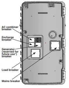
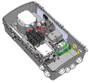
Breaker installation positions are noted in the diagram:
- A ) Ensure that the Enpower is completely de-energized.
- B ) Open the three latches that lock the enclosure door. To release the latch, pull the latch handle forward and then to the right. With all the latches opened, swing open the enclosure door.WARNING: Risk of equipment damage. Do not remove the pre-installed solar shield attached to the enclosure door.
- C ) Use a Phillips screw driver to loosen the six screws along the periphery of the deadfront. Support the deadfront to keep it from falling while performing the next step.
- D ) While supporting the deadfront, use a screwdriver to disconnect the deadfront ground wire from the grounding bar before the dead front isremoved.
- E ) Use the two tabs on the front to assist handling the deadfront during the removal. Keep the deadfront and screws handy as you will need them later.WARNING: Risk of electric shock. To maintain the warranty, do not modify the deadfront other than to remove or replace filler plates, as needed.
- F ) If you install a main breaker or load breaker, remove the standard lugs before installing the Eaton CSR breaker. By default, lugs are provided in the Enpower unit for connection to the mains and to the load. In case of usage without breakers, the conductors are connected directly to these lugs. When breakers are used, the lugs are replaced with breakers during installation.
- G ) Remove a filler plate from the deadfront for each breaker position you will use. Refer to the breaker position diagram to the left. To remove the filler plate, press the two snaps inward while gently pushing the filler plate out.
- H ) For the Encharge, AC Combiner or Generator (reserved for future use) connection, snap the appropriately sized BR series two-pole Eaton breaker onto the busbar, using only the breaker positions indicated in the diagram on the door of the unit. Breaker functional position are not interchangeable with one another. The wires to be connected to each breaker are located beside each breaker position. Remove the heatshrink cap on the wire ends before inserting into the breaker.
- I ) Install each breaker by rocking it to the left, catching the clips that hold it in place. Then rock the breaker to the right so it is fully seated and secure.
- J ) For the main load breaker, use an appropriately sized CSR Eaton breaker. Install at the location indicated in the diagram on the door of the unit.
- K ) Remove the mains/load lugs by unscrewing the two nuts holding the lugs. Re-use the same nuts to fix the CSR breakers in the same position.
- L ) Use the M4 screw (from the lit kit marked 150-00148 that ships with the Enpower) to secure the mains breaker (not the load breaker). Use a T20 drive to tighten the M4 screw to 1.5 N•m (13.3 lb•in). Do not use any other screw.
- M ) Check that all breakers are properly seated.
- N ) Torque the breaker connections as listed in the following and in the conductor table on the unit.
- L ) Purchase and install an Eaton type BR circuit breaker hold-down screw kit (model BRHDK125) to secure only the Encharge and generator (reserved for future use) double-pole circuit breaker(s). Refer tohttps://www. homedepot.com/p/Eaton-Type-BR-Hold-Down-Bolting-Screw-Kit-BRHDK125/100193360 for installation information and specifications.
Required practices when torquing connections:
- Always follow NEC 2017 110.4 (D) dictates.
- Use a calibrated torque tool to achieve the indicated torque values.
- Use tamper-proof torque mark/paint after torquing connections.
Lugs at main load breaker position
Breakers installed at main load position
 report this ad
| Connections | Wire size (AWG) | Torque (N•m / lb•in) |
| CSR breakers | Cu/AL: 300 KCMIL – 2 | 28.2 / 250 |
| BR breakers (wire provided) | 6 | 3.1 / 27 |
References
[xyz-ips snippet=”download-snippet”]