![]()
QUICK INSTALL GUIDE(Models ENCHARGE-3-1P-NA and ENCHARGE-10-1P-NA)Install the Enphase Encharge Storage System
To install the Enphase Encharge 3TM storage system or Encharge 10™ storage system and the Enphase wall-mount bracket, read and follow all warnings and instructions in this guide. Safety warnings are listed on the back of this guide. These instructions are not meant to be a complete explanation of how to design and install an energy storage system. All installations must comply with national and local electrical codes and standards. Only qualified electricians shall install, troubleshoot, or replace the Encharge 3 or Encharge 10.
The EnchargeTM storage system includes the Enphase Encharge Battery(ies) with integrated Enphase IQTM Microinverters. The Enphase IQ EnvoyTM communication gateway measures PV production and home energy consumption. The Encharge storage system senses when it is optimal to charge or discharge the battery so that energy is stored when it is abundant and used when scarce. Encharge storage systems are capable of providing backup power when an Enphase Enpower™ smart switch is installed at the site.Five unique installation scenarios are shown:
Whole home backup with Enpower as service entrance and PV combiner connected to Enpower. This is the preferred configuration for back up of the entire main load panel. This configuration supports up to an 80A breaker for the PV circuit and an 80A breaker for battery storage.NOTE:
- For M215/M250 connection to Ensemble, refer tech brief at https://enphase.com/en-us/storage-m-series
- M series microinverters require Envoy-S metered.

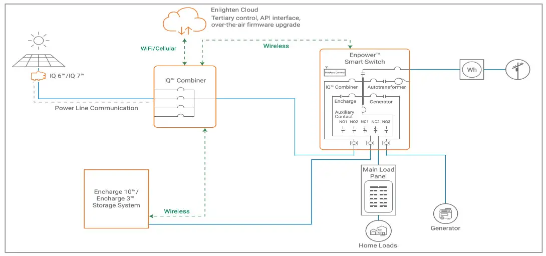
Whole home backup with Enpower as service entrance and PV combiner connected to main load panel. This is the preferred configuration when you back up the entire main load panel, and the size of the PV combiner circuit is more than 80A. In this configuration, the PV combiner circuit connection space in Enpower is left vacant. When existing PV combiner circuits are connected to the main load panel, and you want to add battery storage to the system, you can keep the PV combiner connected to the main load panel and connect only the battery storage system to Enpower.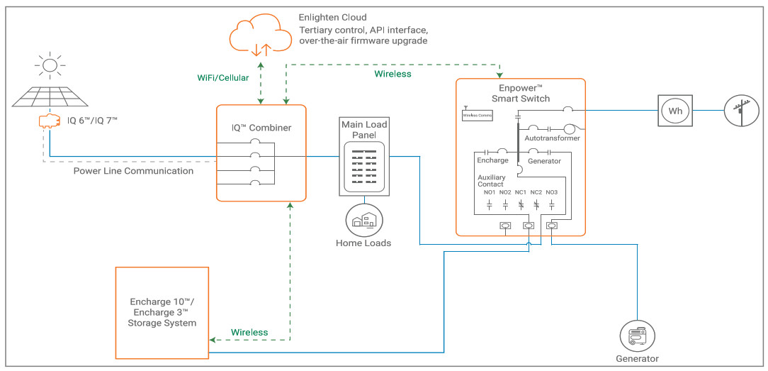
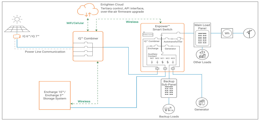
Partial home backup with main load panel as service entrance and PV combiner connected to Enpower. When PV circuits breaker size is less than 80A, this is the preferred configuration for partial home backup with subpanel.
© 2021 Enphase Energy. All rights reserved. Enphase, the Enphase logo, Enpower smart switch, Encharge storage system, IQ Envoy, IQ combiner, IQ microinverter, Installer Toolkit, Enlighten and other trademarks or service names are trademarks of Enphase Energy, Inc. Data subject to change. 2021-04-22
Partial home backup with main load panel as service entrance and PV combiner connected to subpanel. This is the preferred connectionconfiguration for partial home backup using a subpanel when the PV circuit breaker size is more than 80A. The space available in Enpower for combiner (solar) connection is left vacant.
Self consumption, no Enpower smart switch. The preferred configuration when adding battery storage and PV for self-consumption in a grid-tied application with no option for backup during outages. PV and Encharge will not operate when the grid is unavailable.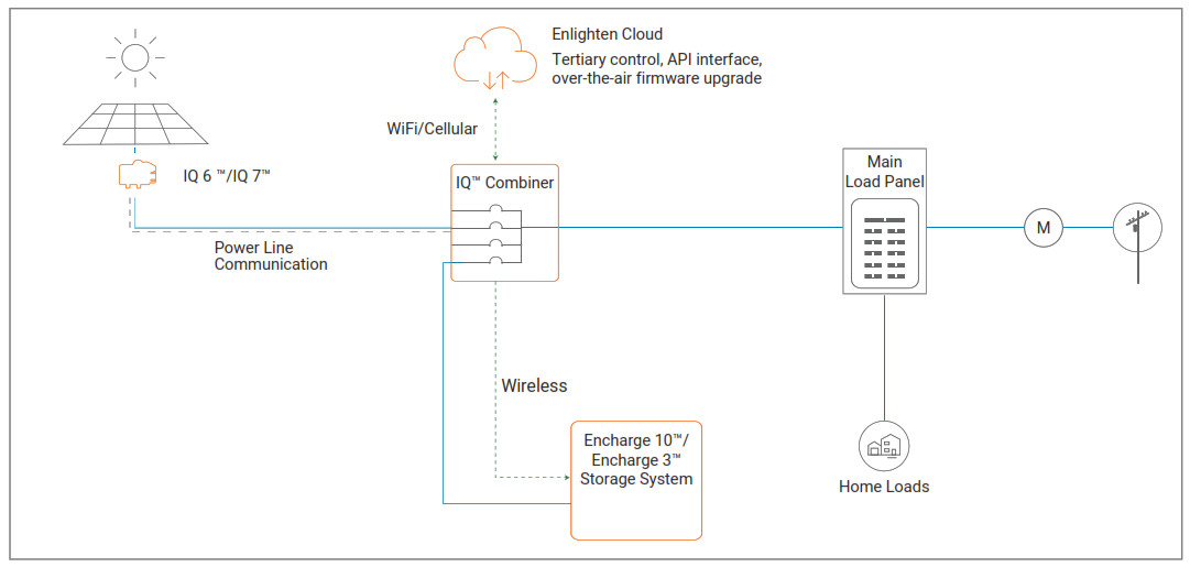
PREPARATION
A ) Inspect the packaging and the Encharge Battery(ies) for damage, such as cracks, dents, or leaking electrolyte. Do not install or use the Encharge Battery(ies) if it has been damaged in any way. If damaged, contact your distributor for replacement.B ) Ensure that your kit includes the following Encharge components:
- The Encharge 10 includes three batteries and two inter-unit raceways, an Encharge 10 triple-width cover, and a triple-width mounting bracket.
- The Encharge 3 includes one battery, and single-width cover with mounting bracket.NOTE: Check the “Energize By” label on the shipping box to verify that the Encharge Battery(ies) will be installed by the date shown. If the date has passed, contact your distributor for next steps.WARNING: Risk of injury. Take care when lifting. The Encharge Battery unit is heavy (44.2 kg/ 97.4 lbs) and requires two persons to lift.
C ) Ensure you have the following required Enphase items for backup systems:
- An Enphase Enpower smart switch with microgrid interconnect device (MID) functionality and an Enphase IQTM Combiner.
- The Enphase Encharge system requires an Internet connection through the IQ Envoy in the IQ Combiner. Failure to maintain an Internet connection may have an impact on the warranty. See enphase.com/warranty for full terms.
- Wireless communications kit (COMMS-KIT-01) to be installed at the IQ Envoy for communications with Encharge and Enpower. Includes USB cable for connection to IQ Envoy / IQ Combiner and allows wireless communication with Encharge and Enpower.
- Encharge lifting handles two pieces (ENCHARGE-HNDL-R1).
D ) Make sure you also have the following required items:
- Mounting location that is structurally suited to bearing the weight of the Encharge Battery(ies). Total weight for the Encharge 3, including the Encharge base unit, cover and wall mount bracket, is 52 kg (114.6 lbs). Total weight for the Encharge 10, including the three Encharge base units, cover, and wall mount bracket, is 154.7 kg (341 lbs). The wall must contain blocked studs that can bear the battery weight or can be of masonry or other suitable structure.
- Tools: conduit (with fittings and fitting tools), drill, 5/32 inch pilot bit (or metric equivalent), screwdriver, socket wrench, torque wrench, level, wire stripper, and stud finder if installing on studs.
- Fasteners for wall mount bracket. Slots are 6.8mm (0.27″). Check with a structural engineer and local standards for requirements: Single-wide bracket: Three 1/4″ lag bolts or screws, 7.6 cm (3 inches) long (depending on attachment wall). Triple-wide bracket: Nine 1/4″ lag bolts or screws, 7.6 cm (3 inches) long (depending on attachment wall).
- Washers for use between fastener heads and wall-mount bracket.
- Copper conductors: No. 14 – 8 AWG (11mm/7/16 inch strip length) copper conductors (rated at 75° C or 90° C) for terminals.
- Conduit fittings: 3/4 inch (left side) and 1/2 inch (right side) hubs are required for all installations, and NEMA Type 3R conduit fittings (hubs) are needed when installing out of doors (one for each used conduit opening). Also needed are conduit plugs to close unused conduit openings and conduit grounding nuts.
- Over current protection: The overcurrent protection in Encharge is not branch circuit overcurrent protection and cannot be relied upon for that purpose. The branch circuit overcurrent protection is located in Enpower or, when combining , in a separate combiner. See the Enphase Enpower Quick Install Guide for more information.
- Personal protective equipment (PPE) for handling lithium batteries as required by local safety standards.
E ) Verify that main service is 120/240 VAC, and not 208/120 VAC. Encharge batteries cannot be installed where L1 to L2 measures 208 VAC.F ) Install the PV system and the IQ Combiner as directed by the Enphase installation manuals.
INSTALLATION
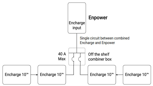
- Plan a location for the Encharge batteriesThe Encharge housing is NEMA type 3R and can be installed indoors or outdoors. The terminal blocks accepts copper conductors of No. 14 – 8 AWG.A ) Following local standards, choose a well-ventilated location where the ambient temperature and humidity are within -15° C to 55° C (5° F to 131° F) and 5% to 100% RH, non-condensing, preferably out of direct sunlight. The optimum ambient temperature range for installation location is 0º C to 30º C (32º F to 86º F).B ) Ensure that the mounting location can sustain the total weight of the Encharge batteries and mounting bracket. Total weight for the Encharge 3, including the Encharge base unit, cover and wall mount bracket, is 52 kg (114.6 lbs). Total weight for the Encharge 10, including the three Encharge base units, cover, and wall mount bracket, is 154.7 kg (341 lbs). WARNING: The installer should install blocking between studs to ensure that no single stud carries the entire weight load of the Encharge batteries.C ) Plan the mounting location to be at least 15cm (six inches) off the ground and 15cm (six inches) from the ceiling. Keep the Encharge away from falling or moving objects, including motor vehicles. WARNING: If mounted in the path of a motor vehicle, we recommend a mounting height that is 91 cm (36-inch) minimum above the floor.D ) Ensure that there are no pipes or electrical wires where you plan to drill.E ) Plan to maintain at least three feet of clearance in front of each Encharge. Allow at least 15cm (six inches) clearance on top and bottom of the Encharge so that the vents on the top and bottom of the units are not blocked for air circulation.F ) Consider the dimensions of the Encharge batteries, easy access, height, and length of cable when selecting the location.G ) Select a location where you can interconnect to the Enphase Enpower smart switch.H ) Follow all local standards.J ) Review your external conduit plan to determine to which side of the field wiring compartment you will connect conduit.K ) Up to two Encharge 10 (or six Encharge 3) units can be daisy chained on a single branch circuit. For installations with more than this number of units, there must be a separate load center, subpanel, or circuit combiner with over current protection to combine the daisy chained circuits, and you must run only one circuit for all the Encharge units to the Enpower (or to Enphase IQ Combiner for grid-tied-only installations). You must select proper conductors and circuit breakers for these circuits according to local codes, standards, and other applicable requirements. Enpower supports up to a maximum of 80 A breaker for Encharge connection circuit.The subpanel could be a small, two circuit box with circuit breakers. The circuit breakers in the box would have to be suitable for back-feeding, per NEC 408.36(D).Select the right size subpanel and breakers based on the number of Encharge units being installed. Up to four Encharge 10s or twelve Encharge 3s can be safely connected to 80A load center.To do this, you must purchase an off-the-shelf subpanel and install as shown in the following image:
- Install the AC disconnectFollowing all local codes and standards:A ) Install an AC disconnect that can break the maximum rated current of the branch circuit under load. The AC disconnect must be readily accessible and located within line-of-sight of Encharge, per NEC 2017 706.7(A).B ) Each Encharge unit is suitable for use with up to No. 8 AWG wires on a maximum 40 A branch circuit. If more than 32 A of Encharge batteries (corresponding to a 40 A branch circuit) are installed, a separate subpanel must be installed between the Encharge units and Enpower to combine the Enpower circuits together. All circuit breakers in the subpanel must be suitable for back-feeding, per NEC 408.36(D).C ) Verify that AC voltage at the site is within range: single-phase L1 to L2 voltage must measure between 211 and 264 VAC, while L-N should measure between 106 and 132 VAC.
- Prepare to install the wall-mount bracketA ) Make sure that the planned position for the wall-mount bracket meets clearance requirements as shown. The image depicts a single bracket, but clearances and requirements are the same for the triple-width bracket.B) Ensure that the mounting location can sustan the weight of the Encharge batteries and mounting bracket. Total weight for the Encharge 3 including the mounting brackets and cover is 52 kg (114.6 lbs), while the total weight for Encharge 10 including the mounting bracket and cover add up to 154.7 kg (341 lbs).C ) Starting at installation position closest to the power source, mark a level line on the wall as a guide. WARNING! Multiple risks. Make sure not to drill or attach into electric wiring or pipes that are in the wall!Mounting Surface Flatness (Across the Installation width and height) recommended to be within 2mm*NOTE: The above specified surface flatness requirment is applicable to all the combinations of Encharge 3 and 10.* If the difference in flatness is more than 2mm, recommend installing a substructure like unistrut for better alignment of the units.
- Install the Encharge 3 (single width) or Encharge 10 (triple width) wall mount bracketFollow the instruction below for the bracket style (single-width or triple-width) you are installing. WARNING! Risk of injury and equipment damage. Attach the wall mount to the wall so that it is no more than five percent from vertical. See the following image for reference:Allowable tilt from vertical for Encharge installationEncharge 3 — single-width bracketA ) Place the wall-mount bracket on the wall so that the mounting holes in the middle of the bracket align with the center of the stud.B ) Use a level to keep the bottom of the wall-mount bracket level.C ) Use 1/4″ screws (or masonry attachments for masonry) to attach the bracket using one screw and washer for each slot (6.8mm / 0.27″).Tighten all the screws to manufacturer’s specified torque values.D ) Verify that the wall-mount bracket is solidly attached to the wall. You must use four screws in each mounting bracket. WARNING! Risk of injury and equipment damage. Do not mount an Encharge 3 on a bracket that is not properly mounted.E ) If installing additional batteries, install adjacent wall-mount brackets, as needed. Be sure to align the mounting holes in the wall-mount bracket to the center of the wall stud. You may install another row of brackets above the one already installed. Maintain at least 15 cm (six inches) vertical clearance between rows of Encharge installations, and ensure that the wall can support the structural load (weight) of the installation. WARNING! Risk of injury and equipment damage. Do not install more than three Encharge 3 units per 20A branch circuit.Encharge 3 wall mount bracketEncharge 10 — triple-width bracketA ) Place the wall-mount bracket on the wall so that the mounting holes in the middle of the bracket align with the center of the stud, and the mounting holes on the left and right align with the adjacent studs.B ) Use a level to keep the bottom of the wall-mount bracket level.C ) Use 1/4″ screws (or masonry attachments for masonry) to attach the bracket using one screw and washer for each slot (6.8mm / 0.27″). Use screws in each section of the mounting bracket to support the three Encharge battery units. There is an array of slots so that you can choose those that allow you to mount the bracket on studs. Tighten all the screws to manufacturer’s specified torque values.D ) Verify that the wall-mount bracket is solidly attached to the wall. WARNING! Risk of injury and equipment damage. Do not mount Encharge 10 batteries on a bracket that is not properly mounted.E ) If installing additional batteries, install adjacent wall-mount brackets, as needed. Be sure to align the mounting holes in the wall-mount bracket to the center of the wall stud. You may install another row of brackets above the one already installed. Maintain at least 15 cm (six inches) vertical clearance between rows of Encharge installations, and ensure that the wall can support the structural load (weight) of the installation. WARNING! Risk of injury and equipment damage. Do not install more than one Encharge 10 unit per 20A branch circuit.Encharge 10 wall mount bracket
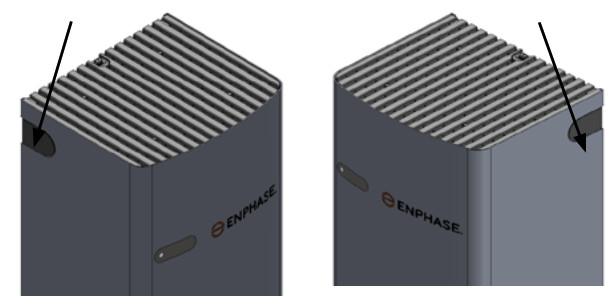
- Mount the Encharge Battery(ies) on the wall WARNING: Risk of injury. Take care when lifting.Each Encharge battery base unit is heavy (44.2 kg/ 97 lbs) and requires two persons to lift. WARNING! Risk of injury and equipment damage. Avoid dropping the Encharge Battery(ies). Doing so may create a hazard, cause serious injury, and/or damage the equipment. WARNING! Risk of injury and equipment damage. Protect theEncharge Battery(ies) from impact damage and improper use.A ) Two person together must lift a single Encharge battery base unit from the packaging and place it right side up on a flat surface.B ) Locate the Encharge lifting handles:C ) If installing multiple battery units, plan to install the Encharge battery unit located closest to the main supply.D ) The first person lifting must slide the longer front handle under the front edge of the Encharge battery, then tilt the handle up so that handle tabs engage with the slots on the front side of the battery.E ) The second person lifting must slide the shorter side handle under the left or right side (as needed) of the Encharge battery, and support the upper back of the Encharge battery with their free hand.F ) Together, lift the Encharge battery and bring it to the already mounted bracket.G ) Hold the Encharge battery at an angle so the top of the unit sets into the top of the wall-mount bracket. WARNING! Risk of injury and equipment damage. Do not release the Encharge battery unit until you ensure that the Encharge battery unit is fully seated in the wall-mount bracket shelf.H ) Once the top of the battery is engaged with the top tabs of the wall-mount bracket, keep the battery vertical, make sure the battery is flush against the bracket, and lower the battery down until fully seated with the wall-mount bracket and set into the bracket shelf.I ) Remove the handles and reserve for the next Encharge battery installation.J ) Use a Phillips screw driver to loosen the screws securing the field wiring compartment cover and remove the cover. Keep the cover and screws handy as you will need them later.K ) Attach the battery to the mounting bracket aligning the screw hole at the top of the battery with the screw hole at the top of the bracket.L ) To record the installation of each Encharge battery base unit, scan the serial number label using Enphase Installer ToolkitTM and your mobile device.
- Install conduit and field wiring DANGER! Risk of electric shock. The DC switch must be in the Locked position before performing this step.A ) If not already done, use a Phillips screw driver to loosen the screws securing the field wiring compartment cover and remove the cover. Keep the cover and screws handy as you will need them later.B ) Remove the sealing plug for entry into the field wiring compartment. If installing only one battery or when installing the last battery in the array, seal up the hole with the supplied sealing plug.C ) Size the conductors (Lines and Ground) to account for voltage rise and to conform to the tables below. Design for a voltage rise total of less than 2%. Encharge can use any circuit breaker size between 10 A and 40 A. Breaker rating and wire size are installation dependent.
Number of Encharge E3/E1 0 units Current (A) Minimum wire size (AWG) Breaker rating (A) 1*E3 5. 14 10 2*E3 11. 14 15 3*E3 or l*E10 16.0 12 20 4*E3 or (1*E 1 0 + 1*E3) 21. 10 30 5*E3 or (1 *E1 0 + 2*E3) 28. 8 35 6*E3 or 2*E10 or (1*E1 0 + 3*E3) 32.0 8 40 *E3 refers to Encharge 3*E10 refers to Encharge 10In all cases in the table, it is possible to always use larger conductors and a breaker sized for that conductor or smaller. For Example in row 3, with 3*E3 or 1*E10, it is possible to use:a) 12 AWG wire with 20 A breaker, orb) 10 AWG wire with 20 A or 30 A breaker, orc) 8 AWG wire with 30, 35, or 40 A breaker
DANGER! Risk of electric shock. Check that the dedicated circuit breaker protecting the branch where the Encharge Battery(ies) will be connected is turned off before wiring. WARNING! Risk of equipment damage. The DC switch must be OFF before installing, otherwise Encharge will try to form a grid.D ) If installing an Encharge 10, install the inter-unit raceways. The left-side and right-side conduit openings are different diameters, so you must install the raceway in the proper direction.• Face the fronts of the batteries, and insert the raceway through the right-hand unit’s left-side conduit opening from within the field wiring compartment, with the arm of the raceway pointing up.• Push the raceway through the right-hand unit’s left-side conduit opening and into the left-side unit’s right-side conduit, opening until the two snap features on the raceway engage the left-side unit’s enclosure.• Once fully inserted, rotate the “arm” toward you until it stops.• The left-side conduit opening of each battery unit has a flat surface, without additional features. The larger seal (green) on the raceway mates with this opening. The right-side conduit opening has a groove around the hole to fit the O-ring (red) of the raceway. Make sure that the O-ring is captured in the groove between the Encharge enclosure and the raceway flange adjacent to the O-ring.E ) Using the conductors and suitable conduits, connect the AC disconnect and the first adjacent Encharge Battery. Use the conduit openings provided to connect the conduit and pass the wires through them. Note that if an Enphase Enpower is in line-of-sight, the breaker can service as a disconnect. WARNING! Risk of equipment damage. Do not modify or rewire the pre-installed wiring or bonding connections in the field wiring compartment. WARNING! Risk of equipment damage. Always connect to two Lines (active) and one ground.F ) Connect each wire in the field wiring compartment to its corresponding conductor (Lines and Ground). Each terminal accepts two 14-8 AWG conductors (11mm/7/16 inch strip length). Tighten to 14 lb-in.G ) If installing an Encharge 10, route the wires from the first Encharge Battery to the adjacent Encharge Battery through the inter-unit raceway. There are two positions for each line and for ground in the terminal block to allow for daisy-chaining. WARNING! Risk of equipment damage. Do not daisy chain more than six total Encharge 3 or two Encharge 10 on a single branch circuit.H ) After all wires in the field wiring compartment are connected and secured, check that there are no exposed conductors.I ) If connecting additional Encharge Batteries, use another conduit and another set of wires to connect between field wiring compartments.J ) Gently arrange all the wires and connectors inside the field wiring compartment.K ) Plug any unused conduit openings before proceeding.L ) Replace the field wiring compartment cover. Use a cross-head screw driver to tighten the cover screws to 2.3Nn (20.3 Ib-in). WARNING! Risk of equipment damage. Ensure that no wires are pinched before replacing the cover. DANGER! Risk of electric shock. The system is not ready to be energized! Do not close the circuit breaker or turn on the DC switch. - Dismounting of Encharge 3 CoverA) Remove the conduit covers from either sides of the Encharge coverB) Lift up the ring of the quarter turn screw.C) Turn the ring in the anticlockwise direction to unlock the screw.D) After unlocking, hold the ring of the screw and lift the top cover up slightly and pull it away from the wall in the indicated direction.E) While pulling out the cover, make sure that the indicated snaps at the bottom of the unit are being unlocked.F) Simillarly for dismounting the Encharge 10 Cover, please follow the instructions from A to E.
- Cover and energize the system WARNING: Before energizing, make sure that ALL Encharge Batteries in the system are properly installed and conductors terminated.NOTE: Check the box for updates on cover installation instructions.A ) Check that the field wiring compartment cover(s) for all Encharge Batteries in the system are closed and secured. WARNING: Complete the Enphase Enpower and Enphase Combiner installations before turning the DC switch(es) ON. DANGER: Risk of electric shock. Before continuing, check that Encharge units are properly wired, and ground connection does not have a L1 or L2 connection, as this introduces a safety hazard.• Apply AC power to the Encharge circuits. Do NOT turn on the DC switch on Encharges.• Using a voltmeter measure the Encharge chassis metal to ground (e.g., grounded conduit) and ensure there is no AC voltage source present. If wiring is incorrect, a ground fault may exist, and the AC voltage may read ~120VAC. If voltage is present, DO NOT touch the chassis, and immediately remove AC power from the Encharge circuits.• Remove AC power to the Encharge circuits and correct the wiring. WARNING! Risk of electric shock and equipment damage. If the DC switch is ON, AC voltage might be present at the terminals. DANGER: Risk of electric shock. AC voltage might be present at the output when the DC switch is on. WARNING: Branch circuit protection must be off before switchingB ) Turn on the DC switches for the Encharge Batteries.NOTE: Do NOT leave the Encharge unit’s DC switch in the ON position for any extended period of time (such as overnight or for more than 24 hours) unless Encharge is commissioned (communicating with Envoy), connected to AC, and has passed functional testing and is operational. Leaving the DC switch ON without AC connection and communication with the system will drain the battery and may cause damage to the battery cells such that they no longer be able to charge. Damage resulting from this improper installation and misuse is not covered under the product’s limited warranty.C ) Place enclosure cover(s) over the battery(ies) as follows.Encharge 3 (single-width battery cover)• Pick up the Encharge 3 Battery cover, stand in front of the battery so that the cover and battery are on a level, and slide the cover over the battery so that the interior guides of the cover slide easily over the guides on the battery unit.• Check that the screw hole on top of the battery cover aligns with that on the battery.• Use the included screw to attach the cover to the battery. Tighten the screw as needed.Encharge 10 (triple-width battery cover) • The Encharge 10 Battery cover in wide and may require two persons to guide smoothly over the battery units.• Pick up the Encharge 10 Battery cover, stand in front of the battery so that the cover and battery are on a level, and slide the cover over the battery so that the interior guides of the cover slide easily over the guides on the battery units.• Check that the screw holes on top of the battery cover align with those on the batteries.• Use the included screws to attach the cover to the batteries. Tighten the screws as needed.Encharge 10 without coverD ) Turn on the AC circuit feeding the Encharge Battery(ies).E ) The Encharge battery LED(s) flashes blue for the duration of the startup process and then start flashing green until the startup process is complete. If the LED(s) is not flashing blue and then green, see the following troubleshooting section and Enphase Ensemble Troubleshooting Guide.

 Encharge 3 — single-width bracketA ) Place the wall-mount bracket on the wall so that the mounting holes in the middle of the bracket align with the center of the stud.B ) Use a level to keep the bottom of the wall-mount bracket level.C ) Use 1/4″ screws (or masonry attachments for masonry) to attach the bracket using one screw and washer for each slot (6.8mm / 0.27″).Tighten all the screws to manufacturer’s specified torque values.D ) Verify that the wall-mount bracket is solidly attached to the wall. You must use four screws in each mounting bracket.
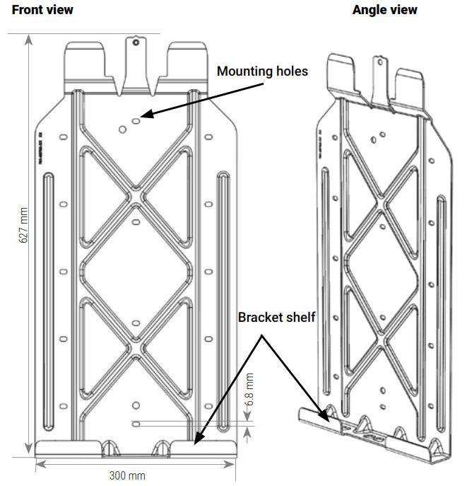 Encharge 10 — triple-width bracketA ) Place the wall-mount bracket on the wall so that the mounting holes in the middle of the bracket align with the center of the stud, and the mounting holes on the left and right align with the adjacent studs.B ) Use a level to keep the bottom of the wall-mount bracket level.C ) Use 1/4″ screws (or masonry attachments for masonry) to attach the bracket using one screw and washer for each slot (6.8mm / 0.27″). Use screws in each section of the mounting bracket to support the three Encharge battery units. There is an array of slots so that you can choose those that allow you to mount the bracket on studs. Tighten all the screws to manufacturer’s specified torque values.D ) Verify that the wall-mount bracket is solidly attached to the wall.
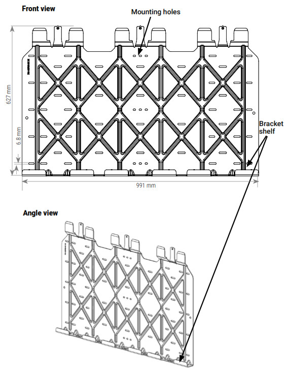
 C ) If installing multiple battery units, plan to install the Encharge battery unit located closest to the main supply.D ) The first person lifting must slide the longer front handle under the front edge of the Encharge battery, then tilt the handle up so that handle tabs engage with the slots on the front side of the battery.E ) The second person lifting must slide the shorter side handle under the left or right side (as needed) of the Encharge battery, and support the upper back of the Encharge battery with their free hand.F ) Together, lift the Encharge battery and bring it to the already mounted bracket.G ) Hold the Encharge battery at an angle so the top of the unit sets into the top of the wall-mount bracket.
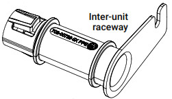 • Push the raceway through the right-hand unit’s left-side conduit opening and into the left-side unit’s right-side conduit, opening until the two snap features on the raceway engage the left-side unit’s enclosure.• Once fully inserted, rotate the “arm” toward you until it stops.• The left-side conduit opening of each battery unit has a flat surface, without additional features. The larger seal (green) on the raceway mates with this opening. The right-side conduit opening has a groove around the hole to fit the O-ring (red) of the raceway. Make sure that the O-ring is captured in the groove between the Encharge enclosure and the raceway flange adjacent to the O-ring.E ) Using the conductors and suitable conduits, connect the AC disconnect and the first adjacent Encharge Battery. Use the conduit openings provided to connect the conduit and pass the wires through them. Note that if an Enphase Enpower is in line-of-sight, the breaker can service as a disconnect.
 K ) Plug any unused conduit openings before proceeding.L ) Replace the field wiring compartment cover. Use a cross-head screw driver to tighten the cover screws to 2.3Nn (20.3 Ib-in).
 B) Lift up the ring of the quarter turn screw.
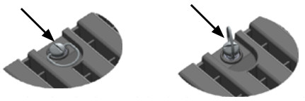 C) Turn the ring in the anticlockwise direction to unlock the screw.
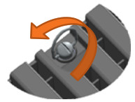 D) After unlocking, hold the ring of the screw and lift the top cover up slightly and pull it away from the wall in the indicated direction.
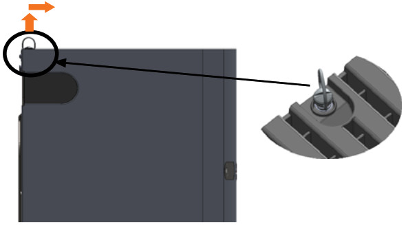 E) While pulling out the cover, make sure that the indicated snaps at the bottom of the unit are being unlocked.F) Simillarly for dismounting the Encharge 10 Cover, please follow the instructions from A to E.
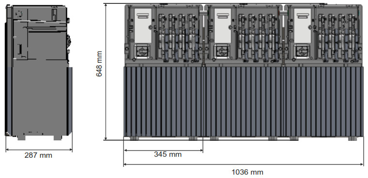 D ) Turn on the AC circuit feeding the Encharge Battery(ies).E ) The Encharge battery LED(s) flashes blue for the duration of the startup process and then start flashing green until the startup process is complete. If the LED(s) is not flashing blue and then green, see the following troubleshooting section and Enphase Ensemble Troubleshooting Guide.
CONFIGURE and ACTIVATE
A ) Use the Enphase Installer Toolkit to commission the Encharge Battery(ies). Once connected to the IQ Envoy, refer to the Installer Toolkit help topics for more information.B ) After the IQ Envoy has detected the Encharge Battery(ies), the Encharge LEDs operate as described in the following section.
OPERATION
a LED overviewAfter being commissioned, the LED flashes yellow while each Encharge Battery boots up. If the LED rapidly flashes green for more than two minutes, the battery is in trickle charge mode and will remain so until it reaches a minimum state of charge (up to 30 minutes). After the Encharge Battery is booted up, the LED becomes blue or green depending on the charge level. If the LED flashes yellow after one hour or changes to a flashing red state, contact Enphase Customer Support at enphase.com/en-us/support/contact.
| State | Description |
| Uncommissioned | |
| Flashing blue | After booting up, when Encharge has paired with an IQ Envoy but has not passed the commissioning three-way handshake to confirm that it is an Enphase device. |
| Flashing green | After passing the three-way handshake with the IQ Envoy. |
| After commissioning (normal operation)* | |
| Rapidly flashing yellow | Starting up / Establishing communications |
| Red flashes in sequences of 2 | Error. See “Troubleshooting”. |
| Solid yellow | Not operating due to high temperature. See “Troubleshooting”. |
| Solid blue or green | Idle. Color transitions from blue to green as state of charge increases. You can check Enlighten for charge status. |
| Slowly flashing blue | Discharging |
| Slowly flashing green | Charging |
| Slowly flashing yellow | Sleep mode activated |
| Off | Not operating. See “Troubleshooting”. |
* Encharge batteries have a one-hour orphan timer. If the IQ Envoy stops communicating with them, after one hour the Encharge batteries return to an “uncommissioned” state.
b TroubleshootingIf the Encharge Battery(ies) are not operating correctly, perform the following steps. If the issue persists, contact Enphase Customer Support at enphase.com/en-us/support/contact.A ) If the Encharge Battery(ies) do not operate, check the temperature in the room and increase cooling and/or ventilation as required. Check that the front, top, and sides of the Encharge batteries have at least 15cm (six inches) of unobstructed clearance.B ) If the Encharge LED is off, turn off the breaker for the branch circuit, wait for at least one minute, and turn it back on.NOTE: During a brownout or blackout, the Encharge powers down automatically. This is normal. When power is restored, it automatically starts up again.C ) If you do not see Encharge information in Enlighten, check that the IQ Envoy and the Internet connection are working. If the issue persists, contact Enphase Customer Support at enphase.com/en-us/support/contact.
Limitation of Use:Your Encharge storage unit is not intended for use as a primary or backup power source for life-support systems, other medical equipment, or any other use where product failure could lead to injury, loss of life, or catastrophic property damage. Enphase disclaims any and all liability arising out of any such use of your Encharge storage unit. Further, Enphase reserves the right to refuse to provide support in connection with any such use and disclaims any and all liability arising out of Enphase’s provision of, or refusal to provide, support for your Encharge storage device in such circumstances.
SAFETY
IMPORTANT SAFETY INSTRUCTIONS. SAVE THESE INSTRUCTIONS. This guide contains important instructions that you must follow during installation and maintenance of the Enphase Encharge Battery(ies). Failing to follow any of these instructions may void the warranty (enphase.com/warranty).
In Case of Fire or Other EmergencyIn all cases:
- If safe to do so, switch off the AC breaker for the Encharge Battery circuit, and if an isolator switch is present, switch off the AC isolator for the Encharge Battery circuit.
- Contact the fire department or other required emergency response team.
- Evacuate the area.
In case of fire:
- When safe, use a fire extinguisher. Suitable types are A, B, and C dry chemical fire extinguishers. Additional extinguishing media include carbon dioxide, or alcohol-resistant foams.
In case of flooding:
- Stay out of the water if any part of the Encharge Battery(ies) or wiring is submerged.
- If possible, protect the system by finding and stopping the source of the water, and pumping it away.
- If water has contacted the battery, call your installer to arrange a inspection. If you are sure that water has never contacted the battery, let the area dry completely before use.
In case of unusual noise, smell or smoke:
- Ensure nothing is in contact with the Encharge Battery(ies) or in the venting area of the Encharge Battery(ies).
- Ventilate the room.
- Contact Enphase Customer Support at enphase.com/en-us/support/contact.
Safety and Advisory Symbols
| DANGER: This indicates a hazardous situation, which if not avoided, will result in death or serious injury. | |
| WARNING: This indicates a situation where failure to follow instructions may be a safety hazard or cause equipment malfunction. Use extreme caution and follow instructions carefully. | |
| NOTE: This indicates information particularly important for optimal system operation. Follow instructions carefully. |
Safety Instructions
| DANGER: Risk of electric shock. Risk of fire. Only qualified electricians should install, troubleshoot, or replace the Encharge Battery(ies). | |
| DANGER: Risk of fire or explosion. Only qualified personnel, using personal protective equipment (PPE) should transport or handle the Encharge Battery(ies). | |
| DANGER: Risk of explosion. Do not dispose of Encharge Battery(ies) in a fire or by burning. The Encharge Battery(ies) can explode. | |
| DANGER: Risk of fire or explosion. This product is designed for stationary installation only and should be used accordingly. It is not designed for mobile applications such as installation and on vehicles and trailers and should not be used in such applications. | |
| DANGER: Risk of fire. During use, when stored, or during transport, keep the Encharge Battery(ies) in an area that is well ventilated and protected from the elements, where the ambient temperature and humidity are within -15° C to 55° C (5° F to 131° F) and 5% to 100% RH, non-condensing, preferably out of direct sunlight. Do not install the Encharge Battery(ies) at elevations over 2500 m (8,200 feet) above sea level. | |
| DANGER: Risk of fire. If the Encharge Battery(ies) generate smoke, remove AC power from the Enphase System and turn the DC connect switch to the off position so that charging/discharging stops. | |
| DANGER: Risk of electric shock. Risk of fire. Do not attempt to repair the Encharge Battery(ies). DO NOT OPEN THE ENCLOSURE — NO SERVICEABLE PARTS. Tampering with or opening the Encharge Battery(ies) will void the warranty. If the Encharge Battery(ies) fail, contact Enphase Customer Support for assistance at enphase.com/en-us/support/contact. | |
| DANGER: Risk of electric shock. Do not use Enphase equipment in a manner not specified by the manufacturer. Doing so may cause death or injury to persons, or damage to equipment. | |
| DANGER: Risk of electric shock. Do not install the Encharge Battery(ies) without first removing AC power from the photovoltaic system. Disconnect the power coming from the photovoltaics before servicing or installing. | |
| DANGER: Risk of electric shock. Always de-energize the AC branch circuit during an emergency and/or before servicing the Encharge Battery(ies). Never disconnect the DC switch under load. | |
| DANGER: Risk of electric shock. Risk of high short-circuit current. Observe the following precautions when working on batteries:• Remove watches, rings, or other metal objects.• Use tools with insulated handles.• Wear insulating gloves and boots.• Do not lay tools or metal parts on top of batteries. | |
| DANGER: Risk of electric shock. Risk of fire. Do not work alone. Someone should be in the range of your voice or close enough to come to your aid when you work with or near electrical equipment. | |
| DANGER: Risk of fire. Do not allow or place flammable, sparking, or explosive items near the Encharge Battery(ies). | |
| DANGER: Risk of electric shock. In areas where flooding is possible, install the Encharge Battery(ies) at a height that prevents water ingress. | |
| DANGER: Risk of electric shock. AC voltage is present at the output when the DC switch is on. | |
| DANGER: Risk of electric shock. Branch circuit protection must be off before switching DC power on or off. | |
| DANGER: Risk of electric shock. The DC switch must locked in the OFF position for shipping and service. | |
| WARNING: Risks of electric shock, energy hazard, and chemical hazard. Do not disassemble. | |
| WARNING: Risk of equipment damage. During use, storage, transport, or installation, always keep the Encharge Battery(ies) in an upright position. | |
| WARNING: You must install the Encharge Battery(ies) only on a suitable wall using an Enphase wall-mount bracket. | |
| WARNING: Before installing or using the Encharge Battery(ies), read all instructions and cautionary markings in this guide and on the equipment. | |
| WARNING: Do not install or use the Encharge Battery(ies) if it has been damaged in any way. | |
| WARNING: Do not exceed the maximum number (3) of Encharge Batteries in a 20 A AC branch circuit. | |
| WARNING: Do not sit on, step on, place objects on, or insert objects into the Encharge Battery(ies). | |
| WARNING: Do not place beverages or liquid containers on top of the Encharge Battery(ies). Do not expose the Encharge Battery(ies) to liquids or flooding. | |
| WARNING: When placing the Encharge Battery(ies) in storage, ensure that AC power is not present and that the DC switch is in the Locked position. While in storage, damage to the battery can occur from over-discharge. If the battery state of charge falls to 0%, the Encharge Battery(ies) can be damaged or destroyed. Because of this, the Encharge Battery(ies) must only be stored for a limited amount of time.• The Encharge Battery(ies) must be installed and energized by the “Must Energize By” date on the shipping box label.• The Encharge Battery(ies) must have a charge state of no more than 30% when placed in storage. To do this, the Encharge Battery(ies) must be placed in Sleep Mode.• If the Encharge Battery(ies) is already been installed, it must be placed into Sleep Mode prior to uninstalling. A battery in Sleep Mode can be stored a maximum of two months after being placed into Sleep Mode. | |
| NOTE: Perform installation and wiring, including protection against lightning and resulting voltage surge, in accordance with all applicable local electrical codes and standards. | |
| NOTE: Because Encharge Battery(ies) are grid forming, you must install signage in ccordance with NEC articles 705, 706, and 710. | |
| NOTE: Using unapproved attachments or accessories could result in damage or injury. | |
| NOTE: Install properly rated over current protection as part of the system installation. | |
| NOTE: To ensure optimal reliability and to meet warranty requirements, the Encharge Battery(ies) must be installed and/or stored according to the instructions in this guide. | |
| NOTE: The Encharge Battery(ies) are compatible only with the IQ Envoy communications gateway properly fitted with USB hub, USB radios, and production and consumption CTs. The IQ Envoy is required for operation of the Encharge Battery(ies). Earlier versions of the Enphase Envoy communications gateway are incompatible. | |
| NOTE: The Enphase Encharge Battery(ies) are intended to operate with an Internet connection. Failure to maintain an Internet connection may have an impact on the warranty. See Limited Warranty for full terms and services (enphase.com/warranty). | |
| NOTE: When replacing Enphase Encharge Battery(ies), you must replace with an Encharge Battery(ies) of the same type, with the same AC current rating. | |
| NOTE: When disconnected and stored, no automatic charge of the battery is possible. | |
| NOTE: Properly mount the Encharge Battery(ies). Ensure that the mounting location is structurally suited to bearing the weight of the Encharge Battery(ies). | |
| NOTE: During use, storage, and transport, keep the Encharge Battery(ies):• Properly ventilated• Away from water, other liquids, heat, sparks, and direct sunlight• Away from excessive dust, corrosive and explosive gases, and oil smoke• Away from direct exposure to gas exhaust, such as from motor vehicles• Free of vibrations• Away from falling or moving objects, including motor vehicles. If mounted in the path of a motor vehicle, we recommend a 91 cm (36-inch) minimum mounting height• At an elevation of lower than 2,500m (8,200 feet) above sea-level• In a location compliant with fire safety regulations• In a location compliant with local building codes and standards | |
| NOTE: Conditions for the Encharge installation site apply also to storage conditions. |
Enphase Customer Support: enphase.com/en-us/support/contact
 Environmental Protection
ELECTRONIC DEVICE: DO NOT THROW AWAY. Waste electrical products should not be disposed of with household waste. Proper disposal of batteries is required. Refer to your local codes for disposal requirements.
References
[xyz-ips snippet=”download-snippet”]