![]() QUICK INSTALL GUIDEModel number: EP200G101-M240US00Install the EnphaseEnpower Smart Switch
QUICK INSTALL GUIDEModel number: EP200G101-M240US00Install the EnphaseEnpower Smart Switch
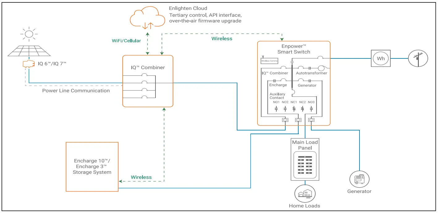
To install the Enphase Enpower™ smart switch and the Enphase Empower wall-mount bracket, read and follow all warnings and instructions in this guide and in the Enphase Empower Installation and Operation Manual at enphase.com/support. Safety warnings are listed on the back of this guide. These instructions are not meant to be a complete explanation of how to design and install an energy storage system. All installations must comply with national and local electrical codes and standards. Only qualified electricians shall install, troubleshoot, or replace the Enpower.The Enphase Ensemble System includes the Enphase Enpower™ smart switch with Microgrid Interconnection Device (MID) capability, which consolidates interconnection equipment into a single enclosure and streamlines grid-independent capabilities of PV and storage installations by providing a consistent, pre-wired solution for residential applications. Along with MID functions, it includes PV, storage, and generator input circuits.For installing Enpower with 3rd party PV inverter please refer to the planning guide document on Enphase Energy Storage System for third party PV inverters online on Enphase website.NOTE: The same installation scenarios also apply to systems with legacy M-series microinverters and Envoy-S Metered as the communications gateway.Scenario 1:Whole home backup with Enpower as service entrance and PV combiner connected to Enpower. This is the preferred configuration for back up of the entire mainload panel. This configuration supports up to an 60A breaker for the PV circuit and an 60A breaker for battery storage.
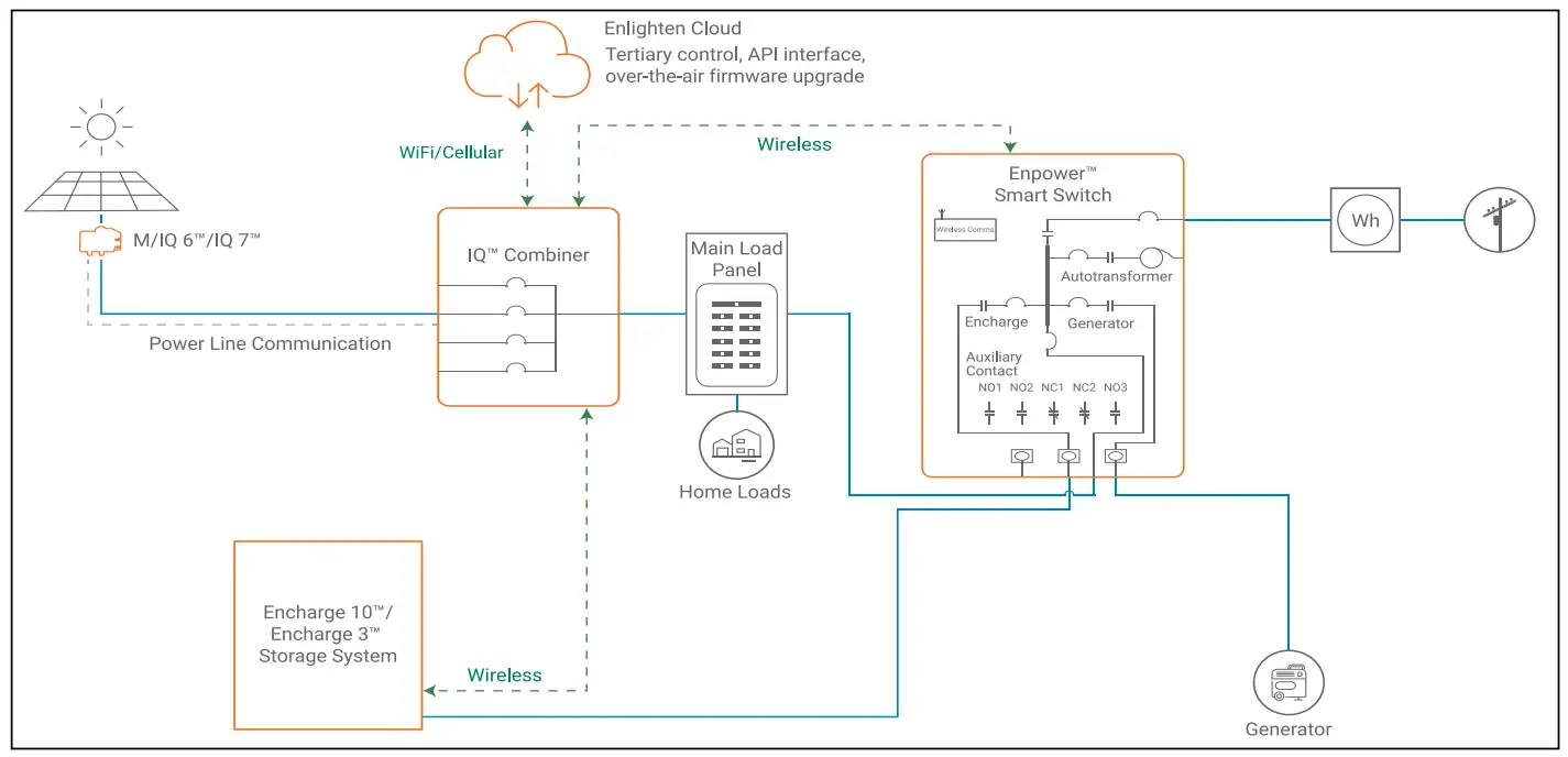
Scenario 2:Whole-home backup with Enpower as service entrance and PV combiner connected to main load panel. This is the preferred configuration when you back up the entire main load panel, and the size of the PV combiner circuit is more than 60A. In this configuration, the PV combiner circuit connection space in Enpower is left vacant. When existing PV combiner circuits are connected to the main load panel, and you want to add battery storage to the system, you can keep the PV combiner connected to the main load panel and connect only the battery storage system to Enpower.
Scenario 3:Partial home backup with main load panel as service entrance and PV combiner connected to Enpower. When PV circuits breaker size is less than 60A, this is the preferred configuration for partial home backup with subpanel.
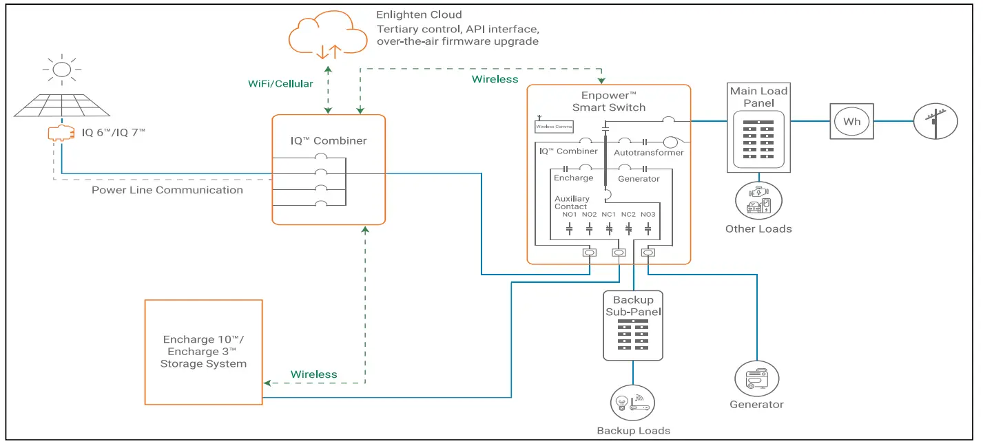
Scenario 4:Partial home backup with main load panel as service entrance and PV combiner connected to subpanel. This is the preferred connection configuration for partial some ackup using a subpanel when the PV circuit breaker size is more than 60A. The space available in Enpower for combiner (solar) connection is left vacant.

PREPARATION
A ) Inspect the packaging and the Enpower for damage. Do not install or use the Enpower if it has been damaged in any way.B ) Ensure that you have the following:
- One Enphase Enpower smart switch. The Enpower shipping box contains an Enphase Enpower, mounting bracket, mounting hardware, and literature kit (bag with labels and accessories: 150-00148). Among the accessories are four-pin receptacles/dry contacts that will be used for controlling external power relays.
![]() WARNING: The Enpower smart switch weighs 38.5 kg (85 lbs) and will require two persons to lift the unit.C ) Make sure you have the following required items:
WARNING: The Enpower smart switch weighs 38.5 kg (85 lbs) and will require two persons to lift the unit.C ) Make sure you have the following required items:
- Enphase Encharge™ storage system, which is required for off-grid applications.
- The Enphase Enpower requires a wireless connection to an Envoy, which requires an Internet connection. Failure to maintain an Internet connection may have an impact on the warranty. See enphase.com/warranty for full terms and services.
- Wireless USB Adapter (COMMS-KIT-01) to be installed at Envoy for communications with Encharge and Enpower. Includes USB cablefor connection to Envoy and allows wireless communication with Encharge and Enpower.
- Two current transformers (CT-200-SPLIT) for consumption monitoring
- One current transformer (CT-200-SOLID) for production metering
- Enpower lifting handles (EP200G-HNDL-R1).
- Eaton BR Series breakers, rated maximum 60A for Encharge storage system and Enphase IQ™ combiner.
- If breakers are required at the input or output to Enpower, use Eaton, Type CSR breakers rated 100 A, 125 A, 150 A, 175 A or 200 A.
- Tools: conduit (with fittings and fitting tools), drill, 5/32 inch pilot bit (or metric equivalent), screwdriver, socket, wrench, adjustable wrench, torque wrench, level, 5/32 inch Allen key (or metric equivalent), conductor stripper,electrician’s hole saw (2 inches) kit or punch set, and stud finder if installing on studs.
- Conduit fittings (hubs) are required for all installations, and NEMA Type 3 conduit fittings (hubs) are needed when installing out of doors (one for each used conduit opening).
- Conduit ground hub rings.NOTE: Conduit entry is allowed only through the bottom or bottom sides of the unit.
- Three #10, 1/4”, or 5/16” lag bolts or screws, 7.6cm (three inches) long (depending on attachment wall), for each wall-mount bracket. Check with a structural engineer and local standards for local requirements.
- ashers for use between fastener heads and wall-mount bracket.
- Conductors rated at 75°C. For sizes, refer to the table on the unit and to local codes.
- Overcurrent protection: maximum in accordance with local standards.
- The door sheet metal is not required to be grounded, since it is protected from live parts by other grounded metal and insulating plastic materials, thus is considered unlikely to become energized.
INSTALLATION
Use the Enphase Installer Toolkit™ mobile app for iOS and Android devices.It allows installers to configure the system while on-site, eliminating the need for a laptop and improving installation efficiency.NOTE: Only one Enpower can be commissioned in one system. Multiple Enpowers can exist on the same site but they need to be in separate systems, i.e. separate Enlighten/ITK activations.
1 Plan a location for the EnpowerThe Enpower housing is NEMA type 3R and you can install it indoors or outdoors.![]() WARNING: Protection against lightning and resulting voltage surge must be in accordance with local standards.A ) Follow all local codes and standards when planning for and installingthe Enphase Enpower Smart Switch.B ) Choose a well-ventilated location where the ambient temperature is within -40° C to 50° C (-40° F to 122° F), preferably out of direct sunlight.C ) Ensure that the mounting location can sustain the weight of the Enpower and mounting bracket 38.5 kg (85 lbs). The wall must include studs that can bear 38.5 kg (85 lbs) or can be of masonry or other suitable structure that can bear the weight.D ) Check the mounting location clearances:•Indoors: at least 15cm (six inches) off the ground, 15cm (six inches) from the ceiling, and 15cm (six inches) on Enpower dimensions on each side.• Outdoors: at least 91cm (three feet) off the ground and 15cm (six inches) on each side.
WARNING: Protection against lightning and resulting voltage surge must be in accordance with local standards.A ) Follow all local codes and standards when planning for and installingthe Enphase Enpower Smart Switch.B ) Choose a well-ventilated location where the ambient temperature is within -40° C to 50° C (-40° F to 122° F), preferably out of direct sunlight.C ) Ensure that the mounting location can sustain the weight of the Enpower and mounting bracket 38.5 kg (85 lbs). The wall must include studs that can bear 38.5 kg (85 lbs) or can be of masonry or other suitable structure that can bear the weight.D ) Check the mounting location clearances:•Indoors: at least 15cm (six inches) off the ground, 15cm (six inches) from the ceiling, and 15cm (six inches) on Enpower dimensions on each side.• Outdoors: at least 91cm (three feet) off the ground and 15cm (six inches) on each side.
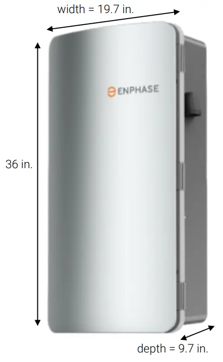
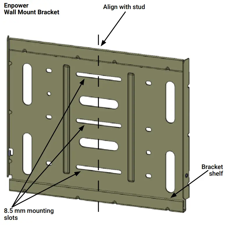
E ) Ensure that there are no pipes or electrical conductors where you plan to drill.F ) Plan to maintain at least 90cm (three feet) of clearance in front of the Enpower.G ) Consider the dimensions of the Enpower, easy access, unit height, conduit entry, and length of cable when selecting the location.H ) Select a location where you can interconnect to the site’s load center using the Enphase Enpower.2. Install the wall-mount bracketA ) Mark a plumb line over the wall stud as a guide.![]() WARNING! Multiple risks. Make sure not to drill or attach into electric wiring or pipes that are in the wall!B ) Remove the wall mount bracket only from the shipping box.C ) Place the wall-mount bracket on the wall so that the mounting holes in the middle of the bracket align with the center of the stud. Use a level to keep the bottom of the wall-mount bracket level.D ) Use the #10, 1/4”, or 5/16” wood screws (or masonry attachments if installing in masonry) to attach the bracket using one screw and washer for each slot. The slot size of the Enpower wall mount bracket is 8.5mm. Use an appropriately sized washer for each of the screws, and check with a structural engineer and local standards for local requirements.E ) Verify that the wall-mount bracket is level, solidly attached to the wall, and oriented for upright installation of the Enpower.
WARNING! Multiple risks. Make sure not to drill or attach into electric wiring or pipes that are in the wall!B ) Remove the wall mount bracket only from the shipping box.C ) Place the wall-mount bracket on the wall so that the mounting holes in the middle of the bracket align with the center of the stud. Use a level to keep the bottom of the wall-mount bracket level.D ) Use the #10, 1/4”, or 5/16” wood screws (or masonry attachments if installing in masonry) to attach the bracket using one screw and washer for each slot. The slot size of the Enpower wall mount bracket is 8.5mm. Use an appropriately sized washer for each of the screws, and check with a structural engineer and local standards for local requirements.E ) Verify that the wall-mount bracket is level, solidly attached to the wall, and oriented for upright installation of the Enpower.![]() WARNING! Risk of injury and equipment damage. Do not mount an Enpower on a bracket that is not properly attached to a wall.
WARNING! Risk of injury and equipment damage. Do not mount an Enpower on a bracket that is not properly attached to a wall.![]() WARNING! Risk of injury and equipment damage. Protect the Enpower from impact damage and improper use.
WARNING! Risk of injury and equipment damage. Protect the Enpower from impact damage and improper use.
3 Unbox and mount the Enpower on the wall![]() WARNING: Risk of injury. Take care when lifting. The Enpower is heavy 38.5 kg (85 lbs).
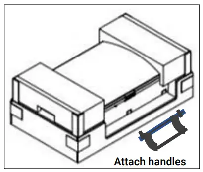
WARNING: Risk of injury. Take care when lifting. The Enpower is heavy 38.5 kg (85 lbs).![]() WARNING! Risk of injury and equipment damage. Avoid dropping the Enpower. Doing so may create a hazard, cause serious injury, and/ or damage the equipment.A ) Remove the upper Enpower box, and locate the slots on both sides of the Enpower enclosure.B ) Locate the lifting handles (sold separately) and check that the plungers are extended and ready to engage into the Enpower slots.C ) Align one handle on one side of the Enpower and press the handle into the slots, and slide the handle toward the top of the Enpower enclosure until it clicks into place. Check that the handle is secure.D ) Repeat on the other side with the second handle.
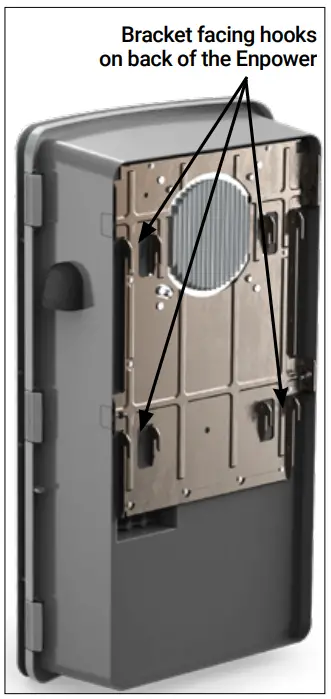
WARNING! Risk of injury and equipment damage. Avoid dropping the Enpower. Doing so may create a hazard, cause serious injury, and/ or damage the equipment.A ) Remove the upper Enpower box, and locate the slots on both sides of the Enpower enclosure.B ) Locate the lifting handles (sold separately) and check that the plungers are extended and ready to engage into the Enpower slots.C ) Align one handle on one side of the Enpower and press the handle into the slots, and slide the handle toward the top of the Enpower enclosure until it clicks into place. Check that the handle is secure.D ) Repeat on the other side with the second handle.![]() WARNING! Risk of injury and equipment damage. Two persons are required to lift the Enpower.E ) Use the lifting handles, take the Enpower from the packaging, making sure it is top side up (upright). Enpower is designed only for vertical installation without inclination (must be level).F ) Lift the Enpower slightly above the installed wall mount bracket and allow it to slide down so that the bracket facing hooks are set into both the top and bottom shelves of the all mounting bracket.G ) Allow the Enpower to slide down until the Enpower is fully seated on the wall-mount bracket shelf.
WARNING! Risk of injury and equipment damage. Two persons are required to lift the Enpower.E ) Use the lifting handles, take the Enpower from the packaging, making sure it is top side up (upright). Enpower is designed only for vertical installation without inclination (must be level).F ) Lift the Enpower slightly above the installed wall mount bracket and allow it to slide down so that the bracket facing hooks are set into both the top and bottom shelves of the all mounting bracket.G ) Allow the Enpower to slide down until the Enpower is fully seated on the wall-mount bracket shelf.
![]() WARNING! Risk of injury and equipment damage. Do not release the Enpower until you ensure that the Enpower is fully seated in the wall-mount bracket shelf.H ) For each handle, pull the plunger tabs to release them and remove the lift handles.I ) Reserve the handles for the next installation.J ) On the bottom handle mounts, use the two provided partial-threaded custom M6 screws to secure each side of the Enpower and tighten to 0.5 N•m (4.4 lb•in) or less.The threaded portion of the screw engages with the bracket, while the unthreaded portion of the screw engages with the hole in the bracket to prevent vertical movement of thebracket.
WARNING! Risk of injury and equipment damage. Do not release the Enpower until you ensure that the Enpower is fully seated in the wall-mount bracket shelf.H ) For each handle, pull the plunger tabs to release them and remove the lift handles.I ) Reserve the handles for the next installation.J ) On the bottom handle mounts, use the two provided partial-threaded custom M6 screws to secure each side of the Enpower and tighten to 0.5 N•m (4.4 lb•in) or less.The threaded portion of the screw engages with the bracket, while the unthreaded portion of the screw engages with the hole in the bracket to prevent vertical movement of thebracket.
![]() WARNING! Risk of injury and equipment damage. Do not skip this step. Without these screws in place, the Enpower may fall and cause injury or damage if bumped or shaken.K ) Use the four filler plates, provided in the lit kit, to cover the screws.4 Install breakers as neededThe Enpower includes one two-pole 40A circuit breaker that feeds the neutral forming transformer (NFT). You can install additional breakers if needed. You must follow all NEC and local electrical codes. Install breakers as needed for the AC grid, main load, Enphase IQ Combiner, Enphase Encharge batteries, and generator.These breakers are not included and must be ordered separately.NOTE: You must install a backup loads breaker if required by local code.
WARNING! Risk of injury and equipment damage. Do not skip this step. Without these screws in place, the Enpower may fall and cause injury or damage if bumped or shaken.K ) Use the four filler plates, provided in the lit kit, to cover the screws.4 Install breakers as neededThe Enpower includes one two-pole 40A circuit breaker that feeds the neutral forming transformer (NFT). You can install additional breakers if needed. You must follow all NEC and local electrical codes. Install breakers as needed for the AC grid, main load, Enphase IQ Combiner, Enphase Encharge batteries, and generator.These breakers are not included and must be ordered separately.NOTE: You must install a backup loads breaker if required by local code.![]() WARNING! Risk of injury and equipment damage. Use only the breakers listed in this table.List of allowed breakers and hold down kits:
WARNING! Risk of injury and equipment damage. Use only the breakers listed in this table.List of allowed breakers and hold down kits:
| Enphase Model No. | Type and Eaton part no. |
| BRK-100A-2P-240V | • Main Breaker, 2 pole, 100A, 25kAIC, CSR2100 |
| BRK-125A-2P-240V | • Main Breaker, 2 pole, 125A, 25kAIC, CSR2125N |
| BRK-150A-2P-240V | • Main Breaker, 2 pole, 150A, 25kAIC, CSR2150N |
| BRK-175A-2P-240V | • Main Breaker, 2 pole, 175A, 25kAIC, CSR2175N |
| BRK-200A-2P-240V | • Main Breaker, 2 pole, 200A, 25kAIC, CSR2200N |
| BRK-20A-2P-240V-B | • Circuit Breaker, 2 pole, 20A, 10kAIC, BR220B |
| BRK-30A-2P-240V | • Circuit Breaker, 2 pole, 30A, 10kAIC, BR230B |
| BRK-40A-2P-240V | • Circuit Breaker, 2 pole, 40A, 10kAIC, BR240B |
| BRK-60A-2P-240V | • Circuit Breaker, 2 pole, 60A, 10kAIC, BR260 |
| EP200G-NA-HD200A | • Eaton type BR circuit breaker hold-down screw kit, BRHDK125 |
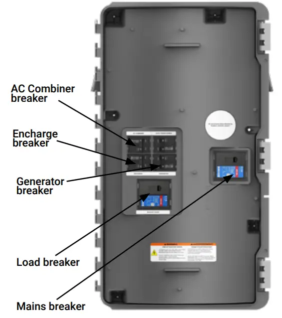
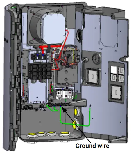
Breaker installation positions are noted in the diagram.A ) Ensure that the Enpower is completely de-energized.B ) Open the three latches that lock the enclosure door. To release the latch, pull the latch handle forward and then to the right. With all the latches opened, swing opens the enclosure door.![]() WARNING: Risk of equipment damage. Do not remove the pre-installed solar shield attached to the enclosure door.C ) Use a Phillips screwdriver to loosen the six screws along the periphery of the dead front. Support the dead front to keep it from falling while performing the next step.D ) While supporting the dead front, use a screwdriver to disconnect the dead front ground wire from the grounding bar before the dead front is removed.E ) Use the two tabs on the front to assist in handling the dead front during the removal. Keep the dead front and screws handy as you will need them later.
WARNING: Risk of equipment damage. Do not remove the pre-installed solar shield attached to the enclosure door.C ) Use a Phillips screwdriver to loosen the six screws along the periphery of the dead front. Support the dead front to keep it from falling while performing the next step.D ) While supporting the dead front, use a screwdriver to disconnect the dead front ground wire from the grounding bar before the dead front is removed.E ) Use the two tabs on the front to assist in handling the dead front during the removal. Keep the dead front and screws handy as you will need them later.![]() WARNING: Risk of electric shock. To maintain the warranty, do not modify the dead front other than to remove or replace filler plates, as needed.F ) If you install the main breaker or load breaker, remove the standard lugs before installing the Eaton CSR breaker. By default, lugs are provided in the Enpower unit for connection to the mains and to the load. In case of usage without breakers, the conductors are connected directly to these lugs. When breakers are used, the lugs are replaced with breakers during installation.G ) Remove a filler plate from the dead front for each breaker position you will use. Refer to the breaker position diagram to the left. To remove the filler plate, press the two snaps inward while gently pushing the filler plate out.H ) For the Encharge, AC Combiner, or Generator connection, snap the appropriately sized BR series two-pole Eaton breaker onto the busbar, using only the breaker positions indicated in the diagram on the door of the unit. Breaker functional positions are not interchangeable with one another. The wires to be connected to each breaker are located beside each breaker position. Remove the heat shrink cap on the wire ends before inserting it into the breaker.
WARNING: Risk of electric shock. To maintain the warranty, do not modify the dead front other than to remove or replace filler plates, as needed.F ) If you install the main breaker or load breaker, remove the standard lugs before installing the Eaton CSR breaker. By default, lugs are provided in the Enpower unit for connection to the mains and to the load. In case of usage without breakers, the conductors are connected directly to these lugs. When breakers are used, the lugs are replaced with breakers during installation.G ) Remove a filler plate from the dead front for each breaker position you will use. Refer to the breaker position diagram to the left. To remove the filler plate, press the two snaps inward while gently pushing the filler plate out.H ) For the Encharge, AC Combiner, or Generator connection, snap the appropriately sized BR series two-pole Eaton breaker onto the busbar, using only the breaker positions indicated in the diagram on the door of the unit. Breaker functional positions are not interchangeable with one another. The wires to be connected to each breaker are located beside each breaker position. Remove the heat shrink cap on the wire ends before inserting it into the breaker.
Required practices when torquing connections:• Always follow NEC 2017 110.4 (D) dictates.• You must use a calibrated torque tool to achieve the indicated torque values.• Use tamper-proof torque mark/ paint after torquing connections.
|
Connections |
Wire size (AWG) |
Torque (N•in / Il•in) |
| Main lugsBackup load lugs (use a 1/4″ hex drive) | Cu/AL: 300 KCMIL -1 | 31.1 /275 |
| CSR breakers bottom wiring lugs | Cu/AL: 300 KCMIL – 2 | 28.2 /250 |
| BR breakers (wire provided) | 6 | 3.1 /27 |
| AC Combiner lugs, Encharge lugs, and Generator lugs | 14 – 1084 – 62 – 3 | 2.8 / 253.4 / 303.9 / 354.5 / 40 |
| Neutral – large lugs (use a 3/8″ hex drive) | Cu/AL: 300 KCMIL – 6 | 31.1 / 275 |
| Neutral and ground bars | ||
| Large holes (5/16-24 UNF) | 1/0 – 34 – 6810 -14 | 5.6 / 505.1 / 454.5 / 404.0 / 35 |
| Small holes (10-32 UNF) | 6 – 810 -14 | 2.8 / 251.7 / 15 |
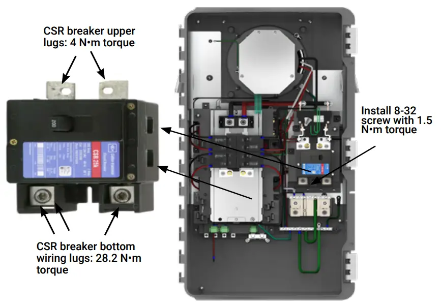
I ) Install each breaker by rocking it to the left, catching the clips that hold it in place. Then rock the breaker to the right so it is fully seated and secure.J) The generator breaker position can be used for the below purposes if the generator is unused:1. Power the control transformer to enable the auxiliary contact load/ PV shedding feature2. Connect the subpanel backup load breaker for <100A load subpanel.You can connect the main breaker of the subpanel to this position, since the load side lugs in Empower do not support <100A breaker or <1AWG wires.Ensure you stick the “BACKUP LOADS” label from the load control kit, on top of the “GENERATOR” embossing, on the Enpower dead front.K ) For the main load breaker, use an appropriately sized CSR Eaton breaker. Install at the location indicated in the diagram on the door of the unit.L ) Remove the mains/load lugs by unscrewing the two nuts holding the lugs. Re-use the same nuts to fix the CSR breakers in the same position. Torque to 4 N•m (35.4 lb•in).M ) Use the 8-32 screw (from the lit kit marked 150-00148 that ships with the Enpower) to secure the mains breaker (not the load breaker). Use a T20 drive to tighten the 8-32 screw to 1.5 N•m (13.3 lb•in). Do not use any other screw.
N ) Check that all breakers are properly seated.O ) Use the included stowed conductors, as labeled, to wire the circuit breaker(s) for the Encharge batteries, Enphase Combiner, and generator, as needed. The stowed conductors are provided with crimped-on ferrules with end caps to prevent accidental contact. Remove the conductor end caps as needed.P ) Torque the breaker connections as listed in the following and in the conductor table on the unit.Q ) Purchase and install an Eaton type BR circuit breaker hold-down screw kit (SKU: EP200G-NA-HD-200A) to secure only the Encharge and generator double-pole circuit breaker(s).
5 Wire the field connections![]() DANGER! Risk of electric shock. Check that all circuits connecting to the Enpower are de-energized before wiring.
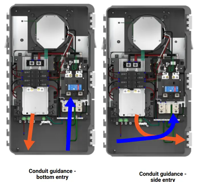
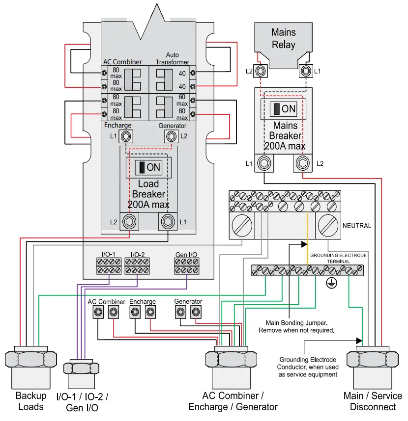
DANGER! Risk of electric shock. Check that all circuits connecting to the Enpower are de-energized before wiring.![]() WARNING! Do not install consumption CTs on the conductors above the common busbar or on the main conductors below the main breaker if the main breaker is used as a service entrance. If the main breaker is the service entrance breaker, you must install the CTs on the conductors directly above the MID relay.A ) Drill conduit entry holes as needed, and install conduit grounding lugs for each opening. Be sure to reseal unused conduit entry holes with sealing plugs.NOTE: Main supply conductors may enter the Enpower from the bottom or from the bottom-left side. Backup load conductors may enter the Enpower from the bottom or bottom-right side. Encharge, Combiner and generator conductors may enter from the bottom, bottom-left or bottom-right sides.B ) Size the conductors (Line, Neutral and Ground) depending on the breaker or fuse, proper ampacity, and voltage rise requirements according to local codes.Refer to the conductor rating table on the door of the Enpower.C ) If the Enpower is not installed as service equipment, you must remove the main bonding jumper connected between the grounding bar and the neutral assembly.Refer to the wiring diagram.NOTE: Do not modify or rewire any of the other pre-installed wiring or bonding connections in the Enpower.D ) If Enpower is installed as service equipment• Connect a grounding electrode conductor to the grounding bar.• From the lit kit, place the label “GROUNDING ELECTRODE TERMINAL” adjacent to the grounding bar.• From the lit kit, place the label “SUITABLE FOR USE AS SERVICE EQUIPMENT” / “MAIN SERVICE DISCONNECT” on the deadfront near the main breaker/service disconnect.• If Enpower is not used as service equipment, these labels should not be used.E ) Connect Lines, Neutral, and Ground. For details, refer to the conductor table on the unit for sizes and refer to local codes.
WARNING! Do not install consumption CTs on the conductors above the common busbar or on the main conductors below the main breaker if the main breaker is used as a service entrance. If the main breaker is the service entrance breaker, you must install the CTs on the conductors directly above the MID relay.A ) Drill conduit entry holes as needed, and install conduit grounding lugs for each opening. Be sure to reseal unused conduit entry holes with sealing plugs.NOTE: Main supply conductors may enter the Enpower from the bottom or from the bottom-left side. Backup load conductors may enter the Enpower from the bottom or bottom-right side. Encharge, Combiner and generator conductors may enter from the bottom, bottom-left or bottom-right sides.B ) Size the conductors (Line, Neutral and Ground) depending on the breaker or fuse, proper ampacity, and voltage rise requirements according to local codes.Refer to the conductor rating table on the door of the Enpower.C ) If the Enpower is not installed as service equipment, you must remove the main bonding jumper connected between the grounding bar and the neutral assembly.Refer to the wiring diagram.NOTE: Do not modify or rewire any of the other pre-installed wiring or bonding connections in the Enpower.D ) If Enpower is installed as service equipment• Connect a grounding electrode conductor to the grounding bar.• From the lit kit, place the label “GROUNDING ELECTRODE TERMINAL” adjacent to the grounding bar.• From the lit kit, place the label “SUITABLE FOR USE AS SERVICE EQUIPMENT” / “MAIN SERVICE DISCONNECT” on the deadfront near the main breaker/service disconnect.• If Enpower is not used as service equipment, these labels should not be used.E ) Connect Lines, Neutral, and Ground. For details, refer to the conductor table on the unit for sizes and refer to local codes.![]() WARNING! Risk of equipment damage. Always connect to two Lines (active), one neutral, and one ground.F ) Connect the AC wires of Enphase Combiner, Encharge batteries, and generator into the terminal lugs at the bottom of the Enpower load center on the left.
WARNING! Risk of equipment damage. Always connect to two Lines (active), one neutral, and one ground.F ) Connect the AC wires of Enphase Combiner, Encharge batteries, and generator into the terminal lugs at the bottom of the Enpower load center on the left.![]() WARNING: Do not connect the AC wires directly into the breakers. The AC wires go into the terminal lugs as shown on the label.G ) After all conductors are connected and secured, check that there are no exposed conductors or stray wires.H ) Gently arrange all the conductors and connectors inside the cabinet.
WARNING: Do not connect the AC wires directly into the breakers. The AC wires go into the terminal lugs as shown on the label.G ) After all conductors are connected and secured, check that there are no exposed conductors or stray wires.H ) Gently arrange all the conductors and connectors inside the cabinet.![]() DANGER! Risk of electric shock. The system is not ready to be energized! Do not close any circuit breaker yet.NOTE: The polarity of L1 and L2 is swapped inside the Eaton CSR series main breakers. Installers should follow L1 and L2 on the following image when installing consumption CTs.
DANGER! Risk of electric shock. The system is not ready to be energized! Do not close any circuit breaker yet.NOTE: The polarity of L1 and L2 is swapped inside the Eaton CSR series main breakers. Installers should follow L1 and L2 on the following image when installing consumption CTs.
*The extra lug near the top right side of NFT (autotransformer) is a manufacturing test terminal intentionally unpopulated with no end-user application.
6. Set Up the Power Control SystemThe Enpower device, when used with Envoy and Production as well as Consumption/PCS CTs enables the Power Control System (PCS) functionality in the Enphase Storage System.
|
Device |
Supported SKU’s |
|
ENV-IQ-AM1-240, ENV-S-AM1-120CT-200-SPLIT(needs 2 units)CT-200-SOLID(included with the envoy)EP200G101-M240US00
|
The Enphase Storage System supports 2 PCS use cases:
- Import Only mode for Energy Storage System (ESS): Enphase Storage System can import power from the Area Electric Power System (EPS) for charging purposes but does not export active power from the ESS to the Area EPS. The ESS mode of Import Only applies irrespective of the configured battery smart profile, i.e., Self-Consumption, Full Backup, or Savings (Time of Use) with optimization. The ESS Import Only mode applies irrespective of whether the solar micro inverters are IQ6/IQ7 or M215/M250.
- Main Panel Upgrade (MPU) avoidance: In the partial home backup scenario, the PCS limits the currents backed into the main panel as allowed by 2020 NEC article 705.13. This ensures that the main panel complies with the NEC article 705.12.
NOTE: This use case is only supported with IQ Envoy and IQ6/7 series inverters.This mode is applicable when the system is configured as in Scenario 3 as described on page 1 of this QIG.The National Electric Code(NEC) 2017 NEC 705.12(B)(2)(3)(b) allows back feed of current from solar/storage into the main panel subject to the following limitBackfeed allowed <= ((120% of busbar rating) – Ampacity of the overcurrent protection device protecting the busbar )/ 125%Enphase, through its Installer Toolkit mobile app, also provides grid profiles that comply with PEL limits for various jurisdictions. In a situation where both the PCS limit and a PEL profile are being used, the maximum current backed from the Enpower to the main panel is always the lower of the PEL limit and the PCS limit.NOTE: Import Only Mode for Energy Storage System is fixed in software and cannot be changed in the field.Configuring PCS In the Enphase Storage SystemA ) Check that you have the following items. You must use the listed CTs and Enphase IQ Envoy or the Envoy-S Metered with the Enpower and Encharge for Power Control System functionality.
- Two current transformers (CT-200-SPLIT) for consumption/PCS monitoring
- One current transformer (CT-200-SOLID) for production metering (included with Envoy)
- IQ Envoy (ENV-IQ-AM1-240) or Envoy-S Metered (ENV-S-AM1-120):The IQ Envoy can be standalone or integrated in an IQ Combiner box.
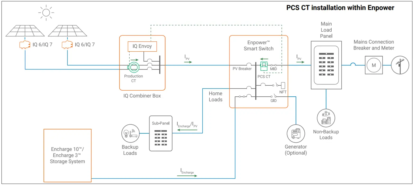
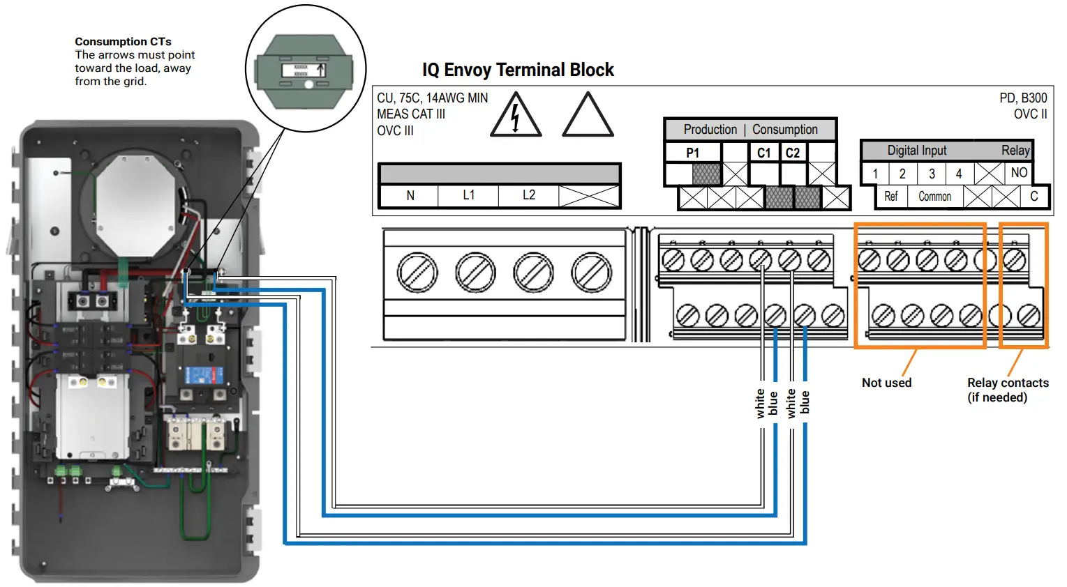
B ) Follow all instructions in the IQ Envoy or IQ Combiner Quick Install Guide to ensure that CTs are installed and wired correctly with the correct polarity. Refer to the following diagram for the locations and polarity (arrow on top of CT) on the CTs.For the whole-home backup configuration, the CTs should be placed in the same location (Production CT in combiner; PCS CT in Enpower) as shown in the diagram PCS CT installation within Enpower.C ) When being used for PCS, you must install the CT-200-SPLIT current transformers inside the Enpower on the conductors above the MID relay.The arrows on the Consumption/PCS CT must point towards the loads, towards the busbar inside the Enpower, or upwards when the CTs are installed above the MID relay. Refer to the image on the next page for the Consumption/PCS CT location and wiring to the IQ Envoy.D ) You must protect all PCS-controlled busbars and/or conductors with suitably rated overcurrent devices that are appropriately sized for the busbar rating or conductor ampacity. A similar setup is required for a system with M215 or M250 microinverters and an Envoy S metered. Refer to the Envoy S metered or IQ Envoy/IQ Combiner QIG to see wiring details for CTs.E) You must indicate, with a label, the maximum current setting for back-feed from Enpower that is controlled by PCS. Apply a label on the Enpower dead front indicating the maximum current setting for back-feed from Enpower that is controlled by PCS. An example of the required label is shown as follows.Record the maximum operating amps value on the label.For more details, refer to the Technical Briefhttps://support.enphase.com/s/article/Technical-Brief-PCS-Integration-in-Enphase-Storage-System
THE MAXIMUM CURRENT BACKED BY THIS SYSTEM TO THE MAIN PANEL MAY BE CONTROLLED ELECTRONICALLY. REFER TO THE MANUFACTURER’S INSTRUCTIONS FOR MORE INFORMATIONPCS CONTROLLED CURRENT SETTING: ___________ AMPS
F ) For Production as well as Consumption/PCS CTs, you must apply the following label to each CT when the system is configured to use PCS-based current limiting.This sensor is part of a Power Control System. Do not remove or disable. Replace with same type and rating.The available space on the CTs for labeling is as follows.Consumption/PCS CT (CT-200-SPLIT):
- Left side: 20mm(vertical) x 14mm(Horizontal)
- Back side: 20mm (vertical) x 20mm(Horizontal)
Production CT (CT-200-SOLID):
- 9mm(vertical) x 30mm(horizontal)
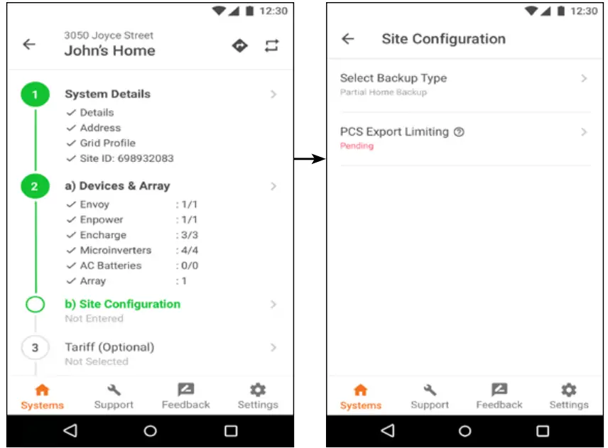
NOTE: The maximum operating currents in controlled busbars or conductors are limited by the settings of the Power Control System (PCS) and may be lower than the sum of the currents of the connected controlled power sources. The settings of the PCS controlled currents may be used for the calculation of the design currents used in the relevantsections of NEC Article 690 and 705.![]() WARNING! Risk of electric shock and fire. Only qualified personnel are permitted to set or change the setting of the maximum operating current of the PCS. The maximum PCS operating current setting shall not exceed the busbar rating or conductor ampacity of any PCS controlled busbar or conductor.G) PCS Export Limiting via ITKPCS ensures the Import Only mode for ESS is always running in the system and the import only mode is not changeable. Energy storage never exports to the grid and therefore never back feeds the main panel in a partial backup scenario if consumption/PCS CTs are placed as outlined in section 6.This section outlines how to configure current export limiting to limit PV current when PV current exceeds the allowed backfeed/export.The MPU avoidance use case of PCS can be enabled via ITK during installation at Step 2 b) Site Configuration as shown in the figure below:NOTE: The MPU avoidance use case requires configuration using the Enphase installer toolkit version v3.0.8 or higher and Envoy softwareversion 6.1.32 or higher.In the site configuration menu, the user can see 2 options:
WARNING! Risk of electric shock and fire. Only qualified personnel are permitted to set or change the setting of the maximum operating current of the PCS. The maximum PCS operating current setting shall not exceed the busbar rating or conductor ampacity of any PCS controlled busbar or conductor.G) PCS Export Limiting via ITKPCS ensures the Import Only mode for ESS is always running in the system and the import only mode is not changeable. Energy storage never exports to the grid and therefore never back feeds the main panel in a partial backup scenario if consumption/PCS CTs are placed as outlined in section 6.This section outlines how to configure current export limiting to limit PV current when PV current exceeds the allowed backfeed/export.The MPU avoidance use case of PCS can be enabled via ITK during installation at Step 2 b) Site Configuration as shown in the figure below:NOTE: The MPU avoidance use case requires configuration using the Enphase installer toolkit version v3.0.8 or higher and Envoy softwareversion 6.1.32 or higher.In the site configuration menu, the user can see 2 options:
- Select Backup Type
- PCS Export Limiting
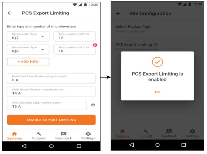
As the MPU avoidance configuration can only be enabled in the partial home backup mode, the installer has to first select the ‘Partial Home Backup’ configuration under ‘Select Backup Type’.Then, in the ‘PCS Export Limiting’ section, the installer is required to enter the type of micro-inverters (IQ7, IQ6) & the number of micro-inverters of each type. Along with this, the installer adds information on the rating of the main load panel busbar, the main service breaker rating & can also set the PCS Controlled Export Current Limit. If thisvalue is not set, the system auto-calculates the export current limit based on the 2017 NEC.
 |
 |
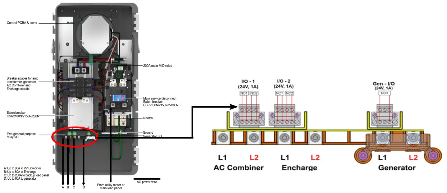
7. Auxiliary Contact ConnectionsEnpower has three I/O ports. I/O-1 has two normally open auxiliary contacts (NO1, NO2) and I/O-2 has two normally close auxiliary contacts (NC1, NC2) for load and excess PV control; each auxiliary contact has two terminals.Gen-I/O has one normally open auxiliary contact (NO3) for generator control, and this contact has three terminals. All the auxiliary contact relays are rated for pilot duty at 24Vac/Vdc (nominal) and 1 Amp.A. Auxiliary Contact connections for shedding excess PV and loadFor making the connections you would need the following components: a definite purpose contactor, control transformer, and fuse.For recommendations please refer to the tech briefhttps://support.enphase.com/s/article/Load-and-Solar-Circuit-Control-using-Enpower-Auxiliary-ContactsSteps for connecting auxiliary contact for shedding excess PV or load:
- Use wires sized per local code requirements taking into consideration the voltage drop/rise and upstream breaker or fuse.
- Connect one of the primaries of the control transformer to the 120V breaker, and the other wire to the neutral bus in the backup load panel via an OCPD such as an inline fuse.
- Connect one wire of the secondary of the control transformer to one of the terminals of either NO/NC auxiliary contact from I/O-1 or I/O-2 on Enpower.
- Connect the other terminal of the auxiliary contact to the 24Vac coil terminal (usually named A1) of the definite purpose contactor.
- Connect the other terminal of the contactor coil (usually named A2) to the other wire of the secondary of the control transformer.
- For shedding excess load:a. Connect the L1 (and L2 if 240V) terminal of the definite purpose contactor to the backup load panel protected by a breaker.b. Connect the T1 (and T2 if 240V) terminal of the contactor to the excess load circuit that needs to be shed.
- For shedding excess PV:a. Connect the L1 and L2 terminals of the definite purpose contactor to the OCPD (e.g., the breaker in the AC combiner) protecting the inverter output circuit of the excess PV to be shed.b. Connect the T1 and T2 terminals of the definite purpose contactor to the inverter output circuit of excess PV that needs to be shed.
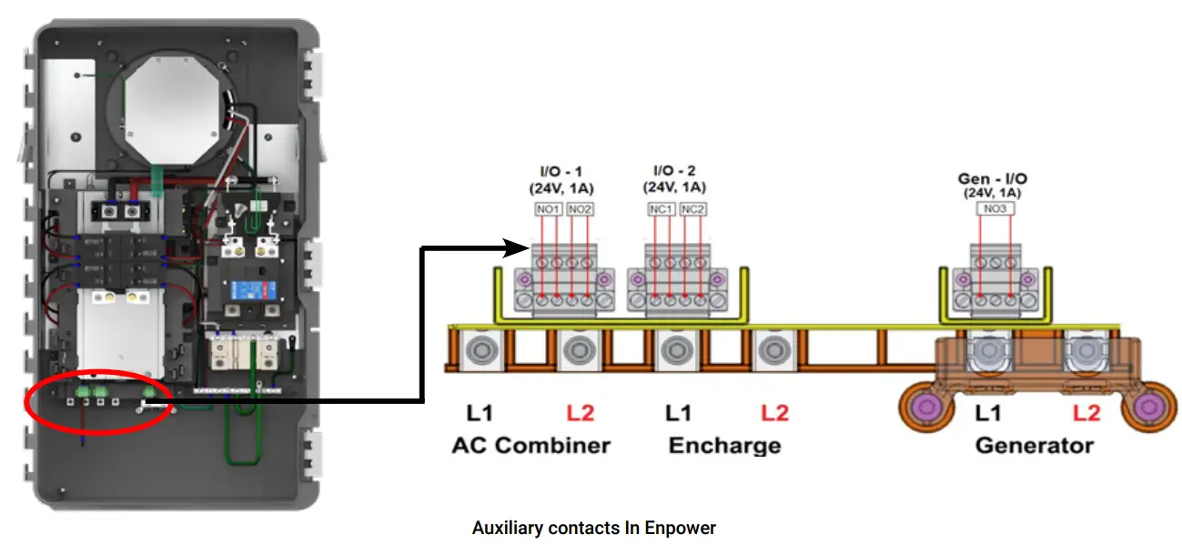
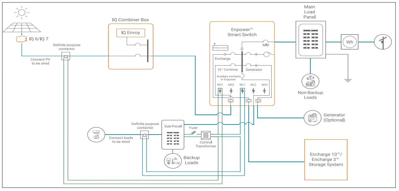
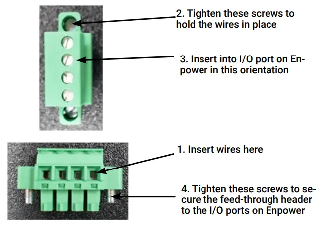
Line diagram for auxiliary contact connections used for shedding excess load and PV.Line diagram for auxiliary contact connections image shows NO1 is used to shed excess loads and NO2 is used to shed excess PV. See our technical brief, Load and Solar Circuit Control using Enpower Auxiliary Contacts (https://support.enphase.com/s/article/Load-and-Solar-Circuit-Control-using-Enpower-Auxiliary-Contacts),for detailed linediagram and other details.B. Securing Auxiliary Contact to EnpowerEnsure you have the feed-through headers that are shipped with the Enpower as part of the lit kit.Follow the below steps to secure the headers to Enpower, as shown in Feed through headers for I/0-1 and I/0-2 image.
- Insert the wires from the transformer controller and the external contactor into the feedthrough header.NOTE: Supports AWG 28 to AWG 16 wire sizes
- Tighten the screws on the top (torque 0.22Nm to 0.25Nm) to secure the wires.
- Insert the feedthrough header into the I/0-1 or I/0-2 ports on Enpower.
- Tighten the screws on the side to secure the feedthrough header to the I/0-1 or I/0-2 ports on Enpower.
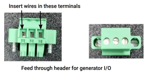
Follow the same procedure for Generator dry contact connections (There are 3 terminals on the Gen-I/0 port as shown in the Feed through header for generator I/O image. Use the first and third terminals for wiring.)
|
|
 |
 Feed through headers for I/O-1 and I/O-2
8. Generator ConnectionsA generator can be integrated with the Enphase Storage system without the need for any external ATS. It supports both manual and auto-start generators.NOTE: This system is only compatible with permanently installed generators that are non-separately derived as per NEC 250.35(B).Steps for connecting a generator are listed below:A ) Wire the L1 and L2 AC wires from the generator into the generator lugs on the Enpower.B ) Ensure that the ground terminal of the generator is connected to the ground bar inside Enpower. Size the generator’s equipment grounding conductor as per NEC 250.122 nd generator manufacturer’s instructions.C ) Connect the neutral wire from generator to an appropriately sized position on the neutral bar inside Enpower.NOTE: Enpower does not switch the neutral and the ground from the generator. It only switches the feeders i.e., L1 and L2.Therefore, the generator needs to be configured as a non-separately derived system.D ) Buy and install an appropriately sized breaker for the generator on the Enpower’s busbar and connect the L1 and L2 generator cables from Enpower’s ATS board to thisbreaker.NOTE: The maximum allowed breaker size is 60A. Select an Eaton BR breaker model that has the hole for the additional fastener as per NEC 480.36(D). Available models: R220B, BR230B, BR240B, BR250B. Eaton breaker BR260 already has the hole.E ) Purchase and install a hold-down screw kit (SKU: EP200G-NA-HD-200A) to secure the Generator breaker.F ) Install a pair of generator CTs (CT-200-SPLIT) for L1 and L2 at the Enpower’s Generator input terminal for power monitoring when the generator is running. Detailed CT wiring is described in step 9.G ) Use Enphase Installer Toolkit mobile application to commission and program Enpower to control the generator.H ) For 2-wire autostart generators, wire the Generator I/O port in Enpower to the 2-wire remote start terminals of the generator. Refer to Step 7 for steps on how to secure the auxiliary contacts to Enpower. Follow local code requirements for wire sizing.I ) Autostart generators typically require a constant 120 Vac for the battery charger. This power can be drawn from the backup load’s panel protected by a breaker so that it is powered even during an outage.J ) For autostart generators, have a certified contractor install the gas line required to supply the unit.K ) Some utility-sense-based generators like the Generac Eco-Gen come with the capability to auto-start generators when the system goes off-grid by sensing the absence of the 240V utility power. For such utility-sense-based remote start generators, install the utility sensing generator start/stop control circuit. Wire the primary of a 120V/12V power supply to the backup load’s panel. Connect the secondary to the Generator auxiliary contact relay on the Enpower. Wire the other end of the relay to the coil of the NormallyClose contactor. Connect the contactor to 240V from the backup load’s panel for utility sense. Wire the other end of the contactor to the Generator through a fuse.For more details, refer to the Technical Brief https://support.enphase.com/s/article/Generator-with-Enphase-storage
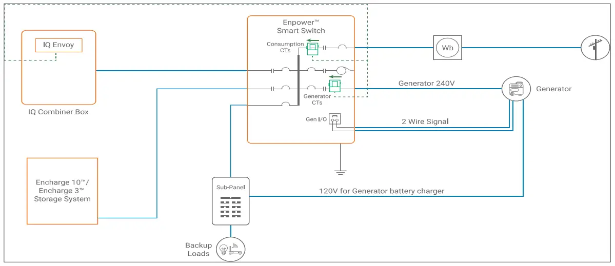
Line diagram for 2-wire remote start generator connection
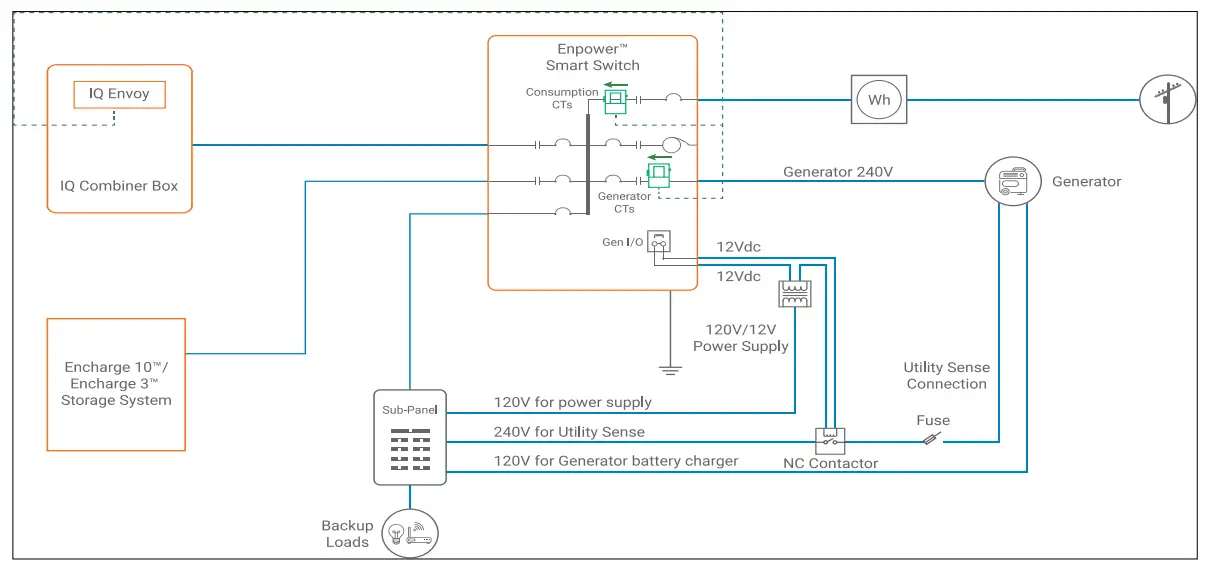
Line diagram for utility sense based remote start generator connection
 report this ad
9 Install the Generator CTs to standalone Envoy or Envoy in the Combiner boxA pair of generator CTs will be connected in parallel to the consumption CTs, if present.A ) Make sure that the main load center wires are de-energized until you have secured the CT wires in the terminal blocks.B ) Before running the CT wires through the conduit, use colored tape to mark one of the CTs and the free end of its wires.C ) Clamp the marked CT on Line 1 of the generator branch circuit inside the Enpower box with the arrow on the CT pointing towards the Generator breaker.D ) Clamp the unmarked CT on Line 2 of the generator branch circuit inside the Enpower box with the arrow pointing towards the Generator breaker.E ) Bring the CT lead wires out of Enpower to the standalone Envoy or Envoy in the Combiner boxF ) Use a screwdriver to loosen the screw on the Envoy terminal block door and open the door.G ) Unscrew the Consumption CT wires if presentH ) For the marked CTa. If the Consumption CT is present, use NEC approved wiring method to splice the white wire of the CT with the white wire of Line 1 of the consumption CT.b. Connect the spliced white wires to the upper “C1” terminal of IQ Envoy (“IA•” terminal for the Envoy-S Metered).c. Splice the blue wire of the CT with the blue wire of Line 1 of the consumption CT.d. Connect the spliced blue wires to the lower “C1” terminal of IQ Envoy (“IA” terminal for the Envoy-S Metered).I ) For the unmarked CTa. If the Consumption CT is present, use NEC approved wiring method to splice the white wire of the CT with the white wire of Line 2 of the consumption CT.b. Connect the spliced white wires to the upper “C2” terminal of IQ Envoy (“IB•” terminal for the Envoy-S Metered).c. Splice the blue wire of the CT with the blue wire of Line 2 of the consumption CT.d. Connect the spliced blue wires to the lower “C2” terminal of IQ Envoy (“IB” terminal for the Envoy-S Metered).J ) Tighten each of the Envoy terminal block screws to 5 in-lbs (0.56 Nm).K ) Close and secure the terminal block door of the Envoy.
10. Close and energize Enpower![]() WARNING: Before energizing, make sure that ALL Enpower connections are properly installed and conductors terminated.A ) Reconnect the deadfront ground cable to the grounding bar, torque as shown in the table on the unit label (and on page 4 of this guide), and replace the dead front using the six reserved screws. Tighten the cover screws using a Phillips screw driver.
WARNING: Before energizing, make sure that ALL Enpower connections are properly installed and conductors terminated.A ) Reconnect the deadfront ground cable to the grounding bar, torque as shown in the table on the unit label (and on page 4 of this guide), and replace the dead front using the six reserved screws. Tighten the cover screws using a Phillips screw driver.![]() WARNING! Risk of equipment damage. Ensure that no conductors are pinched before replacing the cover.
WARNING! Risk of equipment damage. Ensure that no conductors are pinched before replacing the cover.![]() WARNING! Conductors are factory provided for the generator, AC Combiner and Encharge. If no generator is used with the system, these conductors will not be terminated. If the Combiner does not connect to the Enpower, these will also not be terminated. When these wires are not terminated, they should remain stowed in the clips on the plastic frame supporting the panel board interior and their end caps should not be removed.
WARNING! Conductors are factory provided for the generator, AC Combiner and Encharge. If no generator is used with the system, these conductors will not be terminated. If the Combiner does not connect to the Enpower, these will also not be terminated. When these wires are not terminated, they should remain stowed in the clips on the plastic frame supporting the panel board interior and their end caps should not be removed.![]() DANGER: Risk of electric shock. There are many potential sources of voltage. Check any Enphase Encharge battery, PV, or another generation source for voltage.B ) You must ensure that all electrical circuits external to Enpower are completed and safe before energizing Enpower.C ) If you plan to energize Enpower without commissioning the system in the same day, OPEN the NFT and Encharge breakers and CLOSE the other breakers in the following order:
DANGER: Risk of electric shock. There are many potential sources of voltage. Check any Enphase Encharge battery, PV, or another generation source for voltage.B ) You must ensure that all electrical circuits external to Enpower are completed and safe before energizing Enpower.C ) If you plan to energize Enpower without commissioning the system in the same day, OPEN the NFT and Encharge breakers and CLOSE the other breakers in the following order:
- Main breaker
- PV breaker
- Generator breaker
- Load breaker.
NOTE: If not commissioning the system you must ensure that the DC switches on all Encharge batteries are turned off to avoid the depletion of charge on the Encharge batteries.D ) If you plan to commission the system, follow the instructions in the Enphase Installer Toolkit app for energizing Enpower.E ) Energize the circuit feeding the Enpower. If installed, turn the breaker feeding the Enpower to the on position.F ) Close and secure the door of the Enpower.11 Field Adjustable Trip PointsEnpower has adjustable voltage and frequency trip points that may need to be set depending upon local requirements. An installer can request Enphase Customer Support for making requested changes to the Enpower trip points. It is important to ensure that all electrical code requirements as well as requirements imposed by local Authorities HavingJurisdictions (AHJ) are followed while setting the trip points.CONFIGURE and ACTIVATEUse the Enphase Installer Toolkit to commission the Enpower. Once connected to the Envoy, refer to the Installer Toolkit help topics for more information.OPERATION If you do not see the Enpower information in Enlighten, check that the Envoy and the Internet connection are working.
SAFETY
IMPORTANT SAFETY INSTRUCTIONS. SAVE THESE INSTRUCTIONS. This guide contains important instructions that you must follow during the installation and maintenance of the Enphase Enpower. Failing to follow any of these instructions may void the warranty (enphase.com/warranty).In all cases:
- If safe to do so, switch off the AC breaker for the Enpower circuit, and if an isolator switch is present, switch off the AC isolator for the Enpower circuit.
- Contact the fire department or other required emergency response team.
- Evacuate the
In case of fire:
- When safe, use a fire Suitable types are A, B, and C dry chemical fire extinguishers. Additional extinguishing media include carbon dioxide, or alcohol-resistant foams.
In case of flooding:
- Stay out of water if any part of the Enpower or wiring is submerged.
- If possible, protect the system by finding and stopping the source of the water, and pumping it
- If water has contacted the UNIT, call your installer to arrange a inspection. If you are sure that water has never contacted the battery, let the area dry completely before
In case of unusual noise, smell, or smoke:
- Ensure nothing is in contact with the Enpower or in the venting area on top of the
- Ventilate the
- Contact Enphase Customer Support at enphase.com/en-us/support/contact.
Safety and Advisory Symbols![]() DANGER: This indicates a hazardous situation, which if not avoided, will result in death or serious injury.
DANGER: This indicates a hazardous situation, which if not avoided, will result in death or serious injury.![]() WARNING: This indicates a situation where failure to follow instructions may be a safety hazard or cause equipment malfunction. Use extreme caution and follow instructions carefully.✓NOTE: This indicates information particularly important for optimal system operation. Follow instructions carefully.Safety Instructions
WARNING: This indicates a situation where failure to follow instructions may be a safety hazard or cause equipment malfunction. Use extreme caution and follow instructions carefully.✓NOTE: This indicates information particularly important for optimal system operation. Follow instructions carefully.Safety Instructions![]() DANGER: Risk of electric shock. Risk of fire. Only qualified electricians should install, troubleshoot, or replace the Enpower.
DANGER: Risk of electric shock. Risk of fire. Only qualified electricians should install, troubleshoot, or replace the Enpower.![]() DANGER: Risk of electric shock. Risk of fire. Do not attempt to repair the Enpower. Tampering with or opening the Enpower will void the warranty.If the Enpower fails, contact Enphase Customer Support for assistance at enphase.com/en-us/support/contact.
DANGER: Risk of electric shock. Risk of fire. Do not attempt to repair the Enpower. Tampering with or opening the Enpower will void the warranty.If the Enpower fails, contact Enphase Customer Support for assistance at enphase.com/en-us/support/contact.![]() DANGER: Risk of electric shock. Do not use Enphase equipment in a manner not specified by the manufacturer. Doing so may cause death or injury to persons, or damage to equipment.
DANGER: Risk of electric shock. Do not use Enphase equipment in a manner not specified by the manufacturer. Doing so may cause death or injury to persons, or damage to equipment.![]() DANGER: Risk of electric shock. Do not install the Enpower without first removing AC power from the photovoltaic system and ensuring that the DC switch on the Enphase Encharge batteries is off. Disconnect the power coming from the photovoltaics and ensure that the DC switch on the Encharge batteries are off before servicing orinstalling.
DANGER: Risk of electric shock. Do not install the Enpower without first removing AC power from the photovoltaic system and ensuring that the DC switch on the Enphase Encharge batteries is off. Disconnect the power coming from the photovoltaics and ensure that the DC switch on the Encharge batteries are off before servicing orinstalling.![]() DANGER: Risk of electric shock. Risk of fire. Do not work alone. Someone should be in the range of your voice or close enough to come to your aid when you work with or near electrical equipment.
DANGER: Risk of electric shock. Risk of fire. Do not work alone. Someone should be in the range of your voice or close enough to come to your aid when you work with or near electrical equipment.![]() DANGER: Risk of fire. Do not allow or place flammable, sparking, or explosive items near the Enpower.
DANGER: Risk of fire. Do not allow or place flammable, sparking, or explosive items near the Enpower.![]() DANGER: Risk of electric shock. In areas where flooding is possible, install the Enpower at a height that prevents water ingress.
DANGER: Risk of electric shock. In areas where flooding is possible, install the Enpower at a height that prevents water ingress.![]() WARNING: Risk of equipment damage. Enpower is shipped and stored on its back. The upright position is only needed when installed.
WARNING: Risk of equipment damage. Enpower is shipped and stored on its back. The upright position is only needed when installed.![]() WARNING: You must install the Enpower only on a suitable wall using an Enphase wall-mount bracket.
WARNING: You must install the Enpower only on a suitable wall using an Enphase wall-mount bracket.![]() WARNING: Before installing or using the Enpower, read all instructions and cautionary markings in this guide and on the equipment.
WARNING: Before installing or using the Enpower, read all instructions and cautionary markings in this guide and on the equipment.![]() WARNING: Do not install or use the Enpower if it has been damaged in any way.
WARNING: Do not install or use the Enpower if it has been damaged in any way.![]() WARNING: Do not sit on, step on, place objects on, or insert objects into the Enpower.
WARNING: Do not sit on, step on, place objects on, or insert objects into the Enpower.![]() WARNING: Do not place beverages or liquid containers on top of the Enpower. Do not expose the Enpower to flooding.✓NOTE: Perform installation and wiring, including protection against lightning and resulting voltage surge, in accordance with all applicable local electrical codes and standards.✓NOTE: Because Encharge is grid forming, you must install signage in accordance with NEC articles 705, 706, and 710.✓NOTE: Using unapproved attachments or accessories could result in damage or injury.✓NOTE: Install properly rated over current protection as part of the system installation.✓NOTE: To ensure optimal reliability and to meet warranty requirements, the Enpower must be installed and/or stored according to the instructions in this guide.✓NOTE: The Enpower is compatible only with the IQ Envoy or Envoy S-metered communications gateway properly fitted with USB hub, USB radios, and production and Consumption/PCS CTs. The Envoy is required for operation of the Enpower. Earlier versions of the Enphase Envoy communications gateway are incompatible.✓NOTE: The Enphase Enpower is intended to operate with an Internet connection through the Envoy. Failure to maintain an Internet connection may have an impact on thewarranty. See Limited Warranty for full terms and services (enphase.com/warranty).✓NOTE: When replacing an Enphase Enpower, you must replace it with an Enpower of the same type, with the same AC current rating.✓NOTE: Properly mount the Enpower. Ensure that the mounting location is structurally suited to bearing the weight of the Enpower.✓NOTE: During use, storage, and transport, keep the Enpower:
WARNING: Do not place beverages or liquid containers on top of the Enpower. Do not expose the Enpower to flooding.✓NOTE: Perform installation and wiring, including protection against lightning and resulting voltage surge, in accordance with all applicable local electrical codes and standards.✓NOTE: Because Encharge is grid forming, you must install signage in accordance with NEC articles 705, 706, and 710.✓NOTE: Using unapproved attachments or accessories could result in damage or injury.✓NOTE: Install properly rated over current protection as part of the system installation.✓NOTE: To ensure optimal reliability and to meet warranty requirements, the Enpower must be installed and/or stored according to the instructions in this guide.✓NOTE: The Enpower is compatible only with the IQ Envoy or Envoy S-metered communications gateway properly fitted with USB hub, USB radios, and production and Consumption/PCS CTs. The Envoy is required for operation of the Enpower. Earlier versions of the Enphase Envoy communications gateway are incompatible.✓NOTE: The Enphase Enpower is intended to operate with an Internet connection through the Envoy. Failure to maintain an Internet connection may have an impact on thewarranty. See Limited Warranty for full terms and services (enphase.com/warranty).✓NOTE: When replacing an Enphase Enpower, you must replace it with an Enpower of the same type, with the same AC current rating.✓NOTE: Properly mount the Enpower. Ensure that the mounting location is structurally suited to bearing the weight of the Enpower.✓NOTE: During use, storage, and transport, keep the Enpower:
- Properly ventilated
- Away from the water, other liquids, heat, sparks, and direct sunlight
- Away from excessive dust, corrosive and explosive gases, and oil smoke
- Away from direct exposure to gas exhaust, such as from motor vehicles
- Away from falling or moving objects, including motor vehicles. If mounted in the path of a motor vehicle, we recommend a 91cm (36-inch) minimum mounting height
- In a location compliant with fire safety regulations
- In a location compliant with local building codes and standards
1 NOTE: Enpower is not suitable for use as service equipment in Canada.Environmental Protection ELECTRONIC DEVICE: DO NOT THROW AWAY. Waste electrical products should not be disposed of with household waste. Refer to your local codes for disposal requirements.Enphase Customer Support: enphase.com/en-us/support/contact
![]() © 2021 Enphase Energy. All rights reserved.Enphase, the Enphase logo, Enpower smart switch, Encharge storage system, IQ Envoy, IQ combiner, IQ microinverter, InstallerThe toolkit, Enlighten and other trademarks or service names are the trademarks of Enphase Energy, Inc.Data subjectto change.Rev04-09-27-2021
© 2021 Enphase Energy. All rights reserved.Enphase, the Enphase logo, Enpower smart switch, Encharge storage system, IQ Envoy, IQ combiner, IQ microinverter, InstallerThe toolkit, Enlighten and other trademarks or service names are the trademarks of Enphase Energy, Inc.Data subjectto change.Rev04-09-27-2021
References
[xyz-ips snippet=”download-snippet”]