QUICK INSTALL GUIDEModel number: EP200G101-M240US00
Install the Enphase Enpower Smart Switch
To install the Enphase Enpower™ smart switch and the Enphase Empower wall-mount bracket, read and follow all warnings and instructions in this guide and in the Enphase Empower Installation and Operation Manual at enphase.com/support. Safety warnings are listed on the back of this guide. These instructions are not meant to be a complete explanation of how to design and install an energy storage system. All installations must comply with national and local electrical codes and standards. Only qualified electricians shall install, troubleshoot, or replace the Empower.
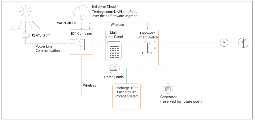
The Enphase Ensemble System includes the Enphase Enpower™ smart switch with Microgrid Interconnection Device (MID) capability, which consolidates interconnection equipment into a single enclosure and streamlines grid-independent capabilities of PV and storage installations by providing a consistent, pre-wired solution for residential applications. Along with MID functions, it includes PV, storage, and generator (reserved for future use¹) input circuits.
Four unique installation scenarios are shown:
Whole-home backup with Empower as service entrance and PV combiner connected to Empower. This is the preferred configuration for backup of the entire main load panel. This configuration supports up to an 80A breaker for the PV circuit and an 80A breaker for battery storage.
Whole-home backup with Empower as service entrance and PV combiner connected to main load panel. This is the preferred configuration when you back up the entire main load panel, and the size of the PV combiner circuit is more than 80A. In this configuration, the PV combiner circuit connection space in Empower is left vacant.When existing PV combiner circuits are connected to the main load panel, and you want to add battery storage to the system, you can keep the PV combiner connected to the main load panel and connect only the battery storage system to Empower.
Partial home backup with main load panels service entrance and PV combiner connected to Empower. When PV circuit breaker size is less than 80A, this is the preferred configuration for partial home backup with subpanel.
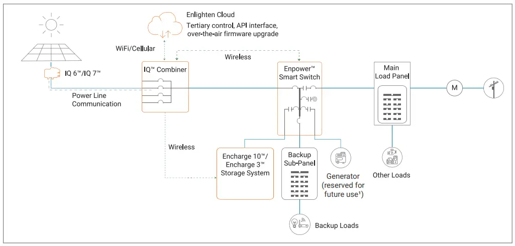
Partial home backup with main load panel as service entrance and PV combiner connected to subpanel. This is the preferred connection configuration for partial home backup using a subpanel when the PV circuit breaker size is more than 80A. The space available in Empower for combiner (solar) connection is left vacant.

PREPARATION
A ) Inspect the packaging and the Empower for damage. Do not install or use the Empower if it has been damaged in any way.B ) Ensure that you have the following:
- One Enphase Enpower smart switch. The Empower shipping box contains an Enphase Empower, mounting bracket, mounting hardware, and lit kit (bag with labels and accessories). Among the accessories are four-pin receptacles/dry contacts that will be used for controlling external power relays in the future and are not needed at present.
 WARNING: The Empower smart switch weighs 38.5 kg (85 lbs) and will require two persons to lift the unit.
C ) Make sure you have the following required items:
- Enphase Encharge™ storage system, which is required for off-grid applications.
- The Enphase Empower requires a wireless connection to an IQ Envoy, which requires an Internet connection. Failure to maintain an Internet connection may have an impact on the warranty. See enphase.com/warranty for full terms and services.
- Wireless USB Adapter (COMMS-KIT-01) to be installed at Envoy for communications with Encharge and Empower. Includes USB cable for connection to IQ Envoy / IQ Combiner and allows wireless communication with Encharge and Empower.
- Empower lifting handles (EP200G-HNDL-R1).
- Eaton BR Series breakers, rated maximum 80A for Encharge storage system and Enphase IQ™ combiner.
- If breakers are required at the input or output to Empower, use Eaton, Type CSR breakers rated 100 A, 125A, 150 A, 175A, or 200 A.
- Tools: conduit (with fittings and fitting tools), drill, 5/32 inch pilot bit (or metric equivalent), screwdriver, socket, wrench, adjustablewrench, torque wrench, level, 5/32 inch Allen key (or metric equivalent), conductor stripper, electrician’s hole saw (2 inches) kit or punch set, and stud finder if installing on studs.
- Conduit fittings (hubs) are required for all installations, and NEMA Type 3 conduit fittings (hubs) are needed when installing out ofdoors (one for each used conduit opening).
- Conduit ground hub rings.NOTE: Conduit entry is allowed only through the bottom or bottom sides of the unit.
- Three #10 lag bolts or screws, 7.6cm (three inches) long (depending on attachment wall), for each wall-mount bracket. Check with astructural engineer and local standards for local requirements.
- Washers for use between fastener heads and wall-mount bracket.
- Conductors rated at 75°C. For sizes, refer to the table on the unit and to local codes.
- Overcurrent protection: maximum in accordance with local standards.
- The door sheet metal is not required to be grounded, since it is protected from live parts by other grounded metal and insulating plastic materials, thus is considered unlikely to become energized.
INSTALLATION
Plan a location for the Empower
The Empower housing is NEMA type 3R and can be installed indoors or outdoors.A ) Follow all local codes and standards when planning for and installing the Enphase Empower Smart Switch.B ) Choose a well-ventilated location where the ambient temperature is within -40° C to 50° C (-40° F to 122° F), preferably out of directsunlight.C ) Ensure that the mounting location can sustain the weight of the Empower and mounting bracket 38.5 kg (85 lbs). The wall must include studs that can bear 38.5 kg (85 lbs) or can be of masonry or other suitable structure that can bear the weight.D ) Check the mounting location clearances:
- Indoors: at least 15cm (six inches) off the ground and 15cm (six inches) from the ceiling.
- Outdoors: at least 91cm (three feet) off the ground.
E ) Ensure that there are no pipes or electrical conductors where you plan to drill.F ) Plan to maintain at least 90cm (three feet) of clearance in front of the Empower.G ) Consider the dimensions of the Empower, easy access, unit height, conduit entry, and length of cable when selecting the location.H ) Select a location where you can interconnect to the site’s load center using the Enphase Empower.
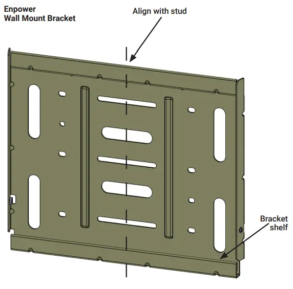
Install the wall-mount bracket
A ) Mark a plumb line over the wall stud as a guide.![]() WARNING! Multiple risks. Make sure not to drill or attach into electric wiring or pipes that are in the wall!B ) Remove the wall mount bracket only from the shipping box.C ) Place the wall-mount bracket on the wall so that the mounting holes in the middle of the bracket align with the center of the stud. Use a level to keep the bottom of the wall-mount bracket level. Use the wood screws (or masonry attachments if installing in masonry) to attach the bracket using one screw and washer for each slot.D ) Verify that the wall-mount bracket is level, solidly attached to the wall, and oriented for upright installation of the Empower.
WARNING! Multiple risks. Make sure not to drill or attach into electric wiring or pipes that are in the wall!B ) Remove the wall mount bracket only from the shipping box.C ) Place the wall-mount bracket on the wall so that the mounting holes in the middle of the bracket align with the center of the stud. Use a level to keep the bottom of the wall-mount bracket level. Use the wood screws (or masonry attachments if installing in masonry) to attach the bracket using one screw and washer for each slot.D ) Verify that the wall-mount bracket is level, solidly attached to the wall, and oriented for upright installation of the Empower.
![]() WARNING! Risk of injury and equipment damage. Do not mount an Empower on a bracket that is not properly attached to a wall.
WARNING! Risk of injury and equipment damage. Do not mount an Empower on a bracket that is not properly attached to a wall.![]() WARNING! Risk of injury and equipment damage. Protect the Empower from impact damage and improper use.
WARNING! Risk of injury and equipment damage. Protect the Empower from impact damage and improper use.
Unbox and Mount the Empower on the wall
![]() WARNING: Risk of injury. Take care when lifting. The Empower is heavy 38.5 kg (85 lbs).
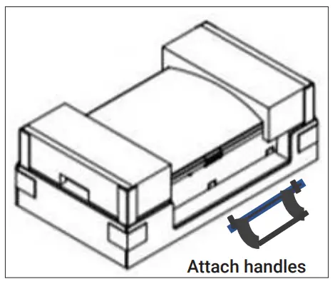
WARNING: Risk of injury. Take care when lifting. The Empower is heavy 38.5 kg (85 lbs).![]() WARNING! Risk of injury and equipment damage. Avoid dropping the Empower. Doing so may create a hazard, cause serious injury, and/ or damage the equipment.A ) Remove the upper Empower box, and locate the slots on both sides of the Empower enclosure.B ) Locate the lifting handles (sold separately) and check that the plungers are extended and ready to engage into the Empower slots.C ) Align one handle on one side of the Empower and press the handle into the slots, and slide the handle toward the top of the Empowerenclosure until it clicks into place. Check that the handle is secure.D ) Repeat on the other side with the second handle.
WARNING! Risk of injury and equipment damage. Avoid dropping the Empower. Doing so may create a hazard, cause serious injury, and/ or damage the equipment.A ) Remove the upper Empower box, and locate the slots on both sides of the Empower enclosure.B ) Locate the lifting handles (sold separately) and check that the plungers are extended and ready to engage into the Empower slots.C ) Align one handle on one side of the Empower and press the handle into the slots, and slide the handle toward the top of the Empowerenclosure until it clicks into place. Check that the handle is secure.D ) Repeat on the other side with the second handle.
![]() WARNING! Risk of injury and equipment damage. Two persons are required to lift the Empower.
WARNING! Risk of injury and equipment damage. Two persons are required to lift the Empower.
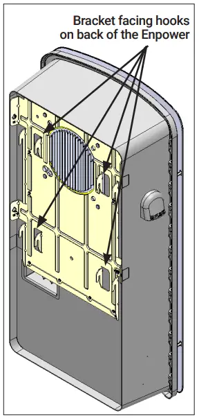
E ) Use the lifting handles, take the Empower from the packaging, making sure it is top side up (upright). Empower is designed only for vertical installation without inclination (must be level).F ) Lift the Empower slightly above the installed wall mount bracket and allow it to slide down so that the bracket facing hooks are set into both the top and bottom shelves of the wall mount bracket.G ) Allow the Enpower to slide down until the Enpower is fully seated on the wall-mount bracket shelf.![]() WARNING! Risk of injury and equipment damage. Do not release the Enpower until you ensure that the Enpower is fully seated in the wall-mount bracket shelf.H ) For each handle, pull the plunger tabs to release them and remove the lift handles.I ) Reserve the handles for the next installation.J ) On the bottom handle mounts, use the two provided partial-threaded custom M6 screws to secure each side of the Enpower and tighten to 0.5 N•m (4.4 lb•in) or less.
WARNING! Risk of injury and equipment damage. Do not release the Enpower until you ensure that the Enpower is fully seated in the wall-mount bracket shelf.H ) For each handle, pull the plunger tabs to release them and remove the lift handles.I ) Reserve the handles for the next installation.J ) On the bottom handle mounts, use the two provided partial-threaded custom M6 screws to secure each side of the Enpower and tighten to 0.5 N•m (4.4 lb•in) or less.
The threaded portion of the screw engages with the bracket, while the unthreaded portion of the screw engages with the hole in the bracket to prevent vertical movement of the bracket.![]() WARNING! Risk of injury and equipment damage. Do not skip this step. Without these screws in place, the Enpower may fall and cause injury or damage if bumped or shaken.K ) Use the four filler plates, provided in the lit kit, to cover the screws.
WARNING! Risk of injury and equipment damage. Do not skip this step. Without these screws in place, the Enpower may fall and cause injury or damage if bumped or shaken.K ) Use the four filler plates, provided in the lit kit, to cover the screws.
Install Breakers as Needed
The Enpower includes one two-pole 40A circuit breaker that feeds the neutral forming transformer (NFT). You can install additional breakers if needed. You must follow all NEC and local electrical codes.Install breakers as needed for the AC grid, main load, Enphase IQ Combiner, Enphase Encharge batteries, and generator (reserved forfuture use¹).These breakers are not included and must be ordered separately.NOTE: You must install a backup loads breaker if required by local code.NOTE: Generator connection is not currently supported. This feature will be supported in the future after an over-the-air software upgrade.![]() WARNING! Risk of injury and equipment damage. Use only the breakers listed in this table. Allowed breaker types include:
WARNING! Risk of injury and equipment damage. Use only the breakers listed in this table. Allowed breaker types include:
| Enphase Model No. | Type and Eaton part no. |
| BRK-100A-2P-240VBRK-125A-2P-240VBRK-150A-2P-240VBRK-175A-2P-240VBRK-200A-2P-240VBRK-20A-2P-240V-BBRK-30A-2P-240VBRK-40A-2P-240VBRK-60A-2P-240VBRK-80A-2P-240V |
|
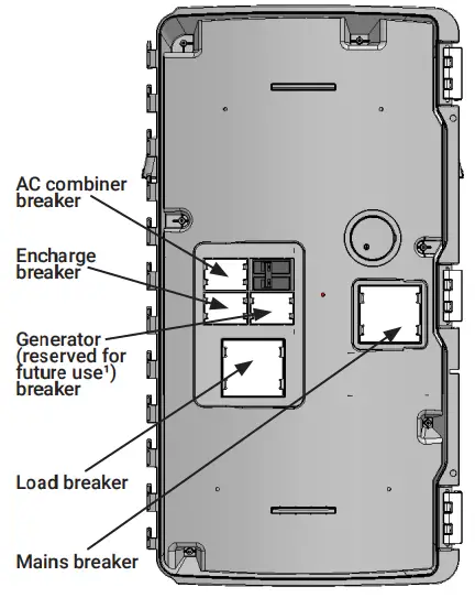
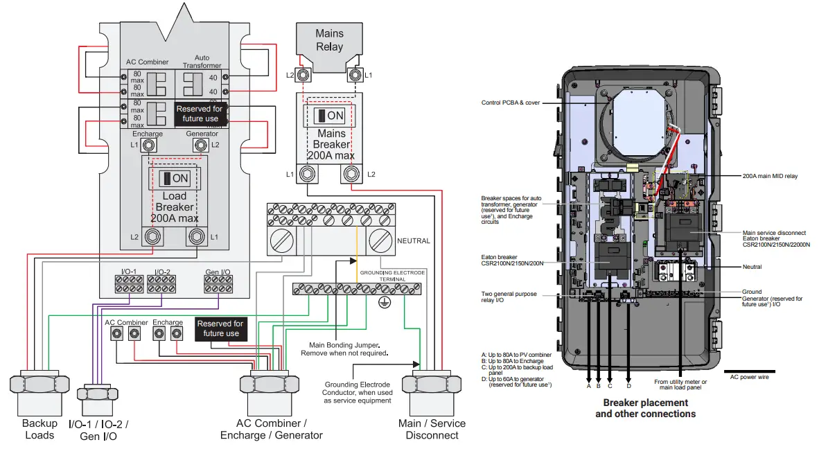
Breaker installation positions are noted in the diagram:
Required practices when torquing connections:
- Always follow NEC 2017 110.4 (D) dictates.
- You must use a calibrated torque tool to achieve the indicated torque values.
- Use tamper-proof torque mark/ paint after torquing connections.
| Connections | Wire size (AWG) | Torque (N•m / lb•in) |
| Main lugs Backup load lugs | Cu/AL: 300 KCMIL – 2 | 31.1 / 275 |
| CSR breakers | Cu/AL: 300 KCMIL – 2 | 28.2 / 250 |
| BR breakers (wire provided) | 6 | 3.1 / 27 |
| AC Combiner lugs, Recharge lugs, and Generator (reserved for future use¹) lugs | 14 – 1084 – 62 – 3 | 2.8 / 253.4 / 303.9 / 354.5 / 40 |
| Neutral – large lugs | Cu/AL: 300 KCMIL – 6 | 31.1 / 275 |
| Neutral and ground bars | ||
| Large holes (5/16-24 UNF) | 1/0 – 34 – 6810 -14 | 5.6 / 505.1 / 454.5 / 404.0 / 35 |
| Small holes (10-32 UNF) | 6 – 810 -14 | 2.8 / 251.7 / 15 |
A ) Ensure that the Enpower is completely de-energized.B ) Open the three latches that lock the enclosure door. To release the latch, pull the latch handle forward and then to the right. With all the latches opened, the swing opens the enclosure door.![]() WARNING: Risk of equipment damage. Do not remove the pre-installed solar shield attached to the enclosure door.C ) Use a Phillips screwdriver to loosen the six screws along the periphery of the dead front. Support the dead front to keep it from falling while performing the next step.D ) While supporting the dead front, use a screwdriver to disconnect the dead front ground wire from the grounding bar before the dead front is removed.E ) Use the two tabs on the front to assist in handling the dead front during the removal. Keep the dead front and screws handy as you will need them later.
WARNING: Risk of equipment damage. Do not remove the pre-installed solar shield attached to the enclosure door.C ) Use a Phillips screwdriver to loosen the six screws along the periphery of the dead front. Support the dead front to keep it from falling while performing the next step.D ) While supporting the dead front, use a screwdriver to disconnect the dead front ground wire from the grounding bar before the dead front is removed.E ) Use the two tabs on the front to assist in handling the dead front during the removal. Keep the dead front and screws handy as you will need them later.

![]() WARNING: Risk of electric shock. To maintain the warranty, do not modify the dead front other than to remove or replace filler plates, as needed.
WARNING: Risk of electric shock. To maintain the warranty, do not modify the dead front other than to remove or replace filler plates, as needed.
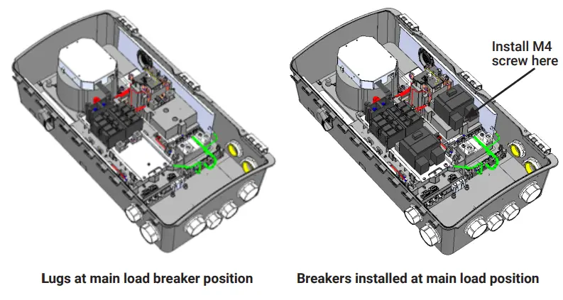
F ) If you install the main breaker or load breaker, remove the standard lugs before installing the Eaton CSR breaker. By default, lugs are provided in the Enpower unit for connection to the mains and to the load. In case of usage without breakers, the conductors are connected directly to these lugs. When breakers are used, the lugs are replaced with breakers during installation.G ) Remove a filler plate from the dead front for each breaker position you will use. Refer to the breaker position diagram to the left. To remove the filler plate, press the two snaps inward while gently pushing the filler plate out.H ) For the Recharge, AC Combiner or Generator (reserved for future use¹) connection, snap the appropriately sized BR series two-pole Eaton breaker onto the busbar, using only the breaker positions indicated in the diagram on the door of the unit. Breaker functional positions are not interchangeable with one another. The wires to be connected to each breaker are located beside each breaker position. Remove the heat shrink cap on the wire ends before inserting into the breaker.I ) Install each breaker by rocking it to the left, catching the clips that hold it in place. Then rock the breaker to the right so it is fully seated and secure.J ) For the main load breaker, use an appropriately sized CSR Eaton breaker. Install at the location indicated in the diagram on the door of the unit.K ) Remove the mains/load lugs by unscrewing the two nuts holding the lugs. Re-use the same nuts to fix the CSR breakers in the same position.L ) Use the M4 screw (from the lit kit marked 150-00148 that ships with the Enpower) to secure the mains breaker (not the load breaker). Use a T20 drive to tighten the M4 screw to 1.5 N•m (13.3 lb•in). Do not use any other screw.M ) Check that all breakers are properly seated.N ) Torque the breaker connections as listed in the following and in the conductor table on the unit.O ) Purchase and install an Eaton type BR circuit breaker hold-down screw kit (model BRHDK125) to secure only the Encharge and generator (reserved for future use¹) double-pole circuit breaker(s). Refer to https://www.homedepot.com/p/Eaton-Type-BR-Hold-Down-Bolting-Screw-Kit-BRHDK125/100193360 for installation information and specifications.
Wire the Field Connections
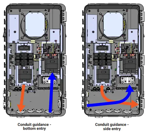
A ) Drill conduit entry holes as needed, and install conduit grounding lugs for each opening. Be sure to reseal unused conduit entry holes with sealing plugs.NOTE: Main supply conductors may enter the Enpower from the bottom or from the bottom-left side. Backup load conductors may enter the Enpower from the bottom or bottom-right side. Anchorage, Combiner, and generator (reserved for future use¹) conductors may enter from the bottom, bottom-left, or bottom-right sides.B ) Size the conductors (Line, Neutral, and Ground) depending on the breaker or fuse, proper ampacity, and voltage rise requirements according to local codes.Refer to the conductor rating table on the door of the Enpower.![]() DANGER! Risk of electric shock. Check that all circuits connecting to the Enpower are de-energized before wiring.C ) If the Enpower is not installed at service equipment², you must remove the main bonding jumper connected between the grounding bar and the neutral assembly. Refer to the wiring diagram.NOTE: Do not modify or rewire any of the other pre-installed wiring or bonding connections in the Enpower.D ) If Enpower is installed as service equipment²:
DANGER! Risk of electric shock. Check that all circuits connecting to the Enpower are de-energized before wiring.C ) If the Enpower is not installed at service equipment², you must remove the main bonding jumper connected between the grounding bar and the neutral assembly. Refer to the wiring diagram.NOTE: Do not modify or rewire any of the other pre-installed wiring or bonding connections in the Enpower.D ) If Enpower is installed as service equipment²:
- Connect a grounding electrode conductor to the grounding bar.
- From the lit kit, place the label “GROUNDING ELECTRODE TERMINAL” adjacent to the grounding bar.
- From the lit kit, place the label “SUITABLE FOR USE AS SERVICE EQUIPMENT” / “MAIN SERVICE DISCONNECT” on the dead front near the main breaker/ service disconnect.
- If Enpower is not used as service equipment, these labels should not be used.
E ) Connect Lines, Neutral, and Ground. For details, refer to the conductor table on the unit for sizes and refer to local codes.![]() WARNING! Risk of equipment damage. Always connect to two Lines (active), one neutral, and one ground.F ) Use the included stowed conductors, as labeled, to wire the circuit breaker(s) for the Recharge batteries, Enphase Combiner, and generator (reserved for future use¹), as needed. The stowed conductors are provided with crimped-on ferrules with end caps to prevent accidental contact. Remove the conductor end caps as needed.G ) Torque the breaker connections as listed on the previous page and in the conductor the table on the unit.H ) After all conductors are connected and secured, check that there are no exposed conductors or stray wires.I ) Gently arrange all the conductors and connectors inside the cabinet.
WARNING! Risk of equipment damage. Always connect to two Lines (active), one neutral, and one ground.F ) Use the included stowed conductors, as labeled, to wire the circuit breaker(s) for the Recharge batteries, Enphase Combiner, and generator (reserved for future use¹), as needed. The stowed conductors are provided with crimped-on ferrules with end caps to prevent accidental contact. Remove the conductor end caps as needed.G ) Torque the breaker connections as listed on the previous page and in the conductor the table on the unit.H ) After all conductors are connected and secured, check that there are no exposed conductors or stray wires.I ) Gently arrange all the conductors and connectors inside the cabinet.![]() DANGER! Risk of electric shock. The system is not ready to be energized! Do not close any circuit breaker yet.NOTE: The polarity of L1 and L2 is swapped inside the Eaton CSR series main breakers.Installers should follow L1 and L2 on the following image when installing consumption CTs.
DANGER! Risk of electric shock. The system is not ready to be energized! Do not close any circuit breaker yet.NOTE: The polarity of L1 and L2 is swapped inside the Eaton CSR series main breakers.Installers should follow L1 and L2 on the following image when installing consumption CTs.
Close and Energize Enpower
![]() WARNING: Before energizing, make sure that ALL Enpower connections are properly installed and conductors terminated.A ) Reconnect the dead front ground cable to the grounding bar, torque as shown in the table on the unit label (and on page 4 of this guide),and replace the dead front using the six reserved screws. Tighten the cover screws using a Phillips screwdriver.
WARNING: Before energizing, make sure that ALL Enpower connections are properly installed and conductors terminated.A ) Reconnect the dead front ground cable to the grounding bar, torque as shown in the table on the unit label (and on page 4 of this guide),and replace the dead front using the six reserved screws. Tighten the cover screws using a Phillips screwdriver.![]() WARNING! Risk of equipment damage. Ensure that no conductors are pinched before replacing the cover.
WARNING! Risk of equipment damage. Ensure that no conductors are pinched before replacing the cover.![]() WARNING! Conductors are factory provided for the generator (reserved for future use¹), AC Combiner, and Recharge. If no generator is used with the system, these conductors will not be terminated.
WARNING! Conductors are factory provided for the generator (reserved for future use¹), AC Combiner, and Recharge. If no generator is used with the system, these conductors will not be terminated.
If the Combiner does not connect to the Enpower, these also will not be terminated. When these wires are not terminated, they should remain stowed in the clips on the plastic frame supporting the panel board interior and their end caps should not be removed.![]() DANGER: Risk of electric shock. There are many potential sources of voltage. Check any Enphase Encharge battery, PV, or another generation source for voltage. B ) You must ensure that all electrical circuits external to Enpower are completed and safe before energizing Enpower in the followingorder:
DANGER: Risk of electric shock. There are many potential sources of voltage. Check any Enphase Encharge battery, PV, or another generation source for voltage. B ) You must ensure that all electrical circuits external to Enpower are completed and safe before energizing Enpower in the followingorder:
- NFT breaker
- Main breaker
- PV breaker
- Recharge breaker
- Generator (reserved for future use¹) breaker
- Load breaker.
C ) Energize the circuit feeding the Enpower. If installed, turn the breaker feeding the Enpower to the on position.D ) Close and secure the door of the Enpower.7 Field Adjustable Trip PointsNOTE: Enpower has field-adjustable voltage and frequency trip points that may need to be set, depending upon local requirements. Only an authorized installer with the permission and following requirements of the local electrical authorities should make adjustments.
CONFIGURE and ACTIVATE
Use the Enphase Installer Toolkit to commission the Enpower. Once connected to the Envoy, refer to the Installer Toolkit help topics for more information.
OPERATION
If you do not see the Enpower information in Enlighten, check that the IQ Envoy and the Internet connection are working.
SAFETY
IMPORTANT SAFETY INSTRUCTIONS. SAVE THESE INSTRUCTIONS. This guide contains important instructions that you must follow during the installation and maintenance of the Enphase Enpower. Failing to follow any of these instructions may void the warranty (enphase.com/warranty).
In Case of Fire or Other EmergencyIn all cases:
- If safe to do so, switch off the AC breaker for the Enpower circuit, and if an isolator switch is present, switch off the AC isolator for the Enpower circuit.
- Contact the fire department or other required emergency response team.
- Evacuate the area.
In case of fire:
- When safe, use a fire extinguisher. Suitable types are A, B, and C dry chemical fire extinguishers. Additional extinguishing media include carbon dioxide or alcohol-resistant foams.
In case of flooding:
- Stay out of the water if any part of the Enpower or wiring is submerged.
- If possible, protect the system by finding and stopping the source of the water, and pumping it away.
- If water has contacted the UNIT, call your installer to arrange an inspection.If you are sure that water has never contacted the battery, let the area dry completely before use.
In case of unusual noise, smell or smoke:
- Ensure nothing is in contact with the Enpower or in the venting area on top of the Enpower.
- Ventilate the room.
- Contact Enphase Customer Support at enphase.com/en-us/support/contact.
Safety and Advisory Symbols
 |
DANGER: This indicates a hazardous situation, which if not avoided, will result in death or serious injury. |
| WARNING: This indicates a situation where failure to follow instructions may be a safety hazard or cause equipment malfunction. Use extreme caution and follow instructions carefully. | |
| √ | NOTE: This indicates information particularly important for optimal systemoperation. Follow instructions carefully. |
Safety Instructions
|
DANGER: Risk of electric shock. Risk of fire. Only qualified electricians should install, troubleshoot, or replace the Enpower. |
|
DANGER: Risk of electric shock. Risk of fire. Do not attempt to repair the Enpower. IT HAS NO SERVICEABLE PARTS. Tampering with or opening the Enpower will void the warranty. If the Enpower fails, contact Enphase Customer Support for assistance at enphase.com/en-us/support/contact. |
|
DANGER: Risk of electric shock. Do not use Enphase equipment in a manner not specified by the manufacturer. Doing so may cause death or injury to persons or damage to equipment. |
|
DANGER: Risk of electric shock. Do not install the Enpower without first removing AC power from the photovoltaic system and ensuring that the DC switch on the Enphase Encharge batteries are off. Disconnect the power coming from the photovoltaics and ensure that the DC switch on the Encharge batteries are off beforeservicing or installing. |
|
DANGER: Risk of electric shock. Risk of fire. Do not work alone. Someone should be in the range of your voice or close enough to come to your aid when you work with or near electrical equipment. |
|
DANGER: Risk of fire. Do not allow or place flammable, sparking, or explosive items near the Enpower. |
|
DANGER: Risk of electric shock. In areas where flooding is possible, install the Enpower at a height that prevents water ingress. |
 |
WARNING: Risk of equipment damage. Enpower is shipped and stored on its back. The upright position is only needed when installed. |
|
WARNING: You must install the Enpower only on a suitable wall using an Enphase wall-mount bracket. |
|
WARNING: Before installing or using the Enpower, read all instructions and cautionary markings in this guide and on the equipment. |
|
WARNING: Do not install or use the Enpower if it has been damaged in any way. |
|
WARNING: Do not sit on, step on, place objects on, or insert objects into the Enpower. |
Safety Instructions continued
|
WARNING: Do not place beverages or liquid containers on top of the Enpower. Do not expose the Enpower to liquids or flooding. |
| √ | NOTE: Perform installation and wiring, including protection against lightning and resulting voltage surge, in accordance with all applicable local electrical codes and standards. |
| √ | NOTE: Because Encharge is grid forming, you must install signage in accordance with NEC articles 705, 706, and 710. |
| √ | NOTE: Using unapproved attachments or accessories could result in damage or injury. |
| √ | NOTE: Install properly rated overcurrent protection as part of the system installation. |
| √ | NOTE: To ensure optimal reliability and to meet warranty requirements, the Enpower must be installed and/or stored according to the instructions in this guide. |
| √ | NOTE: The Enpower is compatible only with the IQ Envoy communications gateway properly fitted with a USB hub, USB radios, and production and consumption CTs.The IQ Envoy is required for the operation of the Enpower.Earlier versions of the Enphase Envoy communications gateway are incompatible. |
| √ | NOTE: The Enphase Enpower is intended to operate with an Internet connection through the Envoy.Failure to maintain an Internet connection may have an impact on the warranty. See Limited Warranty for full terms and services (enphase.com/warranty). |
| √ | NOTE: When replacing an Enphase Enpower, you must replace it with an Enpower of the same type, with the same AC current rating. |
| √ | NOTE: Properly mount the Enpower. Ensure that the mounting location is structurally suited to bearing the weight of the Enpower. |
| √ | NOTE: During use, storage, and transport, keep the Enpower:• Properly ventilated• Away from the water, other liquids, heat, sparks, and direct sunlight• Away from excessive dust, corrosive and explosive gases, and oil smoke• Away from direct exposure to gas exhaust, such as from motor vehicles• Away from falling or moving objects, including motor vehicles. If mounted in the path of a motor vehicle, we recommend a 91cm (36-inch) minimum mounting height• In a location compliant with fire safety regulations• In a location compliant with local building codes and standards |
| √ | NOTE: While Enpower provides the capability for connection of a generator, it does not presently support use with generators. Do not attempt to connect a generator until Enpower is ready to support a generator. This functionality is reserved for future use and will require an upgrade process to be followed by a qualified electrician. |
| √ | NOTE: Enpower is not suitable for use as service equipment in Canada. |
Environmental Protection ELECTRONIC DEVICE: DO NOT THROW AWAY. Waste electrical products should not be disposed of with household waste.Refer to your local codes for disposal requirements.
Enphase Customer Support: enphase.com/en-us/support/contact
 report this ad
© 2020 Enphase Energy. All rights reserved. Enphase, the Enphase logo, Enpower smart switch, Recharge storage system, IQ Envoy, IQ combiner, IQ microinverter, Installer Toolkit, Enlighten, and other trademarks or service names are the trademarks of Enphase Energy, Inc. Data subject to change. 2020-06-16
References
[xyz-ips snippet=”download-snippet”]