![]()
SMART HOME SECURITYWireless Solar Siren Alarm Kit (Red Lens)SL2KITAInstruction Manual![]()
Customer Helpline0345 257 2500
Model: SL2KITASee separate Keypad Instruction Manual KP700
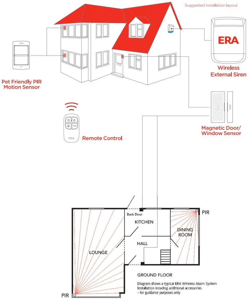
Suggested Installation/Layout
ERA Home SecurityValiant Way, Wolverhampton, West Midlands, WV9 5GBemail: [email protected] T: 0345 257 2500 www.responseelectronics.com
Customer Helpline 0345 257 2500Model: SL2KITA See separate Keypad Instruction Manual KP700
Kit Contents
Solar Siren x 1Pet-Friendly PIR Motion Sensor x 1Door/Window Magnetic Sensor x 1Remote Control x 1All Batteries and FixingsInstructions
LED Indication
Flashes every 2 seconds: self-testing stateFlashes twice: self-testing is finished, enters a working model.Flashes once: movement is detectedFlashes once every 3 seconds: low battery indication (immediate battery change required).
Before Installation,
a. Read the instructions thoroughly.b. Remove the contents from their packaging.c. Consider the most appropriate positioning.d. Avoid mounting the Sensor near metal objectsor electrical wiring.
PCB Layout
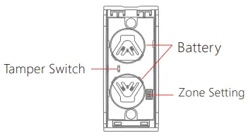
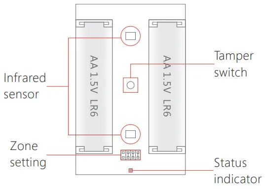 Infrared Sensor: Detects movement and triggers an alarm signal when the system is armed.Tamper Switch: If the casing is opened when in ‘working state’, the tamper switch will be triggered and generate an alarm signal.
1. PIR Motion Sensor
Two Lens PIR: pet tolerant to 25 kgs.Vertical and horizontal detection range 8m/110°.Automatic temperature compensation and anti-air turbulence technology/control: automatically adapt to environmental changes, thereby saving energy.
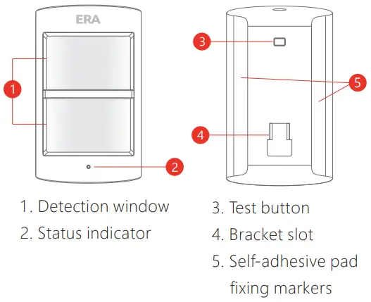
Appearance
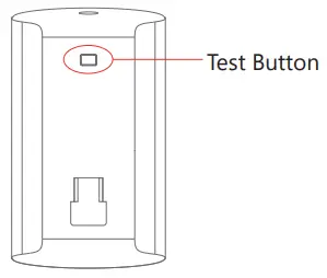
Test Mode
- Remove the activation strip. Fit the retaining screw supplied.
- Self-testing will commence for 1 minute as indicated by the LED flashing every 2 seconds.
- To enter Test Mode press the Test Button at the back of the PIR. The LED will then flash once when movement is detected, for up to 3 minutes.
Working Mode
- To test in Working Mode, walk in front of the Sensor – the LED should illuminate once when movement is detected.
- If the Sensor is triggered twice in 3 minutes it will enter into power saving (sleep mode). If no movement is detected within the next 3 minutes, the Sensor will return to normal working mode.
Installation
- Avoid mounting the Sensor in areas where draughts may be present or where the temperature may fluctuate greatly, such as near windows, air conditioning, heating, refrigeration units, cooking appliances, and direct sunlight.
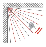
- Where possible, mount the Sensor in the corner of the room so that the logical path of an intruder would cut across the fan detection pattern. A PIR responds more effectively to movement across the device than to movement directly towards it.
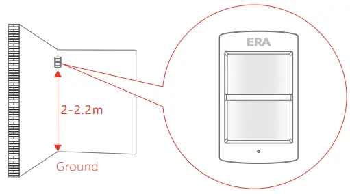
- Fit the Sensor in a position that will cover your desired protection area:a. Fix the bracket to the wall with the fixings kit supplied. For optimum performance set the height of the bracket to 2 meters above ground level.b. Adjust the angle of the PIR Sensor to cover the required detection area.
 |
 To perform a walk test. Press the test button once and walk from left to right in the room. The LED indicator will flash once when motion is detected. To perform a walk test. Press the test button once and walk from left to right in the room. The LED indicator will flash once when motion is detected. |
Specification
| Power Supply | 2 x DC 1.5V AA Batteries |
| Static Current | ≤ 50uA |
| Alarm Current | ≤ 9.5mA |
| Detection Area | 8m/110° |
| Transmitting Distance Pet Immunity | ≤ 80m (in open area) |
| Pet Immunity | ≤ 25kg |
| Radio Frequency | 433 MHz |
| Housing Material | ABS Plastic |
| Operating Temperature | -10°C~55°C |
| Relative Humidity | ≤ 80% (non-condensing) |
| PIR Sensor Dimensions(L x W x D) | 100 x 59 x 43 mm |
| Bracket Dimensions(L x W x D) | 52 x 30 x 26.5 mm |
2. Door/Window Sensor
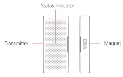
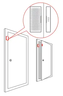
The Door/Window Sensor comprises a transmitter and a magnet. The Sensor can be mounted on doors, windows, and any other objects that can be opened or closed. When the transmitter and magnet are separated by more than 2cm, the Sensor will send a signal to the Control Panel to trigger an Alarm.
Appearance
LED Indication
Flashes once: door/window opened, the transmitter sends the signal to the Control Panel/SirenFlashes every 3 seconds: low battery indication (immediate battery change required)
PCB Layout
Installation
- Carefully remove the activation strip from the battery compartment.
- Remove the backing paper from one side of each self-adhesive double-sided strip. Fix one strip to the back of the Magnet and one to the back of the Transmitter.
- Peel off the other side of each adhesive strip. Mount the magnet on the door and the Transmitter on the door frame (small triangles facing each other), with less than a 1 cm separation between the two.
- When opening the door a small red indicator lights up briefly, this indicates that the Transmitter has sent a signal to the Control Panel.
 Specification
 Specification
| Power Supply | 2 x DC 3V Lithium Batteries (CR2032) | ||
| Static Current | ≤35uA | Alarm Current | ≤1 40mA |
| Transmitting Distance | s 80m (in open area) | ||
| Radio Frequency | 433 MHz | ||
| Housing Material | ABS Plastic | ||
| Operating Temperature | 0°C-55°C | ||
| Relative Humidity | ≤80% (non-condensing) | ||
| Sensor Dimensions (L x W x D) | 71x 31.5 x 15 mm | ||
| Magnet Dimensions (L x W x D) | 71x 12.5 x 15 mm |
Appearance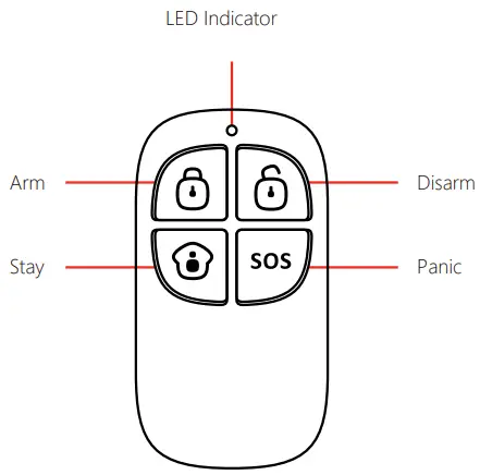 FeaturesThe Remote Control enables you to quickly and conveniently Arm and Disarm your Alarm System.In the event of an emergency (when in or near your property), pressing the SOS button will trigger an alarm condition on the Control Panel/Siren.
LED Indication
Flashes once: transmits the signalLow Light Level: low battery indication, (immediate battery change recommended)
Remote Control Buttons/Functions
See over.
Specification
| Power Supply | 1 x DC 3V (CR2025) Lithium Battery |
| Transmitting Distance | s80m (in open area) |
| Radio Frequency | 433 MHz |
| Housing Material | ABS Plastic |
| Operating Temperature | 0°C-50°C |
| Relative Humidity | _s 80% (non-condensing) |
| Dimensions (L x W x D) | 58 x 31 x 9.5mm |
Remote Control Buttons/Functions
|
Arm |
Press to Arm the Control Panel/Siren and all of the Accessories (Full Arm) |
|
|
Disarm |
Press to Disarm the System | |
|
Part Arm(Home Arm) |
Press to Part Arm the System (for Control Panel Systems only) | |
|
Panic |
Press to activate a Panic Alarm (SOS). The Control Panel will auto-dial out to the pre-set phone numbers immediately | |
|
Mute Arm |
Press to Arm the System with the Solar Siren in Mute/Silent Mode | |
| Mute Disarm |
Press to Disarm the System with the Solar Siren in Mute/Silent Mode |
Positioning
Install the Siren to the outside of the building in a position that is clearly visible and at a height that is relatively inaccessible to an intruder.The Siren is designed to work on any aspect wall, however for optimum performance try to avoid installing on a North facing wall or to a wall with shadows cast by other buildings, trees, and roof overhangs.For optimum radio signal reception mount the Solar Siren at a minimum distance of one meter away from any external or internal metalwork (drainpipes, gutters, radiators, etc).
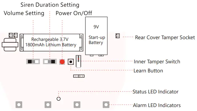
PCB Layout

Jumper Setup
Volume Setting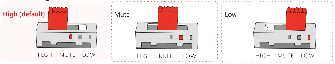
Siren Duration Setting
Usage
Important: connect the 9V Battery and press the Power on/off button prior to installation.
Connecting Wireless Accessories to the Siren
- Press the Learn Button on the Solar Siren (0.5 seconds), the system goes into Learn Mode after one beep is heard.
- Press the Test Button on the Accessory or trigger the Accessory once.
- The Wireless Accessory is learned successfully after a second beep.
- If two beeps are heard, the accessory is already linked.
- To finish learning the Accessories, press the Learn Button on the Siren again to exit Learn Mode after one beep.
The `Arm’ button will arm the siren with a 15-second exit delay. Sensors on the `single delay zone’ will have an entry delay of 15 seconds before the alarm sounds (unless disarmed by the Remote Control during the delay period).Sensors on the `normal zone’ will activate the alarm without a delay, i.e the Siren will sound immediately.The Siren will sound and the strobe light will flash upon activation of a connected Accessory.Disarm the system to stop the siren from sounding. If not disarmed the Siren status indicator will flash once every 2 seconds for one hour (visual notification of an alarm event).
Installation
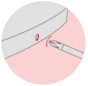 Remove the fixing screw from the bottom edge of the Siren housing and carefully remove the front cover. Remove the fixing screw from the bottom edge of the Siren housing and carefully remove the front cover. |
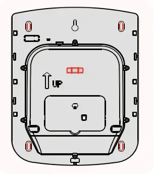 Hold the mounting plate in position and mark the positions of the four mounting holes. There is a Spirit Level inside the case to help ensure that the Siren is level. Hold the mounting plate in position and mark the positions of the four mounting holes. There is a Spirit Level inside the case to help ensure that the Siren is level. |
| Drill four holes in the wall and insert the wall plugs. Insert the screws through the backplate holes and screw them into the wall plugs. |
 Hinge the front cover locating tabs over the top edge of the backplate and carefully push the base of the siren cover into place. Secure the siren cover byrefitting the fixing screw in the bottom edge of the cover. Hinge the front cover locating tabs over the top edge of the backplate and carefully push the base of the siren cover into place. Secure the siren cover byrefitting the fixing screw in the bottom edge of the cover. |
Test Mode
- Test Mode prevents the Siren’s tamper switch from triggering an alarm during maintenance or when changing the battery.
- When the Remote Control is connected with the Siren, press Unlock 3 times (within 5 seconds) to enter Test Mode, the Siren will emit a long beep indicating that the system is now in Test Mode. During this period the Siren will not alarm but will beep if the tamper switch or the connected Sensors are triggered.
- Press Lock on the Remote Control to exit Test Mode after a short beep.
- The System is now Armed. Press Unlock to Disarm the System.
Enter/Exit Learning Status using a connected Remote Control
- If the Siren has been fitted as a standalone system, additional Accessories can easily be learned to the Siren without the need to dismount the Siren from the wall, as follows:
- Press Unlock on the Remote Control 3 times (within 5 seconds) to enter Test Mode.
- Press Home Arm 3 times (within 5 seconds) to enter Learn Mode. A long beep is heard from the Siren indicating that it is in Learn Mode. Press the Test Button on the additional Accessory or trigger the Accessory once.
- The Siren will beep again to indicate that the Accessory has been successfully connected with the Siren.
- Press Lock on the Remote Control to exit Learn Mode, it will emit one beep.
- The System is now Armed, press Unlock to Disarm the System.
Specifications
Back-up Power: 3.7V 1800mAh Rechargeable Lithium BatteryStart-up Power: 9V Alkaline BatterySolar Panel Output Current: 2000LUX illumination≥ 4mA (in sunlight)Maximum Alarm Current: ≤500mAWireless Receiving Distance: ≤80m (free space)Operating Conditions: Temperature -10°C ~ +55°CRelative Humidity ≤80% (non-condensing)Maximum Siren Volume: ≤110dBStandby Current: 1. mA Standby Time: ≤45 days (no sunlight)Wireless Receiving Frequency: 433MHzHousing Material: PC + ABS + ANTI-UVSize: 309 x 230 x 79.7mm
PRODUCT GUARANTEE *
We at ERA firmly believe in the quality of our goods. Our technology achieves outstanding performance and durability and we can therefore offer, in addition to your statutory rights, an additional limited guarantee. In the event of any material defects in any product manufactured by us due to faulty design, materials, and/or workmanship, and which arise following correct installation and during normal use in accordance with our instructions, as included in the product packaging, within the period of two years from the date of purchase, we will either repair, provide a replacement, substitute with an equivalent product free of charge from our then current range or refund in full the amount paid for the product at the point of purchase.
Conditions
In order to take advantage of our guarantee, you must comply with the following conditions:
- This limited guarantee is not transferable and is extended only to, and is solely for the benefit of, the original purchaser of the product. Please retain your dated sales invoice as proof of purchase and forward this to us if you wish to make a claim under this guarantee.
- Products must be installed, used, and maintained in accordance with our instructions otherwise the guarantee will be invalidated.
- The product must not be damaged or modified in any way nor must it have been subjected to any unauthorized repairs.
Exclusions This guarantee does not cover:
- Periodic maintenance, repair, and replacement of parts due to fair wear and tear.
- Abuse or misuse, including but not solely limited to the failure to use this product for its normal purposes or in accordance with ERA’s instructions on usage and maintenance.
- Failure of the product arising from incorrect installation or use is not consistent with the instructions supplied and the cost of any removal or installation of products.
- Accidents, Acts of God, lightning, water, fire, public disturbances, improper ventilation, voltage fluctuations, or any cause beyond the control of ERA (Force Majeure).
- Unauthorized modifications are carried out to the product.
- Damage caused by incorrect/improper use of supplied batteries.
- Alteration to, deletion, removal, or illegibility of the Serial Number as shown on the Product Label.
- Consumables: any damages so caused by the use of batteries not supplied by ERA.
- Repair or attempted repairing by bodies who are not ERA authorized repairers.
- Neglect.
The loss of any stored data on your product.This guarantee is in addition to your contractual and statutory rights and does not affect your statutory rights
To make a claim
Please contact Customer Support either by telephone on 0345 257 2500 or email [email protected] with full details of your claim. If your claim satisfies our Conditions and is not subject to any of our Exclusions, we will agree with you the repair, replacement, substitution, or refund of payment of goods. For product returns, you will be issued with a Return Authorisation Number (RAN). Please note: Returns will not be accepted unless accompanied by a RAN.*Terms and conditions apply.
Disposal and Recycling
Disposal of this product is covered by the Waste Electrical or Electronic Equipment (WEEE) Directive. It should not be disposed of with other household or commercial waste.At the end of its useful life, the packaging and product should be disposed of via a suitable recycling center. Please contact your local authority or the retailer from where the product was purchased for information on available facilities.![]()
![]()
[xyz-ips snippet=”download-snippet”]