
ErGear Monitor Desk Mount EGDS6 Instruction Manual
Thank you for choosing this Ergear product! At Ergear we strive to provide you with the best quality products and services in the industry. Should you have any issues, please don’t hesitate to contact at [email protected] (US/CA/DE/UK/FR/IT/ES/AU)
IMPORTANT SAFETY INFORMATION
Please carefully read all instructions before attempting installation. If you do not understand the instructions or have any concerns or questions, please contact our customer service at [email protected]CAUTION: Avoid potential personal injuries and property damage!
- Do not use this product for any purpose that is not explicitly specified in this manual.Do not exceed weight capacity. We are not liable for damage or injury caused by improper mounting, incorrect assembly or inappropriate use.
- This product contains a high pressure gas spring, fire and percussion prohibited. Also it is strictly prohibited to dismantle without professionals. Please return to the manufacturer or hand over to professional agencies if the product is abandoned.
- The desk must be capable of supporting three times the weight of the total load (the mount, the monitor and all accessories weight). Don’t use the product on particle board.
Weight Restrictions
- 4.4-26.5 lbs. (2-12 kg)
Your monitor (including accessories) CANNOT EXCEED 4.4-26.5 lbs (2-12 kg) per arm
![]() WARNING
WARNING
DO NOT exceed the maximum weight indicated.This mounting system is intended for use only with the maximum weights indicated. Use with products heavier than the maximum weights indicated may result in failure of the mount and its accessories, causing possible damage or injury.
If your monitor weighs more, this mount is NOT compatible.
Check the VESA Pattern of Your Monitor before You Begin the Installation
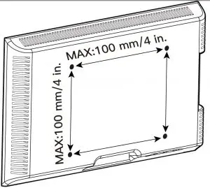
- 75 mm ≈ 3 in.
- 100 mm ≈ 4 in
If your Monitor VESA is greater than 100×100 mm/4×4 in. or less than VESA 75x75mm/3x3in., this mount is NOT compatible.
If this desk mount is NOT compatible, please contact customer service at [email protected] to find a compatible product.
Product Features
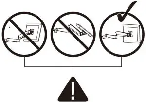
TENSION ADJUSTMENT SHOULD BE DONE ONLY AFTER MOUNT INSTALLATION
![]() Warning Icon: Do not adjust tension without monitor
Warning Icon: Do not adjust tension without monitor
- Ensure monitor has been attached to the mount.
- Read your monitor box or manual to find out monitor net weight.
- Ensure the net weight of monitor (including accessories) is between 4.4~26.5 Ibs (2-12 kg) per arm.
Adjustment Sign
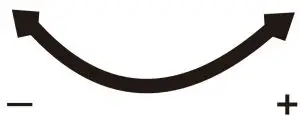
- Clockwise to reduce tension(carry less weight)
- Counter-clockwise to increase tension(carry more weight)
![]() Warning
Warning

Tools Needed (Not lncluded)
Screwdriver
Supplied Parts and Hardware
![]() Warning: This product contains small items that could be a choking hazard if swallowed.Before starting assembly, verify all parts are included and undamaged. Do not use damaged or defective parts. lf you require replacement parts, contact our customer service at [email protected].
Warning: This product contains small items that could be a choking hazard if swallowed.Before starting assembly, verify all parts are included and undamaged. Do not use damaged or defective parts. lf you require replacement parts, contact our customer service at [email protected].
- Please note: Not all hardware included in this package will be used.
Supplied Parts and Hardware for Step 1
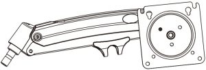
- C-Clamp X1

- Pole Assembly X1
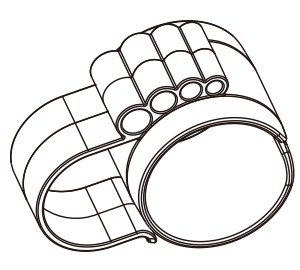
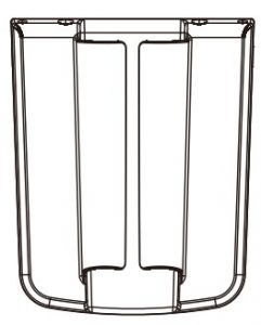
- Cable Clip X2
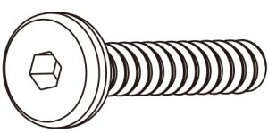
- Bolt (C) M6x12mm (4pcs)
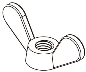
- (D) Butterfly Nut x1
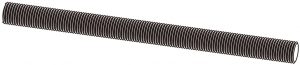
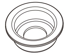
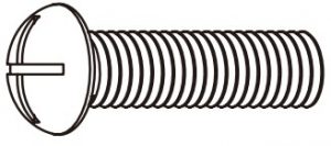
- (D) Grommet Bolt x1
- (E) Locking Plate x1
- (F) x1 5/32 in.(4mm) Allen Key


Supplied Parts and Hardware for Step 3
- Arm X2
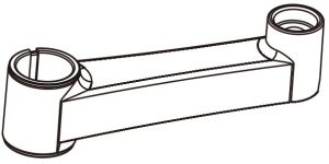
- Extension Arm x2
- Locating Ring X2
- (G) Plastic Sleeve X2
- (F) x1 1/8 in.(3mm) Allen Key
- (F) x1 5/32 in.(4mm) Allen Key

Supplied Parts and Hardware for Step 3
- Bolt (A) M4x12mm (X8)
- Bolt (B-1) M4x16mm (X8)
- Spacer (B-2) 5mm (X8)


Supplied Hardware for Step 4 and Step 6
- (F) 13/64 in.(5mm) Allen Key
Supplied Part for Step 8
- Cable Cover x1
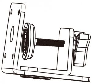
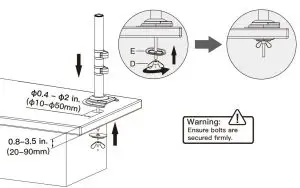
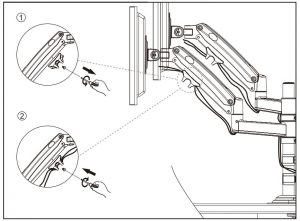
Install the Base
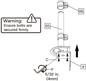
A. For Clamp Mounting
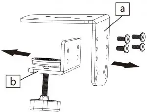
- Detach the c-clamp entirely
- Slide the cable clips [06] to pole assembly [05] and secure part [a] to pole assembly [05]Warning: Ensure bolts are secured firmly.
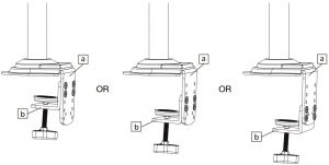
- Connect part [b] to part [a] according to the thickness of the desktop.
- Secure the pole assembly to the desktop
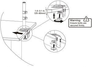
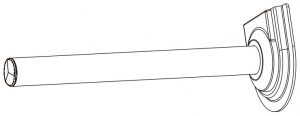
B. For Grommet Mounting
- Install the grommet bolt [D] to the bottom of pole assembly [05]Warning: Ensure bolts are secured firmly.
- Secure the pole assembly to the desktop with grommet
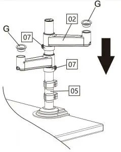
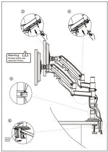
Install the Arms
- Fasten the locating ring [07] at your desired height.
- Slide the extension arms [02] to the pole assembly [05], and attach the plastic sleeves [G] to extension arms [02]Warning: Ensure bolts are secured firmly.
- Attach the arms [01] to the extension arms [02
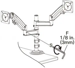
- Secure the arms [01] to the extension arms [02] by tightening the preassembled set screw [S] using Allen key [F]Warning: Ensure bolts are secured firmly.

 Warning: Ensure bolts are secured firmly.
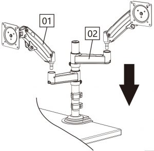
 Warning: Ensure bolts are secured firmly.
Step 3 Attach Monitors to the Arms
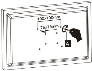
3-1 Choose Proper bolts
Flat back monitor
Round back monitor
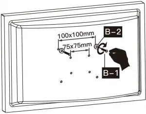
For VESA hole pattern:
- 3 in. (75mm) x 3 in. (75mm)
- 4 in. (100mm) x 4 in. (100mm
3-2 Install Monitors to the Arms
![]() Screw Driver [Not Included]
Screw Driver [Not Included]
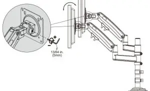
- 0.1-0.2in.(3-5mm) spacing leftThe tension is preset at 8.8~11 Ibs(4-5kg). After hanging the monitor to the mount, please release the monitor slowly to prevent it from falling suddenly.Warning: Ensure bolts are secured firmly.
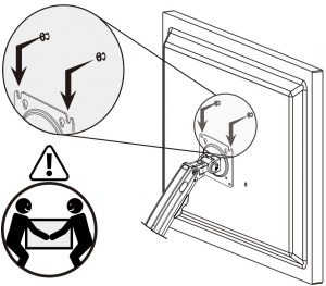 The tension is preset at 8.8~11 Ibs(4-5kg). After hanging the monitor to the mount, please release the monitor slowly to prevent it from falling suddenly.
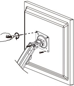 Warning: Ensure bolts are secured firmly.
Adjust Gas Spring Tension
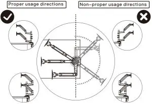
Be sure to keep the arm in horizontal position during adjustment. Or else, it would be difficult to adjust the mount or damage the mount.
- If the monitor can stay at the desired height by itself, no adjustment needed.
- If the monitor rises up, press the arm to keep it in horizontal position and then use the 13/64 in.(5mm) Alley key (F) to turn the bolt clockwise(“-” direction) to reduce tension of the arm only until the monitor can stay at the desired height by itself.
- If the monitor falls down, lift the arm to keep it in horizontal position and then use the 13/64 in.(5mm) Alley key (F) to turn the bolt counter-clockwise (“+” direction) to increase tension of the arm only until the monitor can stay at the desired height by itself.

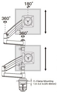
Rotation Restriction
Tilt Adjustment
“+” Clockwise: Tighten“-” Counter-clockwise: LoosenSituation 1: If the monitor can stay at the desired tilt angle by itself, no adjustment needed.Situation 2: If the monitor can not stay at the desired tilt angle by itself, turn the bolt clockwise or counter-clockwise as shown until the monitor can stay at the desired tilt angle by itself.
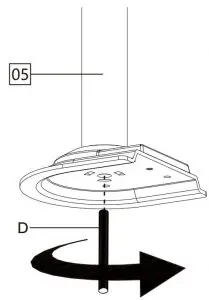
Rotation Adjustment
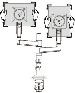 360 Rotation
Only suitable for the monitors with the center of gravity in the center position
Route Cables along the Arms
Warning: Ensure bolts are secured firmly.
Thank you again for choosing this Ergear product!
All of us at Ergear do appreciate your product purchase. We hope that you are as happy with your product as we are designing and manufacturing it for you. We strive to provide you with the best quality products and services in the industry. Should you have any issues, please don’t hesitate to contact us at [email protected] (US/CA/DE/UK/FR/IT/ES/AU)
[xyz-ips snippet=”download-snippet”]