erica FUSION Analog Filter Combined Vacuum Tubes Vactrols User Manual
THANK YOU FOR ORDERING ERICA FUSION VCF3!
The Erica Synths Fusion series modules are designed combining vacuum tubes and semiconductors therefore they bring warm, powerful sound and overdrive possibilities of vacuum tubes into your modular system. Erica Fusion series consist of range of modules used in sound generation and shaping circuit – two types of VCO, Mixer, real Ring modulator using audio transformers and germanium diode ring, two VCFs, VCA, Analogue Delay/Flanger, Palsma Drive and others. Also Erica Fusion Systems are available.
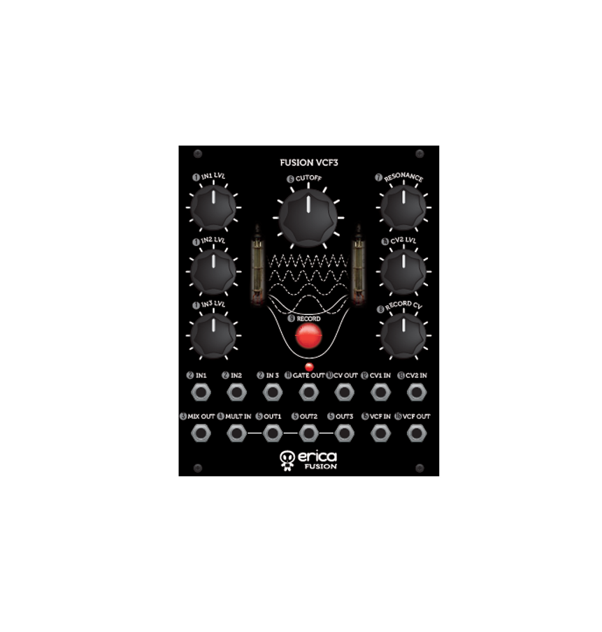
The Fusion VCF3 is resonant 24dB/oct lowpass filter of unique design that combines vacuum tubes and vactrols, providing distinct, soft filtering. For more versatility, the independentaudio mixer and buffered multiple is incorporated in the module, and, most importantly – a CV recorder that records motion of the potentiometer, so you candesign advanced modulation patterns.
- These are audio mixer input level controls. The mixer has gain 2, so you can overdrive the signal for nice distortion effects.
- These are the audio mixer inputs.
- This is dedicated mixer output. If nothing is patched here, it is normalled to the VCF input.
- This is precision buffered multiple input. Use it to split audio and CV signals for use in several modules, also for feedback loops.
- These are buffered multiple outputs.
- This is manual VCF cutoff frequency control knob; the CV is added to the knob position.
- This is the VCF resonance control
- This is CV record knob. Rotate it to record a desired automation. When the automation is played back, the knob becomes divider and multiplier. If you rotate the knob past 12:00 clockwise, multiplication with 2, 3, 4, 8 is available, when rotating it counterclockwise, same divisions are available.
- This is CV record button. In order to record the potentiometer automation, push and hold the button and rotate the potentiometer. The brightness of the knob willindicate the CV output. To record a next automation, push and hold the CV record button while the previous automation is playing and rotate the CV record potentiometer;the previous automation will be deleted. You can pause the automation playback on the momentary CV value by pushing the CV record knob promptly once. To clear the recorded buffer, push the button twice.
- This is the recorded CV Output. Maximum CV range is 0 – +5V. The CV Output is normalled to the VCF CV IN1, so, if nothing is patched into CV1 IN, the recordedCV directly controls the VCF cutoff. Obviously, you can use the recorded CV to control other modules in your system.
- This is the gate output – the unit will output +5V gate, when the RECORD CV knob is turned past 12:00; the LED gives visual feedback on the gate ON. You canuse gate out for creating rhythmic patterns manually.
- This is the first external cutoff CV input, and it’s normalled to the CV recorder output. So, if nothing is patched here, the CV OUT of the recorder controls VCF cutoff.
- This is the second cutoff CV input.
- This is an external cutoff CV2 attenuator. CV1 and CV2 are mixed, so you can adjust CV levels for best effect.
- This is the VCF audio input. It is normalled to the Mixer output, so you can mix several audio sources before the VCF. If you use the mixer output for patching mixeroutput to different modules, patch the VCF audio input here.
- This is the VCF output
FEATURES:
Full analogue design Vacuum tube and vactrol based filter circuit. Because of vactrol lag, the VCF will not accept audio rate modulation, the maximummodulation frequency is 10Hz Input signal mixer with gain 2 for signal overdriveBuffered multiple for splitting audio and CV signalsPotentiometer motion record unit with CV and gate outputsRecorded CV multiplication and division
TECHNICAL SPECIFICATIONS:
Filter slope 24dB/octAudio Input level 10VptpCV input level -5V – +5VCV Output level 0V – +5VPanel width 20HPModule depth 36mmPower consumption +12V,
SAFETY INSTRUCTIONS
Please follow the instructions for use of the Erica Synths module below, ‘cause only this will guarantee proper operation of the module and ensure warranty from Erica Synths
 Water is lethal for most of the electric devices, unless they are made waterproof. This Erica Synths module is NOT intended for use in a humid or wet environment. Noliquids or other conducting substances must get into the module. Should this happen, the module should be disconnected from mains power immediately, dried, examined and cleaned by a qualified technician.
 Do not expose the module to temperatures above +50° C or below -20° C. If you have transported module in extreme low temperatures, leave it in room temperature for anhour before plugging it in.
 Transport the instrument carefully, never let it drop or fall over. Warranty does not apply to modules with visual damages.
 The module has to be shipped in the original packaging only. Any module shipped to us for return, exchange and/or warranty repair has to be in its original packaging. All other deliveries will be rejected and returned to you. Make sure you keep the original packaging and technical documentation.
 This device complies to the EU guidelines and is manufactured RoHS conforming without use of lead, mercury, cadmium and chrome. Nevertheless, this device isspecial waste and disposal in household waste is not recommended.
User manual by Girts Synths.Design by Ineta Copying, distribution or any commercial use in any way is prohibited and needs the written permission by Erica Synths.Specifications are subject to change without notice.In case of any questions, feel free to contact us through www.ericasynths.lv.
You will find Erica Synths terms of warranty at www.ericasynths.lvItems for return, exchange and/or warranty repair have to be sent to:Erica Synths Andrejostas Str. 43RigaLatviaLV-1045
Read More About This Manual & Download PDF:
References
[xyz-ips snippet=”download-snippet”]