etiampro Pir Sensor With Double Twin Optics User Manual
USER MANUAL
1. Introduction
![]() To all residents of the European Union Important environmental information about this product This symbol on the device or the package indicates that disposal of the device after its lifecycle could harm the environment. Do not dispose of the unit (or batteries) as unsorted municipal waste; it should be taken to a specialized company for recycling. This device should be returned to your distributor or to a local recycling service. Respect the local environmental rules. If in doubt, contact your local waste disposal authorities.
To all residents of the European Union Important environmental information about this product This symbol on the device or the package indicates that disposal of the device after its lifecycle could harm the environment. Do not dispose of the unit (or batteries) as unsorted municipal waste; it should be taken to a specialized company for recycling. This device should be returned to your distributor or to a local recycling service. Respect the local environmental rules. If in doubt, contact your local waste disposal authorities.
Thank you for choosing EtiamPro! Please read the manual thoroughly before bringing this device into service. If the device was damaged in transit, do not install or use it and contact your dealer.
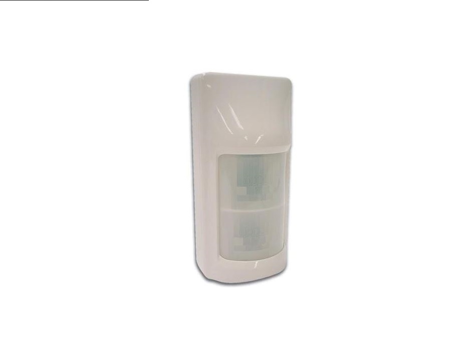
The HAA54 employs “Double-Twin Optics”-technology and the security logic is supplied by the ASIC-processor (Application Specific Integrated Circuit), which was developed for this specific application.The Double-Twin Optics system combines two optical structures and heat detectors in one housing. Both heat detectors are equipped with a dual-element that produces low-level noise only. This enables the HAA54 to create a detection pattern that only reacts to actual intruders and ignores pets or rodents. The Double-Twin Optics system is controlled by the ASICprocessor. This processor detects the change in polarity of a signal caused by an intruder. Thanks to this technique, both channels have a high degree of immunity against common radio interference and power surges. This processor also provides the HAA54 with a number of additional functions: digital pulse counting, temperature compensation, warm-up delay, alarm controls, and an alarm activation delay. These characteristics maximize security and provide excellent protection against false alarms.
2. Safety Instructions
![]() Read and understand this manual and all safety signs before using this appliance.
Read and understand this manual and all safety signs before using this appliance.
- This device can be used by children aged from 8 years and above, and persons with reduced physical, sensory or mental capabilities or lack of experience and knowledge if they have been given supervision or instruction concerning the use of the device in a safe way and understand the hazards involved. Children shall not play with the device. Cleaning and user maintenance shall not be made by children without supervision.
3. General Guidelines
- Refer to the Velleman® Service and Quality Warranty on the last pages of this manual.
- All modifications of the device are forbidden for safety reasons. Damage caused by user modifications to the device is not covered by the warranty.
- Only use the device for its intended purpose. Using the device in an unauthorized way will void the warranty.
- Damage caused by disregard of certain guidelines in this manual is not covered by the warranty and the dealer will not accept responsibility for any ensuing defects or problems.
- Nor Velleman NV nor its dealers can be held responsible for any damage (extraordinary, incidental, or indirect) of any nature (financial, physical…) arising from the possession, use, or failure of this product.
- Keep this manual for future reference.
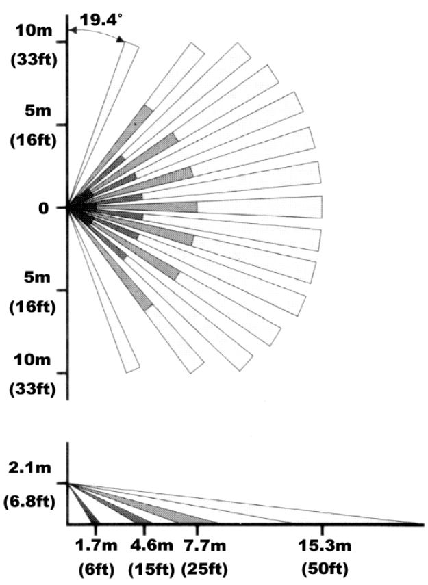
4. Detection Pattern
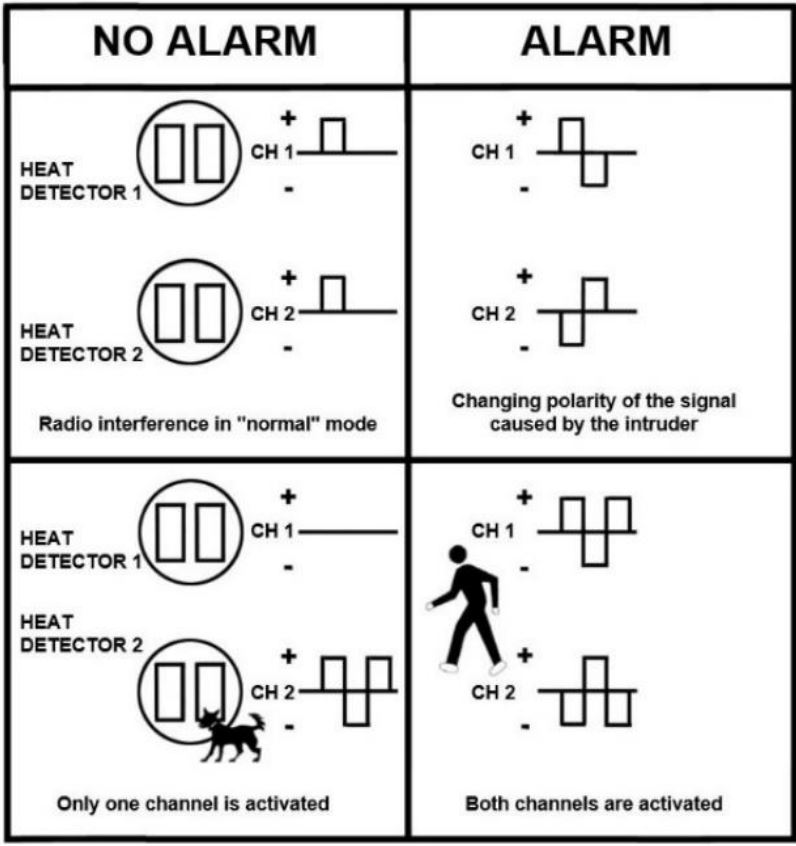
5. Double-Twin Optics System
Detection of changing polarity.
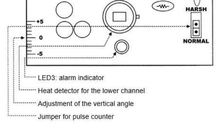
6. PCB Layout
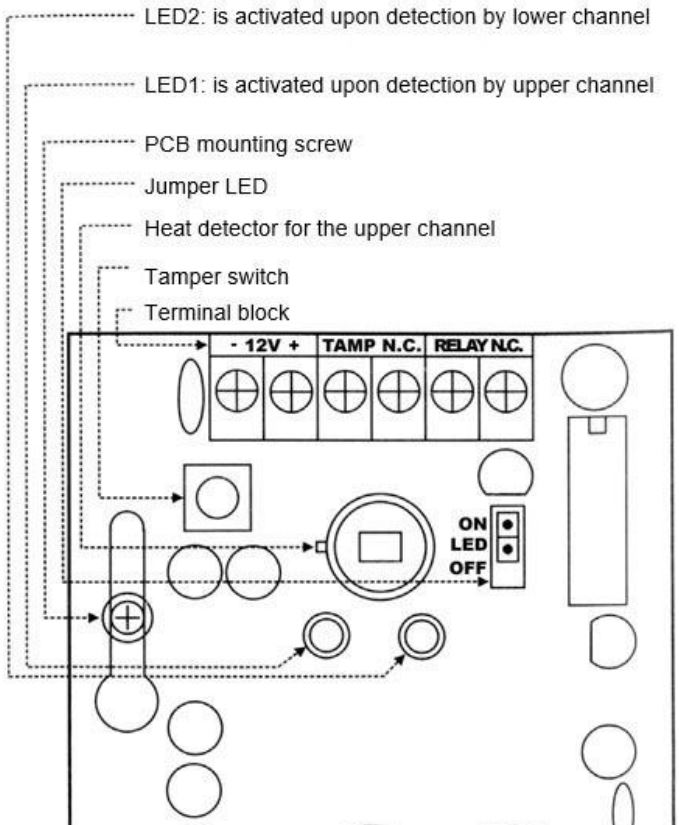
Terminal Block
12VConnect the positive terminal (+) to a power source of 9-16VDC on the alarm control panel. Connect the negative terminal (-) to the grounding point of the control panel.
TAMPER NCConnect these terminals to a 24hr N.C. (Normally Closed) protection zone of the alarm control panel. The tamper switch contact is closed if the detector’s front cover is in place. The contact will open and an alarm signal will instantly be sent to the control panel if the front
RELAY NCthe cover is removed at any time. This is the alarm output relay of the detector. These two terminals should be connected to an N.C. protection zone of the alarm control panel.
Jumper Settings
LEDPlace the jumper in the “ON”-position to arm all LEDs or place it in the “OFF”-position to deactivate all LEDs. Detection is still possible
PULSEwith the jumper in the “OFF”-position. Place the pulse count jumper in the “NORMAL” position for standard detection in a stable environment. Place the pulse count jumper in the “HARSH”-position for double detection within 12 seconds. Pets are ignored in this mode, which is particularly useful if the device is installed in an unstable environment.
LED Indicators
LED 1 “ON” upon detection by the upper channelLED 2 “ON” upon detection by the lower channelLED 3 “ON” when the alarm is activated, flashes during the warm-up delay
Adjustment of the Vertical AngleLoosen the fixing screw of the PCB in order to move the PCB up or down. This enables the user to adjust both the detection angle and the reach of the device while avoiding the detection of small (domestic) animals.
Heat DetectorsThis device is equipped with two heat detectors for motion detection. DO NOT TOUCH THE HEAT DETECTORS!
7. Installation
Mounting Location
- The detector can be mounted on a flat surface (e.g. a wall) or in a corner. Select a stable surface.
- This detector should only be used indoors and should be installed in an environment that is shielded from the elements.
- Do not expose the device to cold or warm air currents.
- Do not aim the detector at heating devices, air conditioning vents, windows, refrigerator or freezer grilles, or any other surface that is subject to violent and sudden changes in temperature.
- Do not place large objects in front of the detector, as this will significantly diminish the area protected by the detector’s beams.
- Select a mounting location that allows you to place the detector at an angle of 45° (= optimal) with reference to the intruder’s expected path. The detector should preferably be mounted in a corner.
- Installation height: 2 to 3 m (7 to 10 ft).
Removing the Front Cover
- Loosen the screw.
- Insert the tip of a screwdriver into the latching slot and release the front cover.
- Remove the front cover.
Removing the PCBThe PCB should be removed before mounting the back cover.
- Loosen the fixing screw of the PCB.
- Push the PCB upward until the head of the screw will pass through the opening.
- Remove the PCB carefully.
Mounting the Back CoverThe back cover is suited for wall or corner mounting.
- Feed the power cord through the push-out hole at the top and on the inside of the back cover.
- The push-out holes at the back are suitable for surface or wall mounting. The ones at the sides are suitable for corner mounting.
- Mount the back cover.
Mounting the Front Cover, Wiring
- Reinsert the PCB and use the fixing screw to fix the PCB firmly.
- Connect the wires to the terminal block.
- Replace the front cover and make sure the tamper switch is depressed when the front cover is clicked into place. Close the housing firmly with the fixing screw.
The Walk Test
- The walk test can be performed as soon as the warm-up delay is finished, in other words when the alarm LED stops flashing. The walk test is necessary in order to verify whether the device is in good working order and whether it covers the desired area.
- The alarm will sound when both the upper and lower channels are triggered simultaneously when the jumper is in the “NORMAL” position.
- If the jumper is in the “HARSH” position, the alarm will sound upon simultaneous and double activation of both channels in a space of 12 seconds.
- The detection range and the vertical angle of the device can be adjusted by sliding the PCB up or down.
8. Technical Specifications
current consumption ……………………… 15 mA typical at 12 VDCoperating voltage………………………..9-16 VDC, 12 VDC nominaldetection method…………… PIR detection with changing polarity,………………………………………….”Double Twin Optics” systemwarm-up delay ………. 2 min. typical, with flashing, LED indicationalarm activation delay ……………………………………………..2-3 salarm output …….N.C. relay contact with a 10 resistor in series…………………………………………. contact rating: 28 VDC, 0.1 Awalk-test LEDs …………… upper/lower channels, alarm indicators……………………………………… can be armed or disarmed at willpulse counter ………………………….. normal response or 2 pulses………………………………………. within 12 s in “HARSH”-positiontamper switch ………… N.C. contact with a 10 resistor in series…………………………………………contact rating: 12 VDC, 50 mAoperating temperature ………………………………… -10 to +55 °Chumidity ………………………………………… 95 % non-condensingEMC …………………………………… conform to CE-label standardsdimensions ………………………….. 64 (W) x 45 (H) x 127 (L) mm
Use this device with original accessories only. Velleman NV cannot be held responsible in the event of damage or injury resulting from (incorrect) use of this device. For more info concerning this product and the latest version of this manual, please visit our website www.Velleman.EU. The information in this manual is subject to change without prior notice.
© COPYRIGHT NOTICE The copyright to this manual is owned by Velleman NV. All worldwide rights reserved. No part of this manual may be copied, reproduced, translated or reduced to any electronic medium or otherwise without the prior written consent of the copyright holder.
Velleman® Service and Quality WarrantySince its foundation in 1972, Velleman® acquired extensive experience in the electronics world and currently distributes its products in over 85 countries.All our products fulfill strict quality requirements and legal stipulations in the EU. In order to ensure the quality, our products regularly go through an extra quality check, both by an internal quality department and by specialized external organizations. If, all precautionary measures notwithstanding, problems should occur, please make an appeal to our warranty (see guarantee conditions).General Warranty Conditions Concerning Consumer Products (for EU):
- All consumer products are subject to a 24-month warranty on production flaws and defective material as from the original date of purchase.
- Velleman® can decide to replace an article with an equivalent article or to refund the retail value totally or partially when the complaint is valid and a free repair or replacement of the article is impossible, or if the expenses are out of proportion. You will be delivered a replacing article or a refund at the value of 100% of the purchase price in case of a flaw that occurred in the first year after the date of purchase and delivery, or a replacing article at 50% of the purchase price or a refund at the value of 50% of the retail value in case of a flaw occurred in the second year after the date of purchase and delivery.
- Not covered by warranty:– all direct or indirect damage caused after delivery to the article (e.g. by oxidation, shocks, falls, dust, dirt, humidity…), and by the article, as well as its contents (e.g. data loss), compensation for loss of profits;– consumable goods, parts, or accessories that are subject to an aging process during normal use, such as batteries (rechargeable, non-rechargeable, built-in or replaceable), lamps, rubber parts, drive belts… (unlimited list);– flaws resulting from fire, water damage, lightning, accident, natural disaster, etc….;– flaws caused deliberately, negligently, or resulting from improper handling, negligent maintenance, abusive use or use contrary to the manufacturer’s instructions;– damage caused by a commercial, professional or collective use of the article (the warranty validity will be reduced to six (6) months when the article is used professionally);– damage resulting from an inappropriate packing and shipping of the article;– all damage caused by modification, repair, or alteration performed by a third party without written permission by Velleman®.
- Articles to be repaired must be delivered to your Velleman® dealer, solidly packed (preferably in the original packaging), and be completed with the original receipt of purchase and a clear flaw description.
- Hint: In order to save on cost and time, please re-read the manual and check if the flaw is caused by obvious causes prior to presenting the article for repair. Note that returning a non-defective article can also involve handling costs.
- Repairs occurring after warranty expiration are subject to shipping costs.
- The above conditions are without prejudice to all commercial warranties.
The above enumeration is subject to modification according to the article (see article’s manual).
Made in PRCImported for EtiamPro by Velleman nvLegen Heirweg 33, 9890 Gavere, Belgiumwww.velleman.eu
References
[xyz-ips snippet=”download-snippet”]