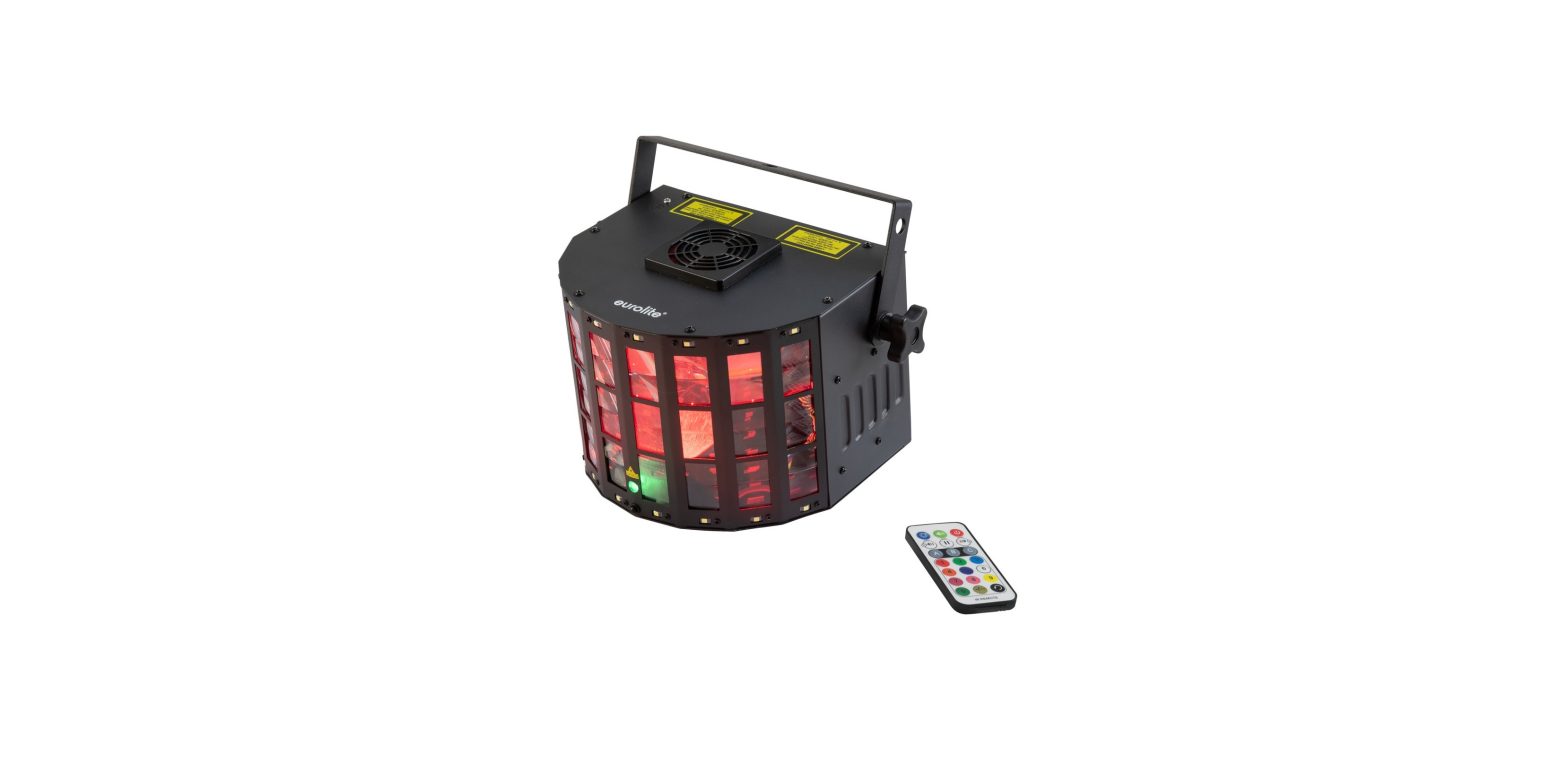
eurolite LED Laser Derby MK2 User Manual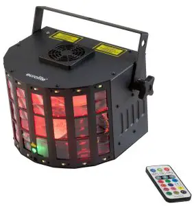
 DANGER! Electric shock caused by short-circuitBe careful with your operations. With a dangerous voltage you can suffer a dangerous electric shock when touching the wires. Never open the housing. Keep the device away from rain and moisture
 Please read these instructions carefully before using the product. They contain important information for the correct use of the product.Every person involved with the installation, operation and maintenance of this device has to
- be qualified
- follow the instructions of this manual
- consider this manual to be part of the total product
- keep this manual for the entire service life of the product
- pass this manual on to every further owner or user of the product
- download the latest version of the user manual from the Interne
INTRODUCTION
Thank you for having chosen one of our products. If you follow the instructions given in this manual, we are sure that you will enjoy this device for a long period of time.
Product features
DMX light effect with RG laser (2M), rotating LED derby, stroboscope and IR remote control
- Four high-power 10 W LEDs in red, green, blue and white for dynamic mirror ball effects
- 16 cold white 0.6 W SMD LEDs for fast, dynamic strobe effects
- 2 laser diodes project thousands of red and green laser beams
- Laser class 2M: does not require additional protective measures or appointment of a laser safety officer
- Auto, music, master/slave and DMX mode
- built-in auto and music show programs
- RGBW color effects, dimmer and strobe effects
- Rotation speed variably adjustable
- Sound-control via built-in microphone with adjustable microphone sensitivity
- DMX512 control possible via any commercial DMX controller
- 2,4,5,6,7,8 or 9 DMX channels selectable for various applications
- Supports QuickDMX – the wireless DMX system from Eurolite
- Built-in phantom-powered USB port for QuickDMX receivers (accessory)
- Addressing and setting via control panel with 4-digit LED display
- Convenient wireless control via included IR remote control EUROLITE IR-16
- Feed-through output allows to power up to 8 devices
SAFETY INSTRUCTIONS
![]() WARNING!Please read the safety warnings carefully and only use the product as describe in this manual to avoid accidental injury or damage.
WARNING!Please read the safety warnings carefully and only use the product as describe in this manual to avoid accidental injury or damage.
Intended use
- This device is an LED laser projector for creating decorative lighting effects. This device is designed for professional use in the field of event technology, e.g. on stage. It is not suitable for household lighting.
- Only use the device according to the instructions given herein. Damages due to failure to follow these operating instructions will void the warranty! We do not assume any liability for any resulting damage.
- We do not assume any liability for material and personal damage caused by improper use or noncompliance with the safety instructions. In such cases, the warranty/guarantee will be null and void.
- Unauthorized rebuilds or modifications of the device are not permitted for reasons of safety and render the warranty invalid.
Danger due to electricity
- The device is suitable for indoor use only. Do not use it outdoors. Never expose it to rain or moisture. Do not store it in rooms exposed to moisture.
- To reduce the risk of electric shock, do not open any part of the device. There are no serviceable parts inside the device.
- Only connect the device to a properly installed mains outlet. The outlet must be protected by residual current breaker (RCD). The voltage and frequency must exactly be the same as stated on the device. If the mains cable is equipped with an earthing contact, then it must be connected to an outlet with a protective ground. Never defeat the protective ground of a mains cable. Failure to do so could result in damage to the device and possibly injure the user.
- The mains outlet must be easily accessible so that you can unplug the device quickly if need be.
- Never touch the mains plug with wet or damp hands. There is the risk of potentially fatal electric shock.
- The mains cable must not be bent or squeezed. Keep it away from hot surfaces or sharp edges.
- Never pull the mains cable to disconnect the mains plug from the mains outlet, always seize the plug.
- Unplug the device during lighting storms, when unused for long periods of time or before cleaning.
- Do not expose the device to any high temperatures, direct sunlight, dripping or splashing water, strong vibrations or heavy mechanical stress.
- Do not place any objects filled with liquids on the device.
- Do not place any open sources of fire, such as burning candles, on or directly next to the device.
- Make sure that objects cannot fall into the device, in particular metal parts.
- Only have repairs to the device or its mains cable carried out by qualified service personnel. Repairs are required when the device or the mains cable is visibly damaged, liquid has been spilled or objects have fallen into the device; when the device has been exposed to rain or moisture, has been dropped or malfunctions occur.
- Cleaning of the device is limited to the surface. Make sure that moisture does not come into contact with any areas of the terminal connections or mains voltage control parts. Only wipe off the product with a soft lint-free and moistened cloth. Never use solvents or aggressive detergents.
Danger to children and people with restricted abilities
- This product is not a toy. Keep it out of the reach of children and pets. Do not leave packaging material lying around carelessly. Never leave this device running unattended.
- This device may be used only by persons with sufficient physical, sensorial, and intellectual abilities and having corresponding knowledge and experience. Other persons may use this device only if they are supervised or instructed by a person who is responsible for their safety.
Warning – risk of burns and fire
- The admissible ambient temperature range (Ta) is -5 to +45°C. Do not operate the device outside of this temperature range.
- The housing temperature (Tc) can be up to 65°C during use. Avoid contact by persons and materials.
- Do not illuminate surfaces within 1.0 m of the device. This value is indicated on the device by the symbol.
- Do not use the device near highly flammable materials. Always place the device at a location where sufficient air circulation is ensured. Leave 50 cm of free space around the device. Never cover the air vents of the housing.
Warning – risk of injuries
- Do not look directly at the light source. Persons with light-sensitive epilepsy may suffer from epileptic seizures or fall unconscious.
- Make sure that the product is set up or installed safely and expertly and prevented from falling down. Comply with the standards and rules that apply in your country, in particular EN 60598-2-17.
- If you lack the qualification, do not attempt the installation yourself, but instead use a professional installer. Improper installation can result in bodily injury and or damage to property.
- The manufacturer cannot be made liable for damages caused by incorrect installations or insufficient safetyprecautions.
- For overhead use, always secure the device with a secondary safety attachment such as a safety bond or safety net.
- Make sure that the area below the installation place is blocked when rigging, derigging or servicing the device.
- For commercial use the country-specific accident prevention regulations of the government safety organization for electrical facilities must be complied with at all times.
Caution – material damage
- This device must not be connected to the mains voltage by means of a dimmer.
- Lighting effects are not designed for permanent operation. Consistent operation breaks will ensure that the device will serve you for a long time without defects.
- Never switch the device on and off at short intervals. This will considerably reduce the service life of the device.
- If the device has been exposed to drastic temperature fluctuation, do not switch it on immediately. The resulting condensation may destroy the device. Allow the device to reach room temperature before connecting it. Wait until the condensation has evaporated.
- Please use the original packaging to protect the device against vibration, dust and moisture during transportation or storage.
- If a serial number label is affixed to the device, do not remove the label as this would make the guarantee void.
About batteries
- Do not try to short-circuit, recharge, disassemble or heat batteries (danger of explosion!).
- Remove the batteries if the device is not used for a longer period of time.
- Damaged/leaking batteries may cause harm to your skin use safety gloves.
Important information for laser products
![]() DANGER!Avoid direct eye exposure. Never view directly with optical instruments (e.g. magnifying lens or telescope). Laser radiation can cause eye damage and/or skin damage. All protective measures for a safe operation of this laser must be applied.
DANGER!Avoid direct eye exposure. Never view directly with optical instruments (e.g. magnifying lens or telescope). Laser radiation can cause eye damage and/or skin damage. All protective measures for a safe operation of this laser must be applied.
Safety measures which must be observed
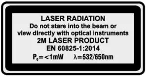
- This device includes a class 2M laser according to the EN 60825-1. The accessible laser radiation is exclusively within the visible spectral range (400 nm to 700 nm). However, a short-term exposure (max. 0.25 seconds) is not hazardous to the eye. A longer exposure is prevented by the natural eyelid closing reflex. Nevertheless, close your eyes or turn away immediately if the laser beam hits the eye. The corresponding warning is attached to the housing.
- The operator must comply with the country-specific accident prevention regulations of the government safety organization for electrical facilities.
- The corresponding accident prevention regulation of the accident prevention and insurance association in Germany is BGV-B2.
- This product must only be mounted, commissioned and operated by suitably qualified specialist personnel and only under observance of the requirements stated in the operating instructions.
- The use of operating and adjustment equipment and procedures other than those indicated here can lead to dangerous exposure to radiation.
- Do not stare into the laser beam and do not aim the laser at another person or animals. Laser radiation may result in injuries to the eyes or skin.
- Do not look into the laser beam with optical instruments (e.g. magnifying glasses or binoculars) under any circumstances. Laser radiation can cause eye damage and/or skin damage.
- Do not point the laser beam at mirrors or other reflective surfaces. The uncontrolled, reflected beam may strike people or animals.
- Always set up and install the unit so that a minimum distance of 1 m is kept between the laser light and the audience.
- Mark the area where this laser equipment is used by means of barriers and warning signs etc.
- Caution laser diode! Do not open or modify the unit. A modification can result in a more hazardous laser radiation which considerably deviates from the specified values.
DESCRIPTION OF THE DEVICE
Front
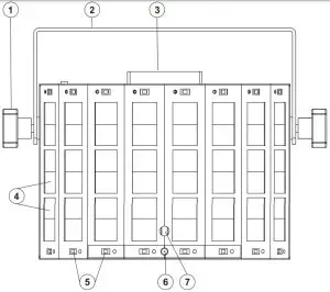
- Fixation screw
- Mounting bracket
- Fan
- RGBW LEDs
- SMD LEDs
- Laser output aperture
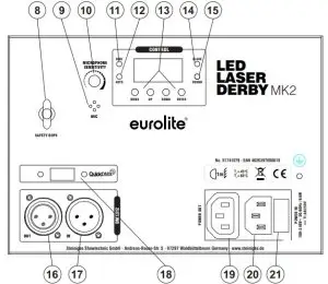
- Infrared sensor for the remote controlRear

- Safety eyelet
- Microphone
- Rotary control for sensitivity
- Indicator for DMX mode
- Indicator for automatic mode
- Display with operating buttons
- Indicator for slave mode
- Indicator for sound control mode
- DMX output
- DMX input
- QuickDMX USB port
- Power feed-through output
- Power input
- Fuse holder
INSTALLATION
![]() WARNING! Risk of injury caused by falling objects Devices in overhead installations may cause severe injuries when crashing down. Make sure that the device is installed securely and cannot fall down. The installation must be carried out by a specialist who is familiar with the hazards and the relevant regulations.
WARNING! Risk of injury caused by falling objects Devices in overhead installations may cause severe injuries when crashing down. Make sure that the device is installed securely and cannot fall down. The installation must be carried out by a specialist who is familiar with the hazards and the relevant regulations.
![]() DANGER! Damage caused by laser radiation Observe the chapter safety instructions when installing the device.
DANGER! Damage caused by laser radiation Observe the chapter safety instructions when installing the device.
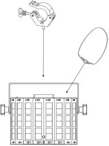
The device may be placed on the floor or fastened to a truss or similar rigging structure. The device must never be fixed swinging freely in the room.
- The rigging structure must support at least 10 times the weight of all fixtures to be installed on it.
- Block access below the work area and work from a stable platform when installing the device.
- Use rigging hardware that is compatible with the structure and capable of bearing the weight of the device. Please refer to the “Accessories” section for a list of suitable rigging hardware.
- Secure the device with a safety bond or other secondary attachment. This secondary safety attachment must be sufficiently dimensioned in accordance with the latest industrial safety regulations and constructed in a way that no part of the installation can fall down if the main attachment fails. An appropriate eyelet is mounted on the device for fixation of the safety bond. Fasten the safety bond in such a way that, in the event of a fall, the maximum drop distance of the device will not exceed 20 cm.
- To align the device, release the fixation screws at the mounting bracket, adjust the desired inclination angle and tighten the fixation screws.
- After installation, the device requires inspections periodically to prevent the possibility of corrosion, deformation and looseness.
CONNECTIONS
DMX512 controlA DMX512 data link is required in order to control the device via DMX. The device provides 3-pin XLR connectors for DMX connection.Connect the output of your DMX controller to the DMX input DMX IN of the light set with a DMX cable.Connect the DMX output DMX OUT of the light set to the DMX input of the next unit in the chain. Always connect one output to the input of the next unit until all units are connected.At the last unit, the DMX cable has to be terminated. Plug the terminator with a 120 Ω resistor between Signal (–) and Signal (+) in the DMX output of the last unit.If the cable length exceeds 300 m or the number of DMX devices is greater than 32, it is recommended to insert a DMX level amplifier to ensure proper data transmission.
XLR connection
DMX-Output: XLR Mountiing-socket
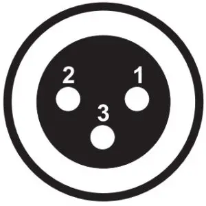
- Ground
- Signal (-)
- Signal (+)
DMX-input: XLR Mountiing-plug
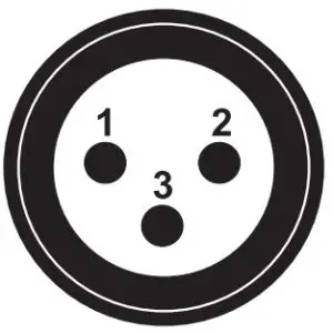
- Ground
- Signal (-)
- Signal (+)
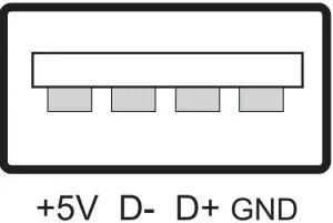
Wireless DMX transmission with QuickDMXThe device features an alternative DMX input for a QuickDMX receiver (sold separately). This connector allows for wireless transmission of DMX control signals to the device. The connector is designed as a USB port which provides the required 5 V operating voltage for the receiver. With QuickDMX devices, extensive cabling between the DMX controller and the device is not required.Occupation of the USB port:
Connection to the mainsThe device uses an auto-range power supply that accepts input voltages between 100 und 240 volts.
- Connect the device via the mains cable to a grounded mains socket. Thus the unit is switched on.
- To switch off the unit, disconnect the power plug.
- Do not connect the unit to the mains voltage via a dimmer. For a more convenient operation, use a mains outlet which is switchable.
Power supply of further devicesThe jack POWER OUT allows for power supply of further devices. To interconnect several devices, connect the jack POWER OUT to the input POWER IN of the next unit until all units are connected. Matching power cables with IEC plugs are available as accessories. In this manner, up to 8 devices can be linked at 230/240 input voltage and up to 4 devices at 110/115 input voltag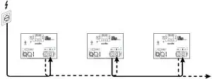
OPERATION
After connecting the device to the mains it is ready for operation. The display indicates the last operating mode. The operating modes can be selected by means of the display and the control buttons. All settings remain stored even if the device is disconnected from the mains. The device can be operated in stand-alone mode via the control board and the EUROLITE IR-16 remote control or in DMX-controlled mode via any commercial DMX controller.Microphone sensitivity in Stand Alone mode can be adjusted via the rotary dial.
Operating buttons
MENU: Selects the operating mode or returns to the initial screenENTER: Activates a value to be modified or saves a value when modifyingUP: Selects the next menu item or increases values when modifyingDOWN: Selects the previous menu item or decreases values when modifying
Menu structure
|
Display |
Function |
|||
|
AUT |
Auto programs (Master mode) | |||
| Aut1 | Derby + Strobe + Laser | |||
| Aut2 | Derby + Strobe | |||
| Aut3 | Derby + Laser | |||
| Aut4 | Strobe + Laser | |||
| Aut5 | Derby | |||
| Aut6 | Strobe | |||
| Aut7 | Laser | |||
| S.01-S.99 | Speed (increasing) | |||
|
SOU |
Sound controlled programs (Master mode) |
|||
| Sou1 | Derby + Strobe + Laser | |||
| Sou2 | Derby + Strobe | |||
| Sou3 | Derby + Laser | |||
| Sou4 | Strobe + Laser | |||
| Sou5 | Derby | |||
| Sou6 | Strobe | |||
| Sou7 | Laser | |||
|
COL |
COLO |
rXXX | r000 ~ 255 | Intensity setting of the red LED (0 – 100%) |
| GXXX | G000 ~ G255 | Intensity setting of the green LED (0 – 100%) | ||
| BXXX | B000 ~ B255 | Intensity setting of the blue LED (0 – 100%) | ||
| WXXX | W000 ~ W255 | Intensity setting of the white LED (0 – 100%) | ||
| FXXX | F0 ~ F99 | Derby strobe effect, increasing speed | ||
|
DMX |
Setting DMX channel mode DMX address setting |
|||
|
dXXX |
2CH
4CH 5CH 6CH 7CH 8CH 9CH |
d 001-d 511
d 001-d 509 d 001-d 508 d 001-d 507 d 001-d 506 d 001-d 505 d 001-d 504 |
2-Channel DMX Mode
4-Channel DMX Mode 5-Channel DMX Mode 6-Channel DMX Mode 7-Channel DMX Mode 8-Channel DMX Mode 9-Channel DMX Mode |
|
| SLA | Slav | Setting for the Slave device | ||
|
SYS |
LEDS * | ON OFF | Display energy saving mode on Display energy saving mode off | |
| TEST | YES NO | Automatic function check | ||
| REST | YES
NO |
Restore factory default |
* = When ON, the display shows a dot after 30 seconds of inactivity
Interconnecting several devices (master/slave operation)
Several devices may be interconnected (max. 32). Then all slave units can be synchronized and controlledwith the master unit without the need for a DMX controller. The devices must be set to the correspondingoperating modes.
- Configure all slave units before connecting the master unit: Press the MENU button so many times until SLAV is indicated on the display. Confirm with the ENTER button.
- Connect the DMX output of the master unit to the DMX input of the first slave unit. Then connect the DMX output of the first slave unit to the DMX input of the second slave unit, etc. until all units have been connected in a chain. Make sure the master unit is the first in the chain. Do not connect a DMX controller to the DMX input of the master unit.
- Set the master unit to the desired operating mode. The interconnected devices will now operate synchronously.
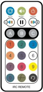
Remote control IR-16The IR remote control allows convenient control of the integrated show programs in automatic mode or sound-controlled mode. Press the buttons repeatedly to switch between the programs. The display indicates the current setting. When actuating a button, always hold the remote control in the direction of the sensor at the control unit’s front or rear. There must be visual connection between the remote control and the sensor.Note: Operation via IR remote control not possible in DMX or slave mode
|
Button |
Function |
 |
On/off |
 |
Auto mode: see graphic for programs 1 – 7* |
 |
Sound control: see graphic for programs 1 – 7* |
 |
Pause |
 |
Derby change of colors |
 |
Derby change of colors |
 |
Derby LED effect |
 |
Strobe effect |
 |
Laser effect |
 |
Program speed adjustment in Auto mode: 0 is lowest, 9 is highest |
 |
Switches between Auto mode and Sound control in A, B or C mode. |
 |
No function |
Note: Buttons A, B and C can be played together if an effect combination is desired
Auto mode and sound-controlled mode always start with program 1.If, for example, no strobe is desired, press the B button to switch off the strobe effect. The menu jumps to program 3 in the display and is played back in that way.Or, if no derby is desired, press the A button to switch off the derby effect. The menu jumps to program 4 in the display and is played back in this way.
| Program 1 | Derby + Strobe + Laser |
| Program 2 | Derby + Strobe |
| Program 3 | Derby + Laser |
| Program 4 | Strobe + Laser |
| Program 5 | Derby |
| Program 6 | Strobe |
| Program 7 | Laser |
Notes:
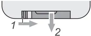
- The remote control is supplied with a battery inserted. An insulating foil between the battery and the battery contacts prevents the battery from being discharged during storage. Prior to the first operation remove the foil from the battery support on the rear side of the remote control. Otherwise operation of the remote control is not possible.
- If the range of the remote control decreases, replace the battery. For this purpose, on the rear side of the remote control press the small bar with the groove to the right and at the same time remove the battery support. For operation, one 3 V button cell type CR 2025 is required. When inserting, pay attention that the positive pole of the button cell shows upwards in the support.
- Remove the battery from the remote control as a precaution if the device is not used for a longer period of time.
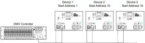
DMX operationSetting the number of DMX channels and the DMX starting addressFor operation with a controller with DMX512 protocol, the device is equipped with max. 9 control channels.However, it can also be switched to a mode with 2, 4, 5, 6, 7 or 8 channels if different functions are required.To be able to operate the device with a DMX controller, the DMX starting address must be set. The startingaddress depends upon which DMX controller is being used. Please refer to the controller’s documentation.
- Press the MENU button so many times until DMX appears on the display. Confirm with the ENTER button. The display next shows dXXX, please confirm again with ENTER.
- The display then indicates 2 CH (2 DMX channels), 4 CH (4 DMX channels), 5 CH (5 DMX channels), 6CH (6 DMX channels), 7 CH (7 DMX channels), 8 CH (8 DMX channels) or 9 CH (9 DMX channels).Use the buttons UP and DOWN to select the desired DMX channel mode. Confirm with the ENTERbutton.
- For the DMX start address press the MENU button until dXXX is shown on the display. Use the buttons UP and DOWN to set the address. Confirm with the ENTER button.
- The red LED next to the display will blink when DMX signals are being received. If no control signals are available, the red LED next to the display will not blink.
Note: Please make sure that you do not have any overlapping channels in order to control each device correctly and independently from any other fixture on the DMX chain. If several devices are addressed similarly, they will work synchronically.
Functions in DMX mode
2-Channel-Mode
|
Channel |
Value | Function |
|
1 Auto programs
Sound control- programs |
000 – 009 |
No Function |
|
010 – 044 |
Derby + Strobe + Laser | |
| 045 – 079 |
Derby + Strobe |
|
|
080 – 114 |
Derby + Laser | |
|
115 – 149 |
Strobe + Laser | |
| 150 – 184 |
Derby |
|
|
185 – 219 |
Strobe |
|
| 220 – 255 |
Laser |
|
|
2 Speed / Sound control |
000 – 250 | Increasing speed of the Auto programs |
|
251 – 255 |
Sound control mode |
4-Channel-Mode
|
Channel |
Value |
Function |
|
1 Derby color presets |
000 – 005 |
No Function |
|
006 – 020 |
Red | |
| 021 – 035 |
Green |
|
|
036 – 050 |
Blue | |
| 051 – 065 |
White |
|
| 066 – 080 |
Red/Greed |
|
|
081 – 095 |
Red/Blue | |
|
096 – 110 |
Red/White | |
| 111 – 125 |
Green/Blue |
|
|
126 – 140 |
Green/White | |
| 141 – 155 |
Blue/White |
|
|
156 – 170 |
Red/Green/Blue |
|
| 171 – 185 |
Red/Green/White |
|
|
186 – 200 |
Green/Blue/White | |
|
201 – 215 |
Red/Green/Blue/White | |
| 216 – 230 |
Automatic 4 color chase |
|
| 231 – 255 |
Automatic 14 color preset combination chase |
|
|
2 Derby Motor Rotation |
000 |
No function |
|
001 – 127 |
Indexing |
|
| 128 – 255 |
Increasing speed |
|
|
3 Laser |
000 – 009 |
No function |
|
010 – 049 |
Red | |
| 050 – 089 |
Green |
|
|
090 – 129 |
Red and green | |
| 130 – 169 |
Red on green strobe |
|
|
170 – 209 |
Green on red strobe |
|
| 210 – 255 |
Red and green strobe alternate |
|
|
4 Strobe |
000 – 009 |
No function |
|
010 – 023 |
Strobe program 1 | |
| 024 – 036 |
Strobe program 2 |
|
|
037 – 049 |
Strobe program 3 | |
| 050 – 062 |
Strobe program 4 |
|
|
063 – 075 |
Strobe program 5 | |
| 076 – 088 |
Strobe program 6 |
|
|
089 – 101 |
Strobe program 7 | |
| 102 – 114 |
Strobe program 8 |
|
| 115 – 127 |
Strobe program 9 |
|
|
128 – 140 |
Strobe program 10 | |
|
141 – 153 |
Strobe program 11 | |
| 154 – 166 |
Strobe program 12 |
|
|
167 – 179 |
Strobe program 13 | |
| 180 – 192 |
Strobe program 14 |
|
| 193 – 205 |
Strobe program 15 |
|
|
206 – 218 |
Strobe program 16 | |
|
219 – 231 |
Strobe program 17 | |
| 232 – 244 |
Strobe program 18 |
|
| 245 – 255 |
Sound control strobe |
5-Channel-Mode
|
Channel |
Value |
Function |
|
1 Derby color presets |
000 – 005 |
No Function |
| 006 – 020 |
Red |
|
|
021 – 035 |
Green | |
| 036 – 050 |
Blue |
|
|
051 – 065 |
White | |
| 066 – 080 |
Red/Greed |
|
|
081 – 095 |
Red/Blue | |
| 096 – 110 |
Red/White |
|
|
111 – 125 |
Green/Blue | |
| 126 – 140 |
Green/White |
|
|
141 – 155 |
Blue/White | |
| 156 – 170 |
Red/Green/Blue |
|
|
171 – 185 |
Red/Green/White | |
| 186 – 200 |
Green/Blue/White |
|
| 201 – 215 |
Red/Green/Blue/White |
|
|
216 – 230 |
Automatic 4 color chase | |
| 231 – 255 |
Automatic 14 color preset combination chase |
|
|
2 Derby Motor Rotation |
000 |
No function |
|
001 – 127 |
Indexing |
|
| 128 – 255 |
Increasing speed |
|
|
3 Laser |
000 – 009 |
No function |
|
010 – 049 |
Red |
|
| 050 – 089 |
Green |
|
|
090 – 129 |
Red and green | |
|
130 – 169 |
Red on green strobe |
|
| 170 – 209 |
Green on red strobe |
|
|
210 – 255 |
Red and green strobe alternate |
|
|
4 Strobe |
000 – 009 |
No function |
| 010 – 023 |
Strobe program 1 |
|
|
024 – 036 |
Strobe program 2 | |
| 037 – 049 |
Strobe program 3 |
|
|
050 – 062 |
Strobe program 4 | |
| 063 – 075 |
Strobe program 5 |
|
|
076 – 088 |
Strobe program 6 | |
| 089 – 101 |
Strobe program 7 |
|
|
102 – 114 |
Strobe program 8 | |
| 115 – 127 |
Strobe program 9 |
|
|
128 – 140 |
Strobe program 10 | |
| 141 – 153 |
Strobe program 11 |
|
|
154 – 166 |
Strobe program 12 | |
| 167 – 179 |
Strobe program 13 |
|
|
180 – 192 |
Strobe program 14 | |
| 193 – 205 |
Strobe program 15 |
|
|
206 – 218 |
Strobe program 16 | |
| 219 – 231 |
Strobe program 17 |
|
|
232 – 244 |
Strobe program 18 | |
| 245 – 255 |
Sound control strobe |
|
|
5 Derby Strobe |
000 – 005 |
No function |
| 006 – 255 |
Strobe frequency with increasing speed |
|
6-Channel-Mode
|
Channel |
Value |
Function |
|
1 Derby color presets |
000 – 005 | No Function |
| 006 – 020 | Red | |
| 021 – 035 | Green | |
| 036 – 050 | Blue | |
| 051 – 065 | White | |
| 066 – 080 | Red/Greed | |
| 081 – 095 | Red/Blue | |
| 096 – 110 | Red/White | |
| 111 – 125 | Green/Blue | |
| 126 – 140 | Green/White | |
| 141 – 155 | Blue/White | |
| 156 – 170 | Red/Green/Blue | |
| 171 – 185 | Red/Green/White | |
| 186 – 200 | Green/Blue/White | |
| 201 – 215 | Red/Green/Blue/White | |
| 216 – 230 | Automatic 4 color chase | |
| 231 – 255 | Automatic 14 color preset combination chase | |
|
2 Derby Motor Rotation |
000 | No function |
| 001 – 127 | Indexing | |
| 128 – 255 | Increasing speed | |
|
3 Laser |
000 – 009 | No function |
| 010 – 049 | Red | |
| 050 – 089 | Green | |
| 090 – 129 | Red and green | |
| 130 – 169 | Red on green strobe | |
| 170 – 209 | Green on red strobe | |
| 210 – 255 | Red and green strobe alternate | |
|
4 Strobe |
000 – 009 | No function |
| 010 – 023 | Strobe program 1 | |
| 024 – 036 | Strobe program 2 | |
| 037 – 049 | Strobe program 3 | |
| 050 – 062 | Strobe program 4 | |
| 063 – 075 | Strobe program 5 | |
| 076 – 088 | Strobe program 6 | |
| 089 – 101 | Strobe program 7 | |
| 102 – 114 | Strobe program 8 | |
| 115 – 127 | Strobe program 9 | |
| 128 – 140 | Strobe program 10 | |
| 141 – 153 | Strobe program 11 | |
| 154 – 166 | Strobe program 12 | |
| 167 – 179 | Strobe program 13 | |
| 180 – 192 | Strobe program 14 | |
| 193 – 205 | Strobe program 15 | |
| 206 – 218 | Strobe program 16 | |
| 219 – 231 | Strobe program 17 | |
| 232 – 244 | Strobe program 18 | |
| 245 – 255 | Sound control strobe | |
| 5
Derby Auto Programs |
000 – 009 | No function |
| 010 – 255 | Auto programs | |
| 6
Speed / Sound Control For Channel 5 |
000 – 009 | No function |
| 010 – 250 | Increasing speed of the Auto Programs | |
| 251 – 255 | Sound control |
7-Channel-Mode
|
Channel |
Value |
Function |
|
1 Derby Red |
000 | No function |
| 001 – 255 |
Brightness 0 – 100 % |
|
|
2 Derby Green |
000 | No function |
| 001 – 255 |
Brightness 0 – 100 % |
|
|
3 Derby Blue |
000 | No function |
| 001 – 255 |
Brightness 0 – 100 % |
|
|
4 Derby White |
000 | No function |
| 001 – 255 |
Brightness 0 – 100 % |
|
|
5 Derby Motor Rotation |
000 | No function |
| 001 – 255 |
Rotation with increasing speed |
|
|
6 Laser |
000 – 009 | No function |
| 010 – 255 |
Laser Auto programs |
|
|
7 Strobe |
000 – 009 | No function |
| 010 – 250 |
Strobe programs |
|
| 251 – 255 |
Sound control strobe |
8-Channel-Mode
|
Channel |
Value | Function |
| 1
Derby Red |
000 |
No function |
|
001 – 255 |
Brightness 0 – 100 % | |
|
2 Derby Green |
000 | No function |
| 001 – 255 |
Brightness 0 – 100 % |
|
|
3 Derby Blue |
000 | No function |
| 001 – 255 |
Brightness 0 – 100 % |
|
|
4 Derby White |
000 | No function |
| 001 – 255 |
Brightness 0 – 100 % |
|
|
5 Derby Motor Rotation |
000 | No function |
| 001 – 255 |
Rotation with increasing speed |
|
|
6 Laser |
000 – 009 | No function |
| 010 – 255 |
Laser Auto programs |
|
|
7 Strobe |
000 – 009 | No function |
|
010 – 250 |
Strobe programs |
|
| 251 – 255 |
Sound control strobe |
|
| 8
Derby Strobe |
000 – 005 | No function |
| 006 – 255 |
Strobe frequency with increasing speed |
9-Channel-Mode
|
Channel |
Value | Function |
|
1 Derby Red |
000 | No function |
| 001 – 255 |
Brightness 0 – 100 % |
|
| 2
Derby Green |
000 |
No function |
|
001 – 255 |
Brightness 0 – 100 % |
|
| 3
Derby Blue |
000 |
No function |
| 001 – 255 |
Brightness 0 – 100 % |
|
| 4
Derby White |
000 |
No function |
| 001 – 255 |
Brightness 0 – 100 % |
|
| 5
Derby Motor Rotation |
000 | No function |
| 001 – 255 | Rotation with increasing speed | |
| 6
Laser Red |
000 – 009 | No function |
| 010 – 255 | Laser auto programs | |
| 7
Laser Green |
000 – 009 | No function |
| 010 – 255 | Laser auto programs | |
|
8 Laser Motor Rotation |
000 – 004 | No function |
| 005 – 127 | Forward rotation with increasing speed | |
| 128 – 133 | Stop | |
| 134 – 255 | Backward rotation with increasing speed | |
|
9 Strobe |
000 – 009 | No function |
| 010 – 250 | Strobe programs | |
| 251 – 255 | Sound control strobe |
CLEANING AND MAINTENANCE
The outside of the device should be cleaned periodically to remove contaminants such as dust etc. The lenses, in particular, should be clean to ensure that light will be emitted at maximum brightness.
- Disconnect the device from power and allow it to cool before cleaning.
- Clean the surface with a soft lint-free and moistened cloth. Never use alcohol or solvents as these may damage the surface. Make sure that no liquids can enter the device. 3 The device must be dry before reapplying power.
There are no serviceable parts inside. Do not open the housing. Do not try to repair the device by yourself as this may result in damage. Maintenance and service operations are only to be carried out by authorized dealers. Should you need any spare parts, please use genuine parts. Should you have further questions, please contact your dealer.
Replacing the fuseIf the fine-wire fuse of the device fuses, only replace the fuse by a fuse of same type and rating.
- Disconnect the device from power and allow it to cool.
- Open the fuse holder of the mains connection with a fitting screwdriver.
- Remove the old fuse from the fuse holder and replace it with a new fuse.
- Carefully push the fuse holder back into its position before reapplying power
PROTECTING THE ENVIRONMENT
 Disposal of old equipmentWhen to be definitively put out of operation, take the product to a local recycling plant for a disposal which is not harmful to the environment. Devices marked with this symbol must not be disposed of as household waste. Contact your retailer or local authorities for more information. Remove any inserted batteries and dispose of them separately from the product.
 You as the end user are required by law (Battery Ordinance) to return all used batteries/ rechargeable batteries. Disposing of them in the household waste is prohibited. You may return your used batteries free of charge to collection points in your municipality and anywhere where batteries/rechargeable batteries are sold. By disposing of used devices and batteries correctly, you contribute to the protection of the environment.
TECHNICAL SPECIFICATIONS
| Power supply: | 100-240 V AC, 50/60 Hz |
| Power consumption: | 60 W |
| IP classification: | IP20 |
| Protection class: | Class I |
| Power connection: | Mains input IEC (M) Power supply cord with safety plug |
| Power output: | IEC connector (F) mounting version Bypass |
| Power cable construction / length: | 3 x 0.75 mm² H05VV-F / 1.5 m |
| Fuse: | 5 x 20 mm, T 1.6 A Fuse replaceable |
| Lamp type: | LED lamp |
| LED: | Strobe effect 16 x SMD 2835 0.6 W CW |
| Multi beam effect 4 x SMD 5050 10 W RGBW | |
| DMX channels: | 2; 4; 5; 6; 8; 7; 9 |
| DMX input: | 1 x 3-pin XLR (M) mounting version |
| DMX output: | 1 x 3-pin XLR (F) mounting version |
| Cooling: | Cooling fan |
|
Control: |
IR remote control; Stand-alone; DMX; Master/slave function; Sound to light via Microphone; QuickDMX via
USB (optional) |
| Housing color: | Black |
| Attachment system: | Mounting bracket |
| Display type: | Monochrome 4 digits 7-segment LED display |
| Control elements: | Navigation keys, sensitivity rotary dial |
| Status LED: | DMX mode, slave mode, auto mode, sound mode |
|
Connections: |
Input: 1 x DMX via 3-pin XLR (M) mounting version |
| Input: 1 x DMX via USB A (F) mounting version | |
| Output: 1 x DMX via 3-pin XLR (F) mounting version | |
|
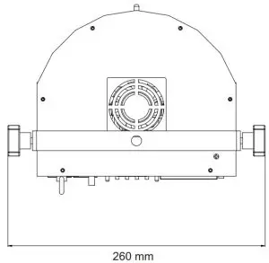
Dimension: |
Width: 26 cm |
| Depth: 19 cm | |
| Height: 19 cm | |
| Weight: | 2.30 kg |
| Laser | |
| Laser class: | Class 2M |
| Laser color: | RG |
| Laser module: | G green 35 mW 515 nm |
| R red 100 mW 650nm | |
| Remote control | |
| Battery: | 1 x Button cell 3.0 V CR2025 lithium manganese |
All information is subject to change without prior notice. © 18.05.2021
Accessories
| EUROLITE TPC-10 Coupler, silver | No. 59006856 |
| EUROLITE Safety Bond A 3x600mm up to 5kg, silver | No. 58010310 |
| EUROLITE DMX cable XLR 3pin 3m black | No. 3022785H |
| PSSO DMX cable XLR 3pin 3m black Neutrik | No. 30227810 |
| OMNITRONIC IEC Extension 3×1.0 3m black | No. 30235201 |
| EUROLITE QuickDMX USB Wireless Transmitter/Receiver | No. 70064704 |
| EUROLITE QuickDMX Wireless Transmitter/Receiver | No. 70064703 |

 report this ad
Eurolite is a brand of Steinigke Showtechnic GmbH Andreas-Bauer-Str. 5 97297 Waldbüttelbrunn GermanyD00132332 Version 1.0 Publ. 18/05/2021 ![]()
References
[xyz-ips snippet=”download-snippet”]