
EH403Z-Wave LED Floodlight withPIR Motion Detector
The EH403 is an outdoor security floodlight equipped with Z-Wave wireless communication capability. It features a PIR detector to detect motion through the movement of heat sources and a lux sensor for determining the brightness of its surroundings.
When not connected to a Z-Wave network, EH403 is fully operational as a standalone security floodlight. During hours of darkness, its PIR detector turns on the 20W floodlight when it detects movement in the protected area. Its built-in timer will then turn off the floodlight after a preset time has elapsed. During daylight hours, its lux sensor saves energy by deactivating the motion sensor and the floodlight. The lux level and the timer can be set through knobs on the device itself.
When added into a Z-Wave network, EH403 communicates directly with other end devices such as smart plugs, or report directly to a Z-Wave controller (usually a gateway). It alerts the controller when motion is detected and through Z-Wave commands, the controller can remotely turn on/off the floodlight at any time and be able to configure its lux level and timer setting.
This product supports the S2 security protocol that uses encrypted Z-Wave Plus messages to communicate to other security-enabled Z-Wave Plus products. A security-enabled Z-Wave Plus Controller must be used in order to fully utilize the security features of this product.
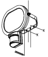
Product Overview
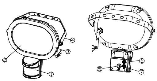
| 1. Z-Wave PIR Detector | 5. Learn Button |
| 2. Toughened glass lens | 6. Time off Knob |
| 3. Floodlight housing | 7. Lux Knob |
| 4. Mounting bracket |
Note: Please read this entire instruction manual before you start to install the floodlight.
Adding to Z-Wave Network
Connecting the PowerBefore mounting the unit on its final outdoor location, it is recommended to first power up the unit indoors in order to set up its Z-Wave connection and to perform preliminary tests.
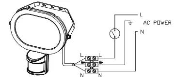
- Wire up the unit to a cable plug using a wiring fitting as shown below.Follow exactly the wire colors as below:– BROWN (Live) wire to the mains lives connection.– BLUE (Neutral) wire to the mains neutral connection.– GREEN/YELLOW wire to the mains earth cable.Auto InclusionThe unit supports the Auto Inclusion feature where it will automatically enter Inclusion mode when first powered up after a factory reset.
- Prepare the Z-Wave controller.
- Plug the cable plug into the wall socket to power up the unit. WARNING: be careful not to touch any exposed wire/contacts to prevent electrical shock!
- The Link LED will start to blink slowly with 2-second on, 2-second off (for 2 minutes) which shows the unit does not be paired.
- Within 30 seconds, put the Z-Wave Controller into inclusion mode.
- The Inclusion process should be completed when the Link LED stops blinking.Note: If you are connecting this unit to a Z-Wave Controller that utilizes the S2 security protocol, you may be asked by your controller to enter a 5-digit Device Specific Key (DSK) that is unique to each unit. This can be found in one of two places:– on the QR code label on the back of the unit– on the insert card inside the packaging.
- Turn on the floodlight using the controller to check if the auto inclusion is working properly.If Auto Inclusion fails, refer to the Troubleshooting section regarding Manual Inclusion
Mounting the Unit
Choosing the locationThe recommended location for the floodlight is outside the house under the eaves or other shaded areas where it is not directly exposed to sunlight.
– Do not aim its PIR detector facing a window or direct sunlight, otherwise poor triggering response may occur.
– Avoid aiming the PIR Detector at pools, heating vents, air conditioners or objects that may change temperature.
– Avoid aiming the PIR Detector at trees or shrubs or where the movement of pets or animals may be detected
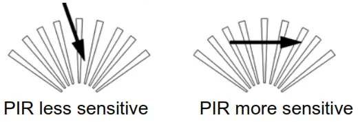
– Where possible, mount the unit so that the path of an intruder would cut across the fan pattern rather than directly towards the detector.
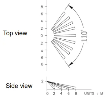
For the best results, mount the floodlight onto normal brickwork 1.8~2.0m above the ground. At this height, the unit will detect movement within its 110 degrees fan-shaped detection pattern up to 8m depending on adjustment.
SAFETY PRECAUTION
- DO NOT install when it is raining.
- Isolate the power supply before installation.
- Ensure that local Wiring and Building regulations are complied with.
- The unit is supplied with a pre-wired supply cable this must be used and must not be removed.
- Ensure that the power supply is protected by a 6amp circuit breaker or 5amp fuse.
- Ensure a minimum distance of 2.0m away from lighted objects.
- The unit must be installed vertically with the PIR at the bottom of the unit.
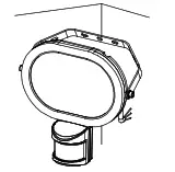
- The unit can be corner mounted if preferred.

Installation & Wiring instructions
- Use the mounting bracket to mark the position of the mounting holes.
- Drill the holes and insert suitable wall plugs
- Fix the mounting bracket to the wall using suitable screws.Wiring instructionsWARNING: Isolate the mains power supply to prevent electrical shock.
- It is recommended to add an internal single-pole wall switch to allow easy control of the unit.
- Connect the mains power supply to the pre-wired cable provided with the fitting as shown above. If the connection is made outdoors a suitable waterproof IP box must be used to make the connections.Follow exactly the wire colors as below:– BROWN (Live) wire to the mains live connection via a wall switch– BLUE (Neutral) wire to the mains neutral connection.– GREEN/YELLOW wire to a suitable earth point. The unit must be earthed.Note: Do not remove the pre-wired supply cable. This will invalidate the warranty.
- When completed, turn the knobs of Time-Off on the unit to the “T” mark, and turn the knob of Lux on the unit to the “ ” mark.
- Reinstate the power supply to the floodlight and switch on the wall switch, if installed. When the PIR is triggered, the LED of the PIR will blink once and the floodlight will turn on for around 5 seconds then turn off,. It is now in ‘test mode’.
Warm-UpIt will take approximately 5 seconds for the PIR detector to warm up after power on. During this period the floodlight will turn on. When the floodlight turns off, the warm-up procedure is complete and the PIR detector is ready.
Walk TestThe user can perform a walk test to ensure the PIR detector’s range falls within the desired area of coverage. This test also checks if the unit is still within the communication range of the Z-Wave controller.
- Walkthrough its PIR Detector coverage area. The floodlight turns on when you move and turns off after approximately 5 seconds. Wait for the floodlight to turn off before moving again to test.
- If necessary, tilt the floodlight to achieve the desired result. The floodlight may be tilted downwards by up to 30° to light the area directly under it. Tilting by more than 30° may cause issues with the lux sensor as light reflected back from the area under the floodlight may switch the lux sensor to daylight mode hence turning the floodlight off.
- When you are satisfied with the coverage area you can now set the desired Time period and Lux level.
Time and Lux adjustment
You can set desired Time period and Lux level through:(i) the Z-Wave controller if the unit is already connected to it, or(ii) manually adjusting the knobs on the unit if not connected to a Z-Wave network. The following section describes the steps for manual setting.
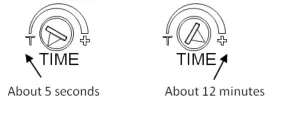
- Time adjustmentThe time-off knob controls how long the floodlight will stay on after the motion is detected. Turn the TIME control knob towards the + sign to increase how long the floodlight stays on (up to about 12 minutes) or towards the T to decrease (down to about 8 seconds). The recommended setting for Time control is approximately the midpoint of the scale (approximately 5 minutes).
- Lux adjustmentThe LUX adjustment sets the brightness level threshold that will activate the motion sensor. The Lux control can be adjusted between T (always triggered regardless of light level) and the moon symbol (triggered on only during hours of darkness). The adjustable Lux range is about 30 – 200 Lux.

- To set the lux level, turn the Time-off knob to “T” for maximum response.
- Turn the LUX control knob to the “moon” (dusk) position.
- Wait until the ambient light level reaches the level of darkness at which you wish the floodlight to activate.
- Slowly rotate the Lux knob anti-clockwise while keeping creating motion during the process until the floodlight turns on. At this position, the light will operate at approximately the same level of darkness each evening.
- Set the Time-off knob back to the desired preset time.
- When completed, tighten the two Allen screws on the side of the floodlight body to secure its positionNote: When connected to a Z-Wave controller, the manual settings will be overwritten by the settings through the Z-Wave controller.
Operation
Z-Wave GroupThe unit supports either one of two Z-Wave Association Groups:Group 1: Association with 1 Controller node.Group 2: Association with 4 nodes (i.e. end devices such as smart plugs and other lighting controllers). This allows the PIR detector on the unit to transfer commands directly to other Z-Wave end devices without the participation of the controller. This has the effect that when its detector triggers, all devices associated with the unit will be operated. The table below is control commands that can be sent from the controller. Refer to the Programming section for details on sending these commands.
|
Commands from Controller |
Commands |
| Turn on Floodlight | Switch Binary Set On/ Basic Set On |
| Turn off Floodlight | Switch Binary Set-Off/ Basic Set-Off.
Note: The floodlight will revert back to its own self-control only after this command is sent. |
| Set Timer | Configuration settings, Parameter 1 |
| Set Lux level | Configuration settings, Parameter 2 |
| Read Lux level | Multilevel sensor: 0x03 |
| Sensor Event PIR | Z-Wave commands/notification | Remark | |
| Lux sensor | sensor | ||
| Daylight | Trigger | When Trigger:
– Notification, PIR Trigger ON: Group 1 When the timer expires: – Notification, PIR Trigger OFF: Group 1 |
Z-Wave command is sent even if floodlight is off |
| Night, or Lux knob set to “T” | Trigger | When Trigger:
– Notification, PIR Trigger ON: Group 1 – Switch Binary Report: Group 1 – Basic Set On: Group 2 When the timer expires: – Notification, PIR Trigger OFF: Group 1 – Switch Binary Report: Group 1 – Basic Set-Off: Group 2 |
| Other Events | Floodlight behavior | Z-Wave commands/notification | Remark |
| 1st power on | On for 5 seconds | Notification: First Power Up: Group 1 | |
| Device Factory reset | NA | Device Reset Locally Notification: Group 1 |
Programming
Z-Wave Plus Info
| Role Type | Node Type | Installer Icon | User Icon |
| Slave Always ON | Z-Wave Plus
node |
Sensor Notification Device
Type (Home Security) |
Sensor Notification Device
Type (Home Security) |
Association Command Class
| Group | Max Node |
| 1 | 1 |
| 2 | 4 |
Version
| Protocol Library | 3 (Slave_Enhance_232_Library) |
| Protocol Version | 4.3D ( 6.71.01) |
Manufacturer
| Manufacturer ID | Product Type | Product ID |
| 0x0060 | 0x0012 | 0x0001 |
AGI (Association Group Information) Table
| Group | Profile | Command Class & Command (List) N bytes | Group Name(UTF-8) |
| 1 | General | Device Reset Locally Notification Notification Report
Binary Report Sensor Multilevel Report |
Lifeline |
| 2 | Control | Basic Set | PIR Control |
Notification Report
| Event | Type | Event | Event Parameters Length | Event Parameters |
| First power up | 0x08 | 0x01 | 0x00 | |
| PIR Trigger ON | 0x07 | 0x08 | 0x00 | |
| PIR Trigger OFF | 0x07 | 0x00 | 0x01 | 0x08 |
Switch Binary: LED Floodlight Status
| Switch Binary Report (value) | Description |
| 0x00 | Floodlight is off |
| 0xFF | Floodlight is on |
Z-Wave Configuration settings1. PIR Trigger Off period: Period to send Trigger Off command after PIR is triggered. Before this period expires, the PIR will not be able to detect any subsequent motion
| Parameter | Size | Range | Default |
| 1 | 2 | 8~720 secs | 15 |
2. Lux sensor threshold: Lux level to activate the PIR. When the lux level falls below this threshold and the PIR gets triggered, the unit emits a Basic Set Command (Value=0xFF) and turns on its floodlight. This overwrites the Lux level set by the Lux knob.
| Parameter | Size | Range | Default |
| 2 | 2 | 30~200 | 50 |
3. Lux auto report:
| Parameter | Size | Range | Default |
| 3 | 2 | 0~1440 minutes | 0(Off) |
4. Multilevel Sensor: Reads back the lux level measured. (Tolerance of ±30 lux. Level above 250 will be read back as 250)
| Sensor Type | Precision | Scale | Size | Sensor Value |
| 0x03 | 0 | 1 | 2 | <250 |
Command Classes
The module supports Command Classes including.
- COMMAND_CLASS_ZWAVEPLUS_INFO_V2
- COMMAND_CLASS_ASSOCIATION_V2*
- COMMAND_CLASS_ASSOCIATION_GRP_INFO*
- COMMAND_CLASS_TRANSPORT_SERVICE_V2
- COMMAND_CLASS_VERSION_V2*
- COMMAND_CLASS_MANUFACTURER_SPECIFIC_V2*
- COMMAND_CLASS_DEVICE_RESET_LOCALLY*
- COMMAND_CLASS_POWERLEVEL*
- COMMAND_CLASS_SECURITY
- COMMAND_CLASS_SECURITY_2
- COMMAND_CLASS_SUPERVISION*
- COMMAND_CLASS_FIRMWARE_UPDATE_MD_V4*
- COMMAND_CLASS_NOTIFICATION_V4*
- COMMAND_CLASS_SWITCH_BINARY*
- COMMAND_CLASS_SENSOR_MULTILEVEL_V7*
- COMMAND_CLASS_CONFIGURATION*
*Items marked an asterisk are secure command classes.
Troubleshooting
Table below lists typical problems encountered:
| Symptom | Possible Cause | Recommendation |
| Floodlight does not turn on for 5 seconds after power is connected. | The power is not connected properly. | Check if the wall switch is on. Confirm wiring is correct. Check supply breaker/fuse. |
| Cannot carry out
inclusion and association |
Floodlight already
paired to another Z-Wave Controller. |
Perform a factory reset. |
| Floodlight flashes on and off | The unit’s lux sensor is being triggered off by reflected light | |
| Z-Wave controller cannot communicate with the unit | Out of range. | 1. Relocate the controller closer to the unit.
2. Install a Z-Wave repeater such as smart plugs or other AC devices that can operate as a Repeater. |
| Floodlight remains on | PIR detector triggered by an unknown heat source. | 1. Check time setting
2. Cover its PIR Detector with black insulating tape. If after the timer expires and the floodlight turns off this indicates that the PIR Detector can see a moving heat source e.g: radiator, heater, boiler outlet, open window, open exterior door, or moving branches or bushes retaining heat from the daytime period. |
Manual Inclusion/Exclusion
The table below lists the several steps involved when adding or removing the unit from the Z-Wave network.
| Action/Status | Description | LED indication |
| No node ID | The Z-Wave Controller does not allocate a node ID to the unit. | 2-second on, 2-second off for 2 minutes. |
|
Auto Inclusion |
The power is applied for the first time and no node ID has been stored in the module, or after executing reset. | LED blinks rapidly during Inclusion, LED stops blinking when Inclusion is
complete. |
|
Manual Inclusion |
1. Put the Z-Wave Controller into inclusion mode. | LED blinks rapidly during Inclusion, LED stops blinking when Inclusion is complete |
| 2. Press the tamper switch 3 times within 1.5 seconds to put the unit into inclusion mode. | ||
|
Exclusion |
1. Put the Z-Wave Controller into exclusion mode. | |
| 2. Press the tamper switch 3 times within 1.5 seconds to put the unit into exclusion mode. | ||
|
Factory Reset (This procedure should only be used when the controller is inoperable.) |
1. Press the tamper switch 3 times within 1.5 seconds to put the unit into exclusion mode. | |
| 2. Within 1 second of step 1, press the tamper switch again and hold until LED is off (about 5 seconds). | ||
| 3. Node ID is excluded. The device reverts to factory default state and will be in
auto-inclusion mode for 4 minutes. |
||
| ※ Failed or successful results in including/excluding the ID can be viewed on the Z-Wave Controller. |
Specifications
| Power Requirement | 220~240V, 50/60 Hz AC |
| Power Cable Requirement | H05RN-F, 3 Core, 1.0mm² |
| Lighting Load | 20W, LED sealed unit not replaceable |
| Colour Temperature (K) | 5000 K Cool White |
| CRI | >70 |
| Lumen (Lm) | 1500 lm±5% |
| Beam angle | > 90° |
| Light Tilting Angle | Floodlight body: Vertical 0° to 30° forward tilt recommended |
| Mounting Height | Recommended 1.8 ~ 2.0m on Normal Brick Wall |
| PIR Detection area | Max. range 12m, max. angle of120° (@1.9m height, 25°C ambient temperature) |
| PIR Swivel Angle | Up to 30° Leftward, Up to 30° Rightward |
| Lux Adjustment | Approximately 30 ~ 200 Lux |
| Timer Adjustment | Approximately 8 seconds ~ 12 minutes |
| Protection Class | Class 1 – Must be earthed |
| Working Temperature | -20°C – +40°C |
| Dimension (H x W x D) | 20 cm x 19.6 cm x 8.8 cm |
| Weight | 0.8 kg |
| Protection Degree | IP54-Weather Proof |
| Frequency Range | EU: 868.42HMz / AU: 921.42HMz |
Specifications are subject to change without notice

WARNING:Do not dispose of electrical appliances as unsorted municipal waste, use separate collection facilities.
Contact your local government for information regarding the collection systems available.
If electrical appliances are disposed of in landfills or dumps, hazardous substances can leak into the groundwater and get into the food chain, damaging your health and well-being.
When replacing old appliances with new ones, the retailer is legally obligated to take back your old appliance for disposal at least for free of charge.
 report this ad
www.everspring.com50 Sect. 1 Zhonghua Rd TuchengNewTaipeiCity 236 Taiwan.
References
[xyz-ips snippet=”download-snippet”]