EVERSPRING ON OFF PLUG AN186 User Manual

The AN186 On/Off Plug is a Z-Wave Plus enabled device and is fully compatible with any Z-Wave enabled network. The device can be set up in a Z-Wave network to communicate directly with other end devices such as PIR motion detector, or to report directly to a Z-Wave controller (usually a gateway).
This product supports the S2 security protocol that uses encrypted Z-Wave Plus messages to communicate to other security-enabled Z-Wave Plus products. A security-enabled Z-Wave Plus Controller must be used in order to fully utilize the security features of this product.
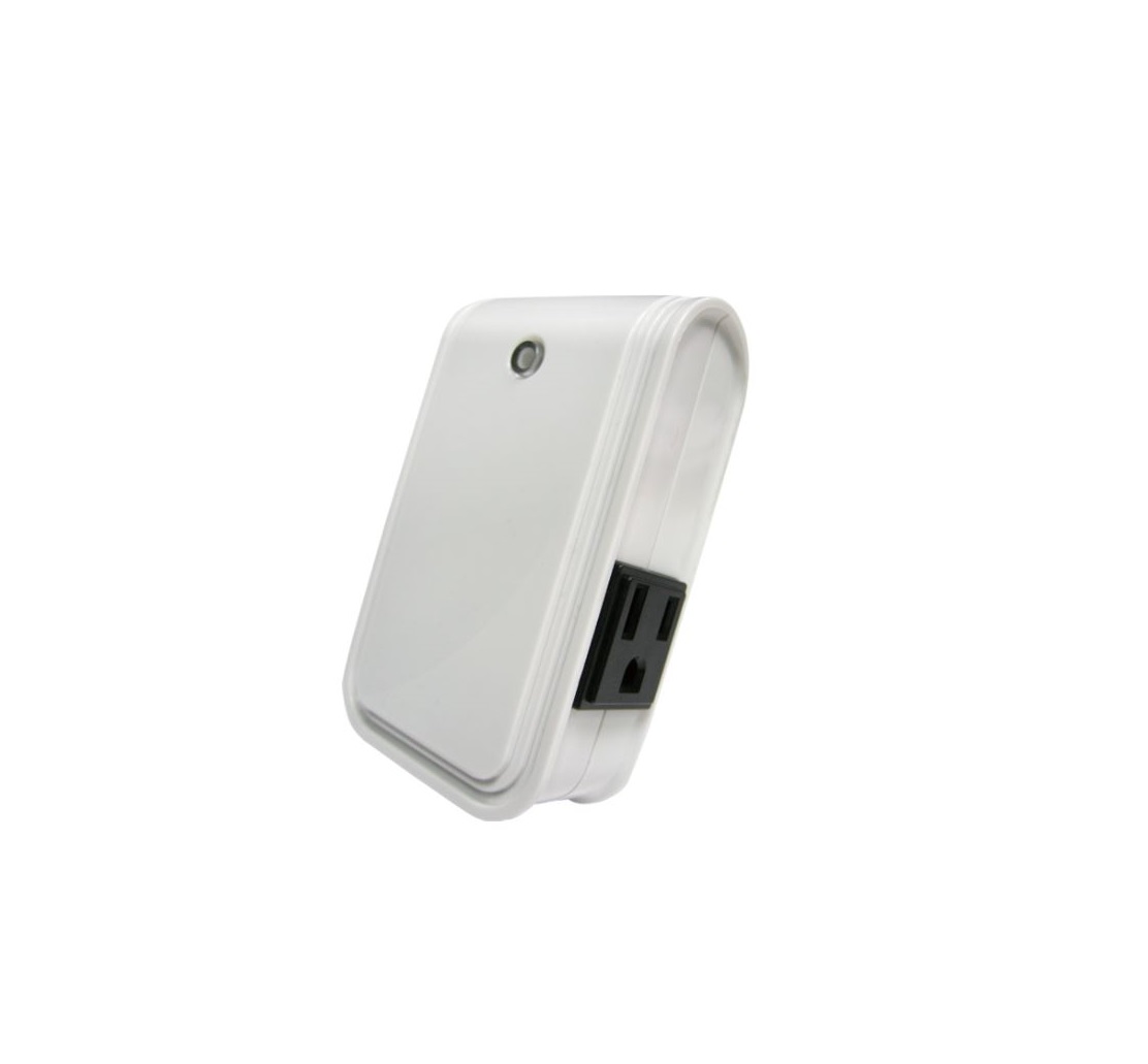
This On/Off Plug module is designed to control the on/off status of lighting and appliances in the home. Remote On/Off control of the connected load is possible even when paired with other manufacturer’s Wireless Controller. Each module is also designed to act as a repeater to re-transmit RF signal to ensure that it is received by its intended destination by routing the signal around obstacles and radio dead spots.
Product Overview
Adding to Z-Wave Network
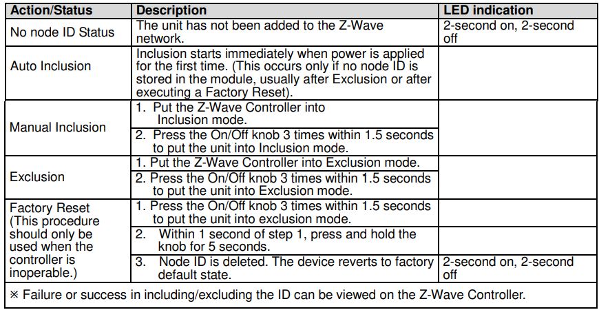
Auto Inclusion
The On/Off plug supports Auto Inclusion feature where it will automatically enter Inclusion mode when first powered up after a factory reset.
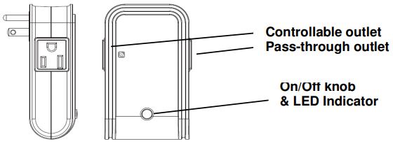
- In the front casing, there is an On/Off knob which is used to carry out inclusion, exclusion or association.
- Put a Z-Wave Controller into inclusion/exclusion mode.
- Plug this On/Off device into a wall outlet near the load to be controlled.
- The Inclusion process should be completed when the LED stops blinking.Note: If Auto Inclusion fails, refer to the Troubleshooting section regarding Manual Inclusion.
Testing
- From the Z-Wave Controller’s interface, turn on the newly added On/Off Module (refer to the Controller’s user manual for instructions). The LED indicator on the module should turn on.
- Turn off the module before connecting any appliance to it.
Installation
- Plug this On/Off Module into a wall outlet near the appliance/lighting to be controlled.
- Plug the appliance into the Controllable outlet of the module, indicated by a wireless icon printed on the module. Note: There are two outlets at opposite sides of the module. Appliances plugged into the controllable outlet can be controlled by this module whereas the other side is non-controllable and acts only as an electrical pass-through outlet. Important: Make sure the total appliance load of both sides do not exceed 1400 watts, which means if the load of controllable outlet is changed, the other side should be altered accordingly. For instance, if the load of controllable outlet is 1400 watts, the other should be 0 watt; while if the load of controllable outlet is 1100 watts, the other should be 300 watts.
- Set the switch on the appliance permanently to the ON position.
- To control the appliance manually from the module, simply press the module’s On/Off knob. When the red indicator LED turns ON (for about 5 seconds) this indicates electrical power is directed into the appliance. When the LED turns off, electrical power is cut off from the appliance.
Programming
Z-Wave Group
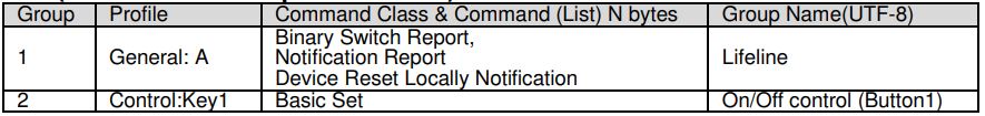
The unit supports either one of two Z-Wave Association Groups:Group 1: Association with 1 Controller node.Group 2: Association with 4 nodes (i.e. end devices such as detectors or other lighting switches).This allows the On/Off module to receive commands directly from these end devices without the participation of the controller.
Group 1 commands:
• When the unit is powered for the first time, the unit will send a Notification Report to the node ofGroup 1.• When setting the unit or changing the unit’s status, the unit will send a Binary Switch Report to the node of Group 1. When the unit is OFF, Switch Binary Report Value = 0x00. When the unit is ON, Switch Binary Report Value = 0xFF.• Device Reset: When performing Factory Reset the unit will send Device Reset Locally Notification to the node of Group1.
Group 2 commands:• When the button on the unit is pressed, the unit will send a Basic Set command to the nodes ofGroup 2. When the unit is OFF, Basic Set Value = 0x00. When the unit is ON, Basic Set Value = 0xFF.
Z-Wave Plus Info
Role TypeSlave Always On
Node TypeZ-Wave Plus node
Installer IconOn Off Power Switch
User IconOn Off Power Switch
Version
Protocol Library — 3 (Slave_Enhance_232_Library)Protocol Version — 4.60 ( 6.71.00)
Manufacturer
Manufacturer ID0x0060
Product Type0x0004
Product ID0x000C
AGI (Association Group Information) Table
Basic
- Basic Get: Inquire about the status of the device.
- Basic Report: Report the status of the device.
- Basic Set: Set the status of the device.
Notification
The device will send notifications (Notification Type =0x08, Event = 0x01) upon being powered on.
Configuration
The configurable values are as following:
Remember the last status:
Parameter Number3Size1Range1/0Default1: remember (0: do not remember)
Command Classes
The module supports Command Classes including…
- COMMAND_CLASS_ZWAVEPLUS_INFO_V2
- COMMAND_CLASS_SWITCH_BINARY*
- COMMAND_CLASS_SWITCH_ALL*
- COMMAND_CLASS_ASSOCIATION_V2*
- COMMAND_CLASS_ASSOCIATION_GRP_INFO*
- COMMAND_CLASS_TRANSPORT_SERVICE_V2
- COMMAND_CLASS_VERSION_V2*
- COMMAND_CLASS_MANUFACTURER_SPECIFIC_V2*
- COMMAND_CLASS_DEVICE_RESET_LOCALLY*
- COMMAND_CLASS_POWERLEVEL*
- COMMAND_CLASS_SECURITY
- COMMAND_CLASS_SECURITY_2
- COMMAND_CLASS_NOTIFICATION_V8*
- COMMAND_CLASS_CONFIGURATION_V2*
- COMMAND_CLASS_FIRMWARE_UPDATE_MD_V4*
*Items marked an asterisk are secure command classes.
Troubleshooting
The table below lists the several steps involved when adding or removing the unit from the Z-Wave network.
Note: If you are connecting this unit to a Z-Wave Controller that utilizes the S2 security protocol, you may be asked to enter a 5 digit Device Specific Key (DSK) that is unique to each unit by your controller. This can be found in one of two places:– on the QR code label on the back of the unit– on the insert card inside the packaging
Table below lists typical problems encountered:


Specification
Operating Voltage — AC100-120V, 50/60HzMaximum Load — 1400WRange — Up to 100 meters line of sightFrequency Range — US: 908.42 MHz JP: 922.5MHzFCC ID — FU5AN186IC — 23210-AN186
* Specifications are subject to change without notice.
![]()
Mobile of end product
Federal Communication Commission Interference Statement
This device complies with Part 15 of the FCC Rules. Operation is subject to the following two conditions: (1) This device may not cause harmful interference, and (2) this device must accept any interference received, including interference that may cause undesired operation.
This equipment has been tested and found to comply with the limits for a Class B digital device, pursuant to Part 15 of the FCC Rules. These limits are designed to provide reasonable protection against harmful interference in a residential installation. This equipment generates, uses and can radiate radio frequency energy and, if not installed and used in accordance with the instructions, may cause harmful interference to radio communications. However, there is no guarantee that interference will not occur in a particular installation. If this equipment does cause harmful interference to radio or television reception, which can be determined by turning the equipment off and on, the user is encouraged to try to correct the interference by one of the following measures:
– Reorient or relocate the receiving antenna.-Increase the separation between the equipment and receiver.-Connect the equipment into an outlet on a circuit different from that to which the receiver is connected.-Consult the dealer or an experienced radio/TV technician for help.
FCC Caution: Any changes or modifications not expressly approved by the party responsible for compliance could void the user’s authority to operate this equipment.
This transmitter must not be co-located or operating in conjunction with any other antenna or transmitter.
Radiation Exposure Statement:This equipment complies with FCC radiation exposure limits set forth for an uncontrolled environment. This equipment should be installed and operated with minimum distance 20cm between the radiator & your body.Industry Canada statement:
This device complies with ISED’s license-exempt RSSs. Operation is subject to the following two conditions: (1) This device may not cause harmful interference, and (2) this device must accept any interference received, including interference that may cause undesired operation.
Radiation Exposure Statement:This equipment complies with ISED radiation exposure limits set forth for an uncontrolled environment. This equipment should be installed and operated with minimum distance 20cm between the radiator & your body.
WARNING:Do not dispose of electrical appliances as unsorted municipal waste, use separate collection facilities. Contact your local government for information regarding the collection systems available. If electrical appliances are disposed of in landfills or dumps, hazardous substances can leak into the groundwater and get into the food chain, damaging your health and well-being. When replacing old appliances with new ones, the retailer is legally obligated to take back your old appliance for disposal at least for free of charge.
![]()
50 Sect. 1Zhonghua Rd TuchengNew Taipei City 236 Taiwan
A501112667R01
References
[xyz-ips snippet=”download-snippet”]