![]()
EVOCHARGE® Retractor –Electric Vehicle Cable Management SystemModel Number: EVC0201
![]()
Installation Guide
IMPORTANT SAFETY INSTRUCTIONS
This document contains instructions and warnings that must be followed when installing and using the Electric Vehicle Supply Equipment (EVSE). Before installing or using the EVSE, read this entire document as well as WARNING and CAUTION markings in this document.
Unpacking
Unpackage all items and confirm the contents as noted below.
| Item | Description | Qty. |
Notes |
| 1 | Retractor with Mounting Bracket | 1 | |
| 2 | Cable Clamp Package Kit | 1 | Includes one (1) CableClamp, four (4) #5 Phillips screws 5/8” long, one (1) 10-32 x 1 ¼” long scew, and one (1) 10-32 nut. |
Installation
Installation Planning
![]() WARNING: RISK OF ELECTRIC SHOCK
WARNING: RISK OF ELECTRIC SHOCK
- Do not touch live electrical parts.
- .Disconnect the power supply to the charging station and verify no power is present before installing, adjusting, or repairing the cable retractor. Failure to do so may result in physical injury or damage to the power supply system and the charging station.
The retractor must be installed only by a licensed contractor or electrician in accordance with the provisions of the local electrical industry and building construction and should comply with national building and electrical codes and standards.
Before installing, make sure you have read these instructions in this manual and fully understand its contents.Appropriate protection is required when connecting to a main panel/switchboard. The tools and parts used as outlined in the section “Tools & parts required for installation”.
Prior to mounting, determine the location of acceptable mounting support. All charging station and cable management products must be anchored into mounting support such as a 2” x 4” stud or a solid concrete wall, using mounting hardware that is appropriate for the surface on which you are mounting. DO NOT mount this unit directly to a stucco/drywall/wallboard. If installing to a wood stud, use the appropriate lag screws, minimum 2-1/2” in length, and ensure the mounting plate holes are positioned on the centerline of the stud. If mounting onto a concrete, block, or
Table 2-1 Tools & parts required for installation
|
Tool |
Size | Source of Supply |
Remark |
| Mounting Fasteners x2 | 3/8” dia. min. 2- 1/2” length | Commercially Available | For installing the Mounting Bracket & Holder to the wall/structure |
| Phillips Screwdriver | PH3 | Commercially Available | For Installation of the cable clamp |
| Flat Screwdriver | ¼” Slotted | Commercially Available | For Installation of the cable clamp |
| Wrench or Socket | 9/16” or other | Commercially Available | Size required depends on the type of lag screws used for mounting retractor to a wall stud or other structure |
Install the Retractor
- To begin the installation, install the retractor to the wall, pedestal, or mounting structure. To allow for the maximum amount of usable cable length, mount the retractor above and as close as possible to the charging station while still allowing the cable to be suspended from the ground when fully retracted.
- The mounting bracket is supplied installed to the retractor and includes (2) mounting holes (top and bottom of retractor) as shown in Figure 2-1. Use the mounting holes as a template to determine locations to install appropriate mounting fasters to the structure the retractor is being installed to.

WARNING: Prior to mounting, determine a location with acceptable mounting structural support to mount the structure. All charging station and cable management products must be anchored into a mounting structure that is approved by local codes and requirements using mounting hardware that is appropriate for the surface on which you are mounting. Please consult with a local building engineer and inspector to determine mounting structure requirements. It is the responsibility of the Installer and/or Product Owner to ensure and confirm that the installation and anchoring of the Product are in full compliance with all Building Code Requirements required of the location of the install.
- Next, install the cable sleeve/clamp around the cable and secure it with the 4 screws provided as shown in Figure 2-2. Note: before tightening slide the cable sleeve to the desired section of the cable. The desired location depends on the length of the cable and mounting height of the retractor so you may need a test fit to determine the desired length.Note: the retractor is supplied standard with the clamp shown on the left above for use with cable diameters up to 0.850”.The clamp shown on the right is for larger cable sizes and can be ordered directly from EVOCHARGE
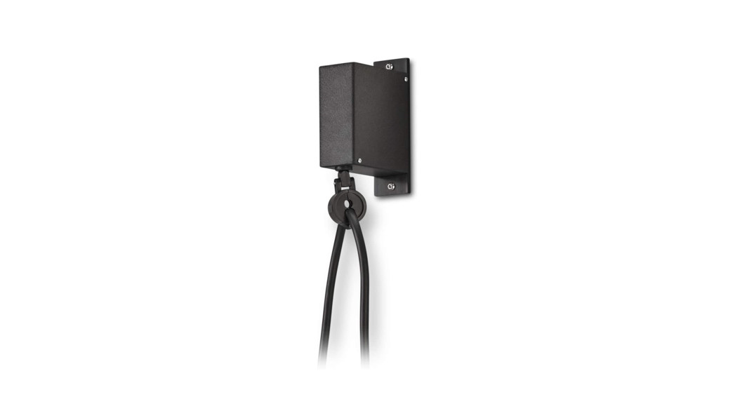
- Next, Install the Cable Clamp to the Retractor as shown below in Figure 2-3, and tighten the fastening screw. The installation is now complete. Reference Figure 2-4 below for an example of the installed product.
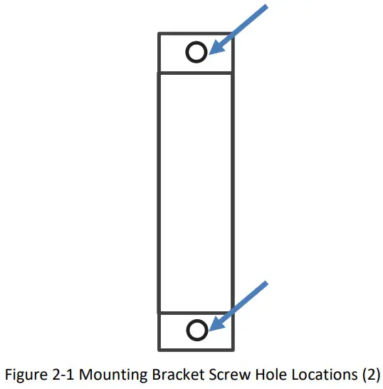

Figure 2-3 Installation of the Cable Clamp to the Retractor
 report this ad
Figure 2-4 Example of installed product
EVOCHARGE® Retractor Installation Guidewww.evocharge.com
References
[xyz-ips snippet=”download-snippet”]