
eVOLUTION R225DWS Telescopic Dry Wall Sander Instruction Manual
INTRODUCTION
(1.2) This Instruction Manual was originally written in English.
(1.3) IMPORTANT
Please read these operating and safety instructions carefully and completely. For your own safety, if you are uncertain about any aspect of using this equipment please access the relevant Technical Helpline, the number of which can be found on the Evolution Power Tools website. We operate several Helplines throughout our worldwide organization, but Technical help is also available from your supplier.
WEB www.evolutionpowertools.com
(1.4) Congratulations on your purchase of an Evolution Power Tools Machine. Please complete your product registration ‘online’ as explained in the A5 online guarantee registration leaflet included with this machine. You can also scan the QR code found on the A5 leaflet with a Smart Phone. This will enable you to validate your machine’s guarantee period via Evolutions website by entering your details and thus ensure prompt service if ever needed. We sincerely thank you for selecting a product from Evolution Power Tools.
EVOLUTION LIMITED GUARANTEE.Evolution Power Tools reserves the right to make improvements and modifications to the product design without prior notice.
Please refer to the guarantee registration leaflet and/or the packaging for details of the terms and conditions of the guarantee. The guarantee below is applicable to machines destined for the UK mainland market only. Other markets may have specific requirements, additions or exclusions applied. Consult your dealer for details of the guarantee applied in your area/country. All Evolution guarantees are in addition to your statutory rights.
(1.5) Evolution Power Tools will, within the guarantee period, and from the original date of purchase, repair or replace any goods found to be defective in materials or workmanship. This guarantee is void if the tool being returned has been used beyond the recommendations in the Instruction Manual or if the machine has been damaged by accident, neglect, or improper service. This guarantee does not apply to machines and / or components which have been altered, changed, or modified in any way, or subjected to use beyond recommended capacities and specifications. Electrical components are subject to respective manufacturers’ warranties. All goods returned defective shall be returned prepaid freight to Evolution Power Tools. Evolution Power Tools reserves the right to optionally repair or replace it with the same or equivalent item. There is no warranty – written or verbal – for consumable accessories such as (following list not exhaustive) blades, cutters, drills, chisels or paddles etc. In no event shall Evolution Power Tools be liable for loss or damage resulting directly or indirectly from the use of our merchandise or from any other cause. Evolution Power Tools is not liable for any costs incurred on such goods or consequential damages. No officer, employee or agent of Evolution Power Tools is authorized to make oral representations of fitness or to waive any of the foregoing terms of sale and none shall be binding on Evolution Power Tools.
Questions relating to this limited guarantee should be directed to the company’s head office, or call the appropriate Helpline number.
MACHINE SPECIFICATIONS
|
MACHINE |
METRIC | IMPERIAL |
| Motor (230-240V ~ 50Hz) | 710W |
3A |
|
Speed No Load |
600-1500min-1 | 600 1500rpm |
| Weight | 5.8kg |
12.8lb |
|
Dust Port Diameter |
35mm | 1-5/16 In. |
| Tool Dimensions – Contracted (H x W x L) | 230 x 250 x 1450mm |
9 x 13-13⁄16 x 57-1/16 In. |
|
Tool Dimensions – Extended (H x W x L) |
230 x 250 x 1970mm |
9 x 13-13⁄16 x 77-9/16 In. |
|
Cable Length |
4m |
13ft 1-7⁄16 In. |
|
Hand Arm Vibration |
230V: Ah,DS, w= 3,75m/s2 |
|
|
Sound Pressure Level LPA: |
230V: 88dB(A)K=3 dB(A) |
|
|
Sound Power Level LWA: |
230V: 99dB(A)K=3 dB(A) |
|
SANDING AREA CAPACITIES |
METRIC |
IMPERIAL |
|
Sanding Pad Diameter |
215mm |
8-7/16 In. |
|
Sanding Disc. |
8 In. |
Handling
- Handle the machine with care, allowing the machine to do the work.
- Avoid using excessive physical effort on any of the machines controls.
- Consider your security and stability, and the orientation of the machine during use.
Work Surface
- Consider the work surface material; its condition, density, strength, rigidity and orientation.
WARNING: The vibration emission during actual use of the power tool can differ from the declared total value depending on the ways in which the tool is used. The need to identify safety measures and to protect the operator are based on an estimation of exposure in the actual conditions of use (taking account of all parts of the operating cycle, such as the times the tool is switched off, when it is running idle, in addition to trigger time).
(1.8)LABELS & SYMBOLS
WARNING: Do not operate this machine if warning and/or instruction labels are missing or damaged. Contact Evolution Power Tools for replacement labels. Note: All or some of the following symbols may appear in the manual or on the product.
(1.9)
|
Symbol |
Description |
|
V |
Volts |
|
A |
Amperes |
|
Hz |
Hertz |
|
min-1 |
Speed |
|
~ |
Alternating Current |
|
no |
No Load Speed |
|
Wear Safety Goggles |
|
|
Wear Ear Protection |
|
|
|
Wear Dust Protection |
|
Read Instructions |
|
|
CE Certification |
|
|
Double Insulated |
|
|
Triman – Waste Collection & Recycling |
|
|
Waste Electrical & Electronic Equipment |
|
|
|
Warning |
(1.10) INTENDED USE OF THIS POWER TOOL
WARNING: This product is a Hand Held Dry Wall Sander and has been designed to be used in conjunction with a dust extraction and collection system. Only use accessories designed for use in this machine and/or those recommended specifically by Evolution Power Tools Ltd.
When fitted with appropriate abrasive paper this machine can be used for sanding:Dry Walls.Dry Ceilings.Dry Floors.It can also be used to remove paint coatings, adhesive and loose plaster etc
PROHIBITED USE OF THIS POWER TOOL
WARNING: This product is a Hand Held Dry Wall Sander and must only be used as such. It must not be modified in any way, or used to power any other equipment or drive any other accessories other than those mentioned in this Instruction Manual.
WARNING: This machine must NOT be used on any surface which is suspected to contain lead or asbestos.
If the presence of either of these substances is even suspected, have the work-place inspected by the appropriate local authority department. Lead can be found in some old painted surfaces, and is highly toxic when disturbed.
Asbestos is highly dangerous and has to be dealt with by highly trained and specially equipped removal teams. Consult your local authority for further advice and guidance.
SAFETY PRECAUTIONS
(1.13) WARNING: This machine is not intended for use by persons (including children) with reduced physical, sensory or mental capabilities, or lack of experience and knowledge, unless they have been given supervision or instruction concerning the safe use of the machine by a person responsible for their safety and who is competent in its safe use.
Children should be supervised to ensure that they do not have access to, and are not allowed to play with, this machine.
(1.14) ELECTRICAL SAFETY
This machine is fitted with the correct moulded plug and mains lead for the designated market. If the mains lead or the plug are damaged in any way, they must be replaced with original replacement parts by a competent technician.
(1.15) OUTDOOR USE
WARNING: For your protection if this tool is to be used outdoors it should not be exposed to rain, or used in damp locations. Do not place the tool on damp surfaces. Use a clean, dry workbench if available. For added protection use a residual current device (R.C.D.) that will interrupt the supply if the leakage current to earth exceeds 30mA for 30ms. Always check the operation of the residual current device(R.C.D.) before using the machine.
If an extension cable is required it must be a suitable type for use outdoors and so labelled. The manufacturers instructions should be followed when using an extension cable.
(2.1) POWER TOOL GENERAL SAFETY INSTRUCTIONS
(These General Power Tool Safety Instructions are as specified in BS EN 60745-1:2009 & EN 61029-1:2009)
WARNING: Read all safety warnings and instructions. Failure to follow the warnings and instructions may result in electric shock, fire and/ or serious injury.
Save all warnings and instructions for future reference.
The term “power tool” in the warnings refers to your mains-operated (corded) power tool or battery-operated (cordless) power tool.
(2.2) 1) General Power Tool Safety
Warnings [Work area safety]a) Keep work area clean and well lit. Cluttered or dark areas invite accidents.
b) Do not operate power tools in explosive atmospheres, such as in the presence of flammable liquids, gasses or dust. Power tools create sparks which may ignite the dust or fumes.
c) Keep children and bystanders away while operating power tool. Distractions can cause you to lose control.
(2.3) 2) General Power Tool Safety
Warnings [Electrical Safety]a) Power tool plugs must match the outlet. Never modify the plug in any way. Do not use any adapter plugs with earthed (grounded) power tools. Unmodified plugs and matching outlets will reduce the risk of electric shock.
b) Avoid body contact with earthed or grounded surfaces, such as pipes, radiators, ranges and refrigerators. There is an increased risk of electric shock if your body is earthed or grounded.
c) Do not expose power tools to rain or wet conditions. Water entering a power tool will increase the risk of electric shock.
d) Do not abuse the cord. Never use the cord for carrying, pulling or unplugging the power tool. Keep cord away from heat, oil, sharp edges or moving parts. Damaged or entangled cords increase the risk of electric shock.
e) When operating a power tool outdoors, use an extension cord suitable for outdoor use. Use of a cord suitable for outdoor use reduces the risk of electric shock.
f) If operating a power tool in a damp location is unavoidable, use a residual current device (RCD) protected supply. Use of an RCD reduces the risk of electric shock.
(2.4) 3) General Power Tool Safety
Warnings [Personal Safety].a) Stay alert, watch what you are doing and use common sense when operating a power tool. Do not use a power tool while you are tired or under the influence of drugs, alcohol or medication.A moment of inattention while operating power tools may result in serious personal injury.
b) Use personal protective equipment. Always wear eye protection. Protective equipment such as dust masks, non-skid safety shoes, hard hat or hearing protection used for appropriate conditions will reduce personal injuries.
c) Prevent unintentional starting. Ensure the switch is in the off-position before connecting to power source and or battery pack, picking up or carrying the tool. Carrying power tools with your finger on the switch or energising the power tools that have the switch on invites accidents.
d) Remove any adjusting key or wrench before turning the power tool on. A wrench or key left attached to a rotating part of a power tool may result in personal injury .
e) Do not overreach. Keep proper footing and balance at all times. This enables better control of the power tool in unexpected situations.
f) Dress properly. Do not wear loose clothing or jewellery. Keep your hair, clothing and gloves away from moving parts. Loose clothes, jewellery or long hair can be caught in moving parts.
g) If devices are provided for the connection of dust extraction and collection facilities, ensure that these are connected and properly used. Use of dust collection can reduce dust-related hazards.
(2.5) 4) General Power Tool Safety
Warnings [Power tool use and care].
a) Do not force the power tool. Use the correct power tool for your application.The correct power tool will do the job better and safer at a rate for which it was designed.
b) Do not use the power tool if the switch does not turn it on or off. Any power tool that cannot be controlled with the switch is dangerous and must be repaired.
c) Disconnect the power tool from the power source and/or battery pack from the power tool before making any adjustments, changing accessories, or storing power tools. Such preventative safety measures reduce the risk of starting the power tool accidentally.
d) Store idle power tools out of the reach of children and do not allow persons unfamiliar with the power tool or these Instructions to operate the power tool. Power tools are dangerous in the hands of untrained users.
e) Maintain power tools. Check for misalignment or binding of moving parts, breakage of moving parts and any other condition that may affect the power tools operation. If damaged, have the power tool repaired before use. Many accidents are caused by poorly maintained power tools.
f) Keep cutting tools sharp and clean. Properly maintained cutting tools with sharp cutting edges are less likely to bind and are easier to control.
g) Use the power tool, accessories and tool bits etc. in accordance with these instructions, taking into account the working conditions and the work to be performed. Use of the power tool for operations different from those intended could result in a hazardous situation.
(2.6) 5) General Power Tool Safety
Warnings [Service]a) Have your power tool serviced by a qualified repair person using only identical replacement parts. This will ensure that the safety of the power tool is maintained.
(2.7) HEALTH ADVICE
WARNING: When using this machine, dust particles may be produced. In some instances, depending on the materials you are working with, this dust can be particularly harmful. If you suspect that paint on the surface of material you wish to cut contains lead, seek professional advice. Lead based paints should only be removed by a professional and you should not attempt to remove it yourself. Once the dust has been deposited on surfaces, hand to mouth contact can result in the ingestion of lead. Exposure to even low levels of lead can cause irreversible brain and nervous system damage. The young and unborn children are particularly vulnerable.
You are advised to consider the risks associated with the materials you are working with and to reduce the risk of exposure. As some materials can produce dust that may be hazardous to your health, we recommend the use of an approved face mask with replaceable filters when using this machine.
You should always:
- Work in a well-ventilated area.
- Work with approved safety equipment, such as dust masks that are specially designed to filter microscopic particles.
(2.8) WARNING:
the operation of any power tool can result in foreign objects being thrown towards your eyes, which could result in severe eye damage. Before beginning power tool operation, always wear safety goggles or safety glasses with side shields or a full face shield where necessary.
ADDITIONAL SAFETY INSTRUCTIONS
WARNING: Read completely all safety instructions. Failure to follow these instructions could result in serious personal injury. Pass these instructions on to any other operators and ensure that they are adequately trained in the use and adjustment of this machine.
- Read the Instruction Manual completely and carefully. Learn the applications and limitations, as well as the specific potential hazards relating to the use of this machine. Pass this manual on to any other operator(s) who may use this machine.
- Wear safety glasses or a face shield when operating this machine. Everyday spectacles do not have impact resistant lenses and therefore cannot be regarded as safety glasses.
- Protect your lungs. Wear a dust mask that is capable of filtering microscopic dust particles.
- Wear close fitting work clothing, and remove any dangling jewellery, chains or belts etc that could become entangled in rotating machinery.
- Protect your hearing. Wear suitable ear defenders.
- Inspect the machines power cord regularly, and if it is damaged in any way have the cord replaced with a genuine replacement part fitted by a qualified technician.
- Check for any other damage. Any damage found must be repaired before the machine is used again. Check for misalignment or binding of moving parts, and any condition that may affect the machines operation. Any replacement parts should be Evolution Power Tool approved, and fitted by a qualified and competent technician.
- Check for any missing parts. Any missing parts must be replaced with genuine replacement parts and fitted by a qualified technician.
- Do not abuse the power cord. Do not use the power cord to carry the machine or to pull the plug from the power outlet.
- Keep the power cord away from heat sources, oil, sharp edges, and always be aware of the power cords routing within the workplace.
- Do not use this machine while tired or under the influence of drugs, alcohol or medication (consult your Doctor).
- Any extension cord used with this machine must be in good condition and capable of carrying the current required to operate this machine safely and efficiently.
- Ensure that the workplace is adequately illuminated.
- Do not allow familiarity with this machine to make you careless or to ignore basic workshop safety protocols. A careless fraction of a second could be sufficient to cause severe injury.
- Keep the work area well ventilated. If possible open some windows and put an exhaust fan in one of them to move air from the inside to the outside.
- Use a dust extraction and collection machine that is compatible with this machine. Follow the instructions provided by the manufacturer of the dust extraction machine.
- Check to ensure that the mains supply is the same as the voltage given on the machines rating plate.
- Remove the power cord plug from the mains supply outlet when changing an abrasive disc or carrying out any other maintenance procedures and/or adjustments.
(4.1) GETTING STARTED
UNPACKING
Caution: This packaging contains sharp objects. Take care when unpacking. Remove the machine, together with the accessories supplied from the packaging. Check carefully to ensure that the machine is in good condition and account for all the accessories listed in this manual. Also make sure that all the accessories are complete. If any parts are found to be missing, the machine and its accessories should be returned together in their original packaging to the retailer. Do not throw the packaging away; keep it safe throughout the guarantee period. Dispose of the packaging in an environmentally responsible manner. Recycle if possible. Do not let children play with empty plastic bags due to the risk of suffocation.
(4.2) ITEMS SUPPLIED
|
Description |
Quantity |
|
Instruction Manual |
1 |
|
Drywall Sander |
1 |
|
Oval Extension Tube |
1 |
| Flexible Dust Extraction Hose with integral protection stand |
1 |
|
Hose End Connectors (1 x Fitted, 2 x Supplied) |
3 |
|
Auxiliary ‘D’ Handle |
1 |
|
Circular Abrasive Sanding Discs (Assorted Grits) |
6 |
|
Allen Keys (S5 & S6) |
1 |
|
Carbon Brushes |
1 pair |
MACHINE OVERVIEW
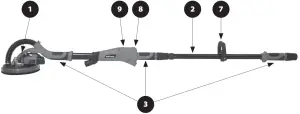
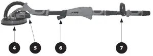
- SWIVELLING SANDING HEAD
- EXTENSION TUBE
- HAND GRIP AREAS
- LED RING LIGHT
- MOTOR
- LED PROJECTOR LIGHT
- AUXILIARY D HANDLE
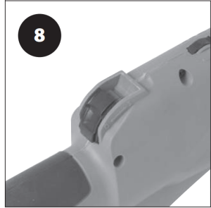
- MOTOR ‘ON/OFF’ SWITCH

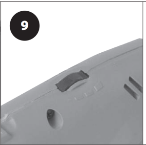
- MOTOR SPEED CONTROL
- HOSE END CONNECTORS (X3)
- DUST EXTRACTION HOSE

ASSEMBLY AND PREPARATION
SHORT REACH MODEWARNING: Only conduct the following procedures with the machine disconnected from the main power supply. Fitting the Flexible Dust Extraction Hose.
- Loosen the sleeve nut. (Fig. 1)Fig. 1
- Insert the Flexible Dust Extraction Hose into the machines main dust extraction tube/handle, and push it fully ‘home’. (Fig. 2)Fig. 2
- Tighten the sleeve nut to fasten the Flexible Extraction Hose into the machine.
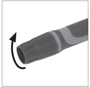 Fig. 1
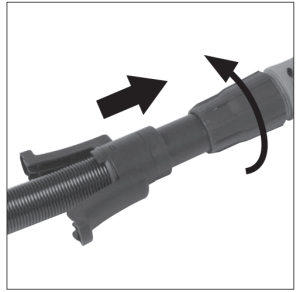 Fig. 2
Note: The integral protection stand allows the machine (when not in use) to be stood upright against a wall or similar. The Flexible Hose is protected from being crushed or kinked by the stand. (Fig. 3)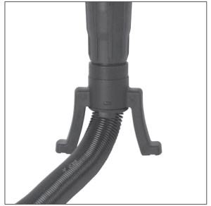 Fig. 3
LONG REACH MODE
- Loosen the sleeve nut. (Fig. 1)
- Remove the Flexible Dust Extraction Hose if fitted.
- Slide the Extension Tube into the machines main dust extraction tube/handle.Note: The Extension Tube which slides into the main dust extraction/handle of the machine has a slightly oval crosssection. To help insertion and correct location of the Extension Tube, gently rotate it as you push it into place.
- Slide the Extension Tube into the main dust extraction/ handle until the 1.9m pictogram just disappears from view.
- Slide the Extension Tube Ferrule up and into the main extraction tube/handle. (Fig. 4)Fig. 4
- Tighten the sleeve nut to secure the Extension Tube and ferrule into their service positions. (Fig. 5)Fig. 5
- Fit the ‘D’ handle clamp around the Extension Tube. Note: This clamp is hinged. By removing the pinch bolt (Fig. 6) the clamp can be ‘opened’ and placed around the Extension Tube. The clamp can then be ‘closed’ around the Extension Tube, the pinch bolt replaced and tightened to secure the clamp in place.Fig. 6
- Fit the ‘D’ handle to the clamp using the two (2) socket headed hex screws.Note: We recommend that the ‘D’ Handle clamp is positioned directly behind and is touching the Extension Tube ferrule. This locates the ‘D’ handle in the most convenient position for the majority of operators.Note: The design of the ‘D’ handle is such that ergonomic positioning of the handle on the clamp is possible. This ensures comfortable operation for both right-handed and left-handed users.
- Insert the Flexible Extraction Hose fully into the end of the Extension Tube and tighten the sleeve nut to secure it in place. (Fig. 7)Fig. 7
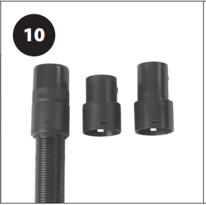
- The ‘free’ end of the Dust extraction Hose can now be connected to a suitable dust extraction and collection machine.Note: Follow the instructions provided by the manufacturer of the dust extraction machine being used.Note: A selection of Hose End Connectors is provided. These should ensure that this machine can be connected to most commercially available dust extraction machines.
- To Change a Hose End Connector
- Locate the two (2) ‘lugs’ which fit into the two (2) ‘notches’ in the Hose End Mounting Ring.
- Using a flat bladed screwdriver, gently and carefully press the ‘lugs inwards, and at the same time ease the Mounting Ring away from the Hose End Connector. The Hose End Connector will release from the Mounting Ring.
- Snap a new Hose End Connector onto the Mounting Ring.
- Check that the ‘lugs’ have deployed into the ‘notches’.
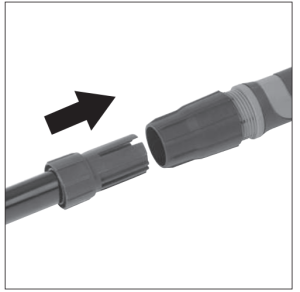 Fig. 4
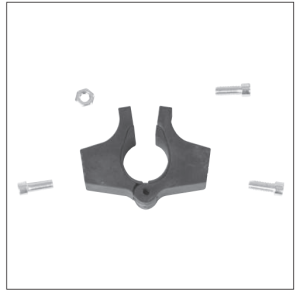 Fig. 6
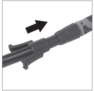 Fig. 7
ATTACHING AN ABRASIVE DISC TO THE SANDING PAD
Note: The Motor Driven Sanding Pad located in the swivelling Sanding Head of the machine, is fitted with a ‘hook and loop’ attachment system.The ‘loops’ on the back of the abrasive discs engage with the ‘hooks’ on the surface of the Sanding Pad.
To attach an abrasive disc:
- Ensure that the Sanding Pad is clean and free from any dirt or debris.
- Press the new abrasive disc onto the Sanding Pad with the palm of a hand.
Ensure that the holes in the new abrasive disc align with the dust extraction ports in the Sanding Pad. (Fig. 8)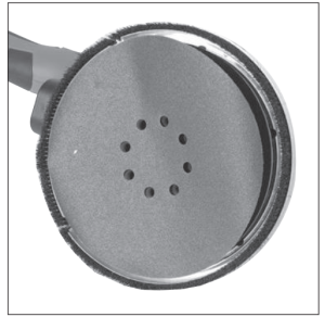 (Fig. 8)
To remove an abrasive disc:
- Simply grip the edge of the abrasive disc and gently peel it from the Sanding Pad.
THE MACHINES CONTROLS
- The ‘ON/OFF’ slide switch (Fig.9) is a latching type. Slide it forward to start the motor. Push forward and down on the central section of the switch to latch it in the ‘ON’ positionFig.9
- Push down on the rear central section of the slide switch to release the switch and turn the motor ‘OFF’. The switch will automatically return to the ‘OFF’ position
- The speed control dial (Fig. 10) is located forward of the ‘ON/OFF’ switch. Rotate this control dial to alter the speed of the motor.Fig. 10
- The Sanding Head LED Light switch is positioned on top of a housing located to the RH (Right Hand) side of the Sanding Head casing. (Fig. 11a)Fig. 11 aThis light will provide illumination to the immediate area being worked upon.
- The LED Projector Light (Fig. 11b). The ‘ON/OFF’ Rocker switch is located on the body of the light, underneath and to the rear. This Light will provide extra illumination to the area about to be worked upon.Fig. 11 b
- A ring located just to the front edge of the integral protection stand can be rotated slightly.
- Rotating this ring will reveal an air bleed port. (Fig. 12)Fig. 12
- Revealing this air bleed port in part or in full, allows the operator to adjust the airflow from the Sanding Head to a connected dust extraction machine.
- The operator should adjust this control to give the most effective dust extraction from the Sanding Head.WARNING: Even with an effective dust extraction/collecting machine attached to this machine the operator should still employ all relevant PPE procedures and processes. If working ‘on site’ consult the person responsible for Health & Safety on the site for extra guidance.
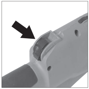 Fig.9
Fig.9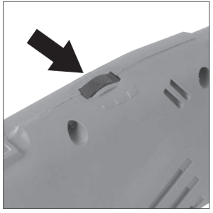 Fig. 10
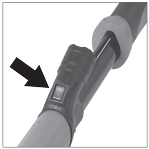 Fig. 11 aThis light will provide illumination to the immediate area being worked upon.
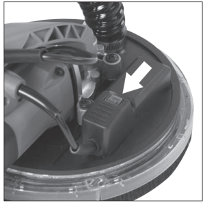 Fig. 11 b
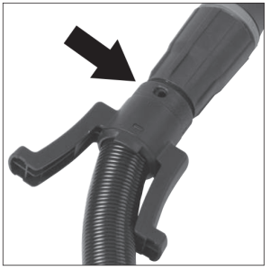 Fig. 12
OPERATIONAL GUIDANCE AND ADVICE
Body and Hand Positioning
- This machine is a two (2) handed machine. Soft grip hand hold areas are provided along the machine.
- An auxiliary ‘D’ handle is provided and is particularly useful when the machine is configured in Long Reach Mode.
- Position your hands along the machine to provide the best and most comfortable combination of ‘reach’ and ‘leverage’ for the particular operation being undertaken.
- Keep your hands away from the swivelling Sanding Head.
- Do not stretch or overbalance. Reposition yourself so that you do not have to stretch.
Caution: If ‘reach’ or access considerations necessitate the use by the operator of a stand-on platform, such a platform must be suitable, in good condition with all the safety features serviceable and stable in use e.g. a folding inside scaffold or ‘hop-on’ work platform.WARNING: The operator must NEVER overstretch.
THE ARTICULATED SANDING HEAD
The Sanding Head is attached to the main body of the machine by a type of Universal Joint. This allows the Sanding Head to swivel in multiple directions.
When in use the abrasive disc can effectively ‘float’ over the work surface. This action enables the operator to sweep the work surface from top to bottom or from side to side with minimal changes to their stance and foot position. This affords greater security and better balance for the operator.
SANDING
Operational Advice
- Configure the machine to the ‘Reach Mode’ required.
- Connect the required Sanding Head to the machine.
- Connect a suitable dust extraction and collection machine to the Drywall Sander.
- Turn on the extraction unit.
- Adopt a comfortable stance holding the Sander by the two most convenient and comfortable hand grips.
- Turn on the Sanding Head LED Light.
- Turn on the Sander, and if required the projector LED Light.
- Position the Sanding Head lightly against the work surface, and apply just enough pressure to align the Sanding Head with the work surface.
- Gently apply more pressure to engage the abrasive disc onto the work surface.
- Move the Sander across the work surface in long overlapping sweeps. Apply only enough pressure to keep the abrasive disc flat against the work surface. Excessive pressure should be avoided as it can cause swirl marks and unevenness in the work surface.
- Keep the Sander in constant motion whilst the abrasive disc is in contact with the work surface. Use a steady, sweeping motion, allowing the rotating abrasive disc to ‘float’ over the work surface. Moving the Sander erratically or concentrating for too long on one area can also cause swirl marks or unevenness in the work surface.WARNING: Do not allow the rotating abrasive disc to contact sharp objects such as protruding nails, screws etc or architectural wall fittings such as electrical boxes or switch plates etc. Damage to the Sander or the wall fittings could result.
MAINTENANCE
The Sanding Head Brush Skirt (Fig. 13)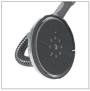 Fig. 13The Brush Skirt surrounds the Sanding Pad to which the abrasive discs are applied. The Brush Skirt serves two (2) main purposes:
- It extends below the surface of the abrasive discs so that it contacts the work surface first, orientating the Sanding Head. This helps prevent the rotating abrasive disc from ‘gouging’ the work surface on first contact.
- It helps contain the dust particles within the swivelling Sanding Head until the airflow from an attached extraction machines sucks the dust away.
Over time, depending upon the frequency of use and the type of material sanded, the bristles on the Brush Skirt will become degraded and worn. The bristles on the Brush Skirt must be complete with no gaps or portions missing.
A new Brush Skirt has a bristle length of approximately 15mm. Replace the Brush Skirt when the length of the bristles is approximately 8mm, or when the bristles no longer extend below the surface of an installed sanding disc.
To replace the Brush Skirt
WARNING: Only attempt this procedure with the machine disconnected from the mains power supply.
- Remove any attached abrasive disc to reveal the Sanding Pad and the centrally located Hex Headed Socket Screw that attaches the Pad to the motors drive spindle.
- Holding the Sanding Pad with the palm of one hand (Fig. 14), insert the supplied 5mm Hex Key into the head of the central screw. Loosen and remove the screw. Remove the Sanding Pad from the motors drive spindle.Fig. 14
- Use a cross-head screwdriver and remove the six (6) self tapping screws and the special fixing clips. (Fig. 15) that secure the Brush Skirt and lens into the Sanding Head.Fig. 15
- Carefully pull and ease the Brush Skirt and lens from the Sanding Head.Installation of a new Brush Skirt is basically the reversal of the removal process.
- During installation of a new Brush Skirt take care to not over tighten the six (6) self tapping screws. These should be firmly tightened but be careful not to strip the threads within the tapped holes.
- Ensure that the special fixing clips are correctly positioned.
- Reinstall the Sanding Pad on the motors drive spindle and secure in place with the Hex Headed Socket Screw.
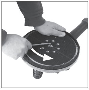 Fig. 14
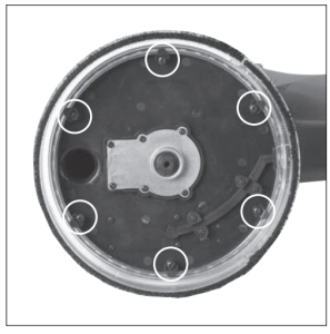 Fig. 15
Note: Changing the Brush Skirt will expose the interior of the Sanding Head. The operator should take the opportunity to examine, clean and remove any debris from within the Sanding Head, or from the exhaust ports and exhaust tubes fastened or contained within it.
(6.1) WARNING: Any maintenance must be carried out with the machine switched off and disconnected from the mains/ battery power supply. Check that all safety features and guards are operating correctly on a regular basis. Only use this machine if all guards/safety features are fully operational.All motor bearings in this machine are lubricated for life. No further lubrication is required. Use a clean, slightly damp cloth to clean the plastic parts of the machine. Do not use solvents or similar products which could damage the plastic parts.
WARNING: Do not attempt to clean by inserting pointed objects through openings in the machines casings etc. The machines air vents should be cleaned using compressed dry air. Excessive sparking may indicate the presence of dirt in the motor or worn out carbon brushes.
(6.2) If this is suspected have the machine serviced and the brushes replaced by a qualified technician.
(6.4) ENVIRONMENTAL PROTECTION
Waste electrical products should not be disposed of with household waste. Please recycle where facilities exist. Check with your Local Authority or retailer for recycling advice.
EC DECLARATION OF CONFORMITYIn accordance with EN ISO 17050-1:2004
The manufacturer of the product covered by this Declaration is:UK: Evolution Power Tools Ltd, Venture One, Longacre Close, Holbrook Industrial Estate, Sheffield, S20 3FR.FR: Evolution Power Tools SAS, 61 Avenue Lafontaine, 33560, Carbon-Blanc, Bordeaux, France.The manufacturer hereby declares that the machine as detailed in this declaration fulfils all the relevant provisions of the Machinery Directive and other appropriate directives as detailed below.The manufacture further declares that the machine as detailed in this declaration, where applicable, fulfils the relevant provisions of the Essential Health and Safety requirements.
The Directives covered by this Declaration are as detailed below:
2006/42/EC. Machinery Directive.2014/30/EU. Electromagnetic Compatibility Directive2011/65/EU. & The Restriction of the Use of certain Hazardous2015/863/EU. Substances in Electrical Equipment (RoHS) Directive.2012/19/EU. The Waste Electrical and Electronic Equipment (WEEE) Directive.
And is in conformity with the applicable requirements of the following documents:
EN 60745-1: 2009+A11: 2010, EN 60745-2-3: 2011+A2: 2013 +A11: 2014+ A13: 2015,PAH Requirement AfPS GS 2019:01 PAK,EN ISO 12100: 2010, EN 55014-1: 2017,EN55014-2:2015, EN61000-3-2:2014, EN61000-3-3:2013, EK9-BE-88:2014
Product DetailsDescription: R225DWS 225mm Dry Wall SanderEvolution Model No: 078-0001 / 078-0002 / 078-0003 / 078-0004Brand Name: EVOLUTIONVoltage: 230V ~ 50/60 HzInput: 710W
The technical documentation required to demonstrate that the product meets the requirements of directive has been compiled and is available for inspection by the relevant enforcement authorities, and verifies that our technical file contains the documents listed above and that they are the correct standards for the product as detailed above.
Signed: Print: Matthew Gavins: Group Chief Executive.
Date: 01/04/2016
Name and address of technical documentation holder.UK: Evolution Power Tools Ltd, Venture One, Longacre Close, Holbrook Industrial Estate, Sheffield, S20 3FR.FR: Evolution Power Tools SAS, 61 Avenue Lafontaine, 33560, Carbon Blanc, Bordeaux, France.
UKEvolution Power Tools LtdVenture OneLongacre CloseHolbrook Industrial EstateSheffieldS20 3FR+44 (0)114 251 1022
USEvolution Power Tools LLC8363 Research DriveDavenportIowa52806+1 866-EVO-TOOL
EUEvolution Power Tools SAS61 Avenue Lafontaine33560Carbon-BlancBordeaux+ 33 (0)5 57 30 61 89


 Discover Evolution Power ToolsVisit: www.evolutionpowertools.com or downloadthe QR Reader App on your smart phone and scanthe QR code (Right).
 WEB: www.evolutionpowertools.com
References
[xyz-ips snippet=”download-snippet”]