![]()

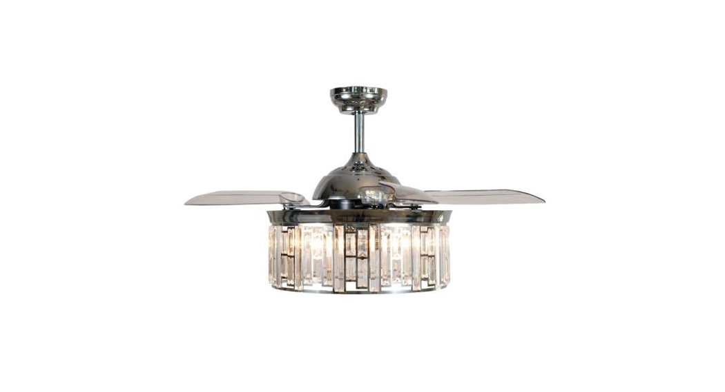
Size:148x210mm42"Fan CeilingUser manual
WYJSFL4203ACCXE26120 V~ 60 Hz 34 W (MOTOR) 5xE26 25 W Max. (Not included)
SAFETY TIPS
OBSERVE THE FOLLOWING: READ AND SAVE THESE INSTRUCTIONSWARNING: TO REDUCE THE RISK OF FIRE, ELECTRIC SHOCK, OR PERSONAL INJURY, MOUNT TO OUTLET BOX MARKED ‘ACCEPTABLE FOR FAN SUPPORT OF 35 LBS(15.9 KG) OR LESS’ AND USE MOUNTING SCREWS PROVIDED WITH THE OUTLET BOX AND/OR SUPPORT DIRECTLY FROM BUILDING STRUCTURE. MOST OUTLET BOXES COMMONLY USED FOR THE SUPPORT OF LUMINAIRES ARE NOT ACCEPTABLE FOR FAN SUPPORT AND MAY NEED TO BE REPLACED. CONSULT A QUALIFIED ELECTRICIAN IF IN DOUBT.
- Installation work and electrical wiring must be done by a qualified person(s) in accordance with all applicable codes and standards (ANSI/NFPA 70), including fire-rated construction.
- Use this unit only in the manner intended by the manufacturer. If you have any questions contact the manufacturer.
- After making the wire connections, gently push connections into outlet box with wire nuts pointing up. The wires should be spread apart with the grounded conductor and the equipment-grounding conductor on one side of the outlet box and the ungrounded conductor on the other side of the outlet box.
- Before you begin installing the fan, switch power off at service panel and lock service disconnecting means to prevent power from being switched on accidentally. When the service disconnecting means cannot be locked, securely fasten a prominent warning device, such as a tag, to the service panel.
- Be cautious! Read all instructions and safety information before installing your new fan. Review the accompanying assembly diagrams.
- When cutting or drilling into wall or ceiling, do not damage electrical wiring and other hidden utilities.
- Make sure the installation site you choose allows the fan blades to rotate without any obstructions.Allow a minimum clearance of 7 feet from the floor to the trailing edge of the blade.
- To reduce the risk of fire, electric shock, or personal injury, this fan must be mounted to an outlet (Mounting must support at least 35 lbs.)
- WARNING! Do not bend blade holders during installation to motor, balancing or during cleaning. box marked suitable for fan support, and use the mounting screws provided with the outlet box.Do not insert foreign object between rotating blades.
- Attach the mounting bracket using only the hardware supplied with the outlet box. Fan is only to be mounted to an outlet box marked “Acceptable for Fan Support”.
- WARNING! To reduce the risk of fire or electric shock, do not use this fan with any solid state fan speed control device, or variable speed control.
- If this unit is to be installed over a tub or shower, it must be marked as appropriate for the application.
- NEVER place a switch where it can be reached from a tub or shower.
- The combustion airflow needed for safe operation of fuel-burning equipment may be affected by this unit’s operation. Follow the heating equipment manufacturer’s guideline safety standards such as those published by the National Fire Protection Association (NFPA), and the American Society forHeating, Refrigeration and Air Conditioning Engineers (ASHRAE) and the local code authorities.
- Before servicing or cleaning unit, Switch power off at Service panel and lock service disconnecting means to prevent power from being switched on accidentally. When the service disconnecting means cannot be locked, securely fasten a prominent warning device, such as a tag, to the service panel.
- All set screws must be checked and re-tightened where necessary before installation.
- Keep electrical appliances out of reach of children or infirmed persons. Do not let them use the appliances without supervision.
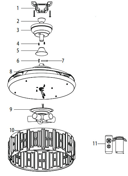
PART LIST
| # | Description |
| 1 | Mounting Bracket |
| 2 | Downrod |
| 3 | Canopy |
| 4 | Canopy Screws |
| 5 | Coupling Cover |
| 6 | Clamp pin |
| 7 | Cross pin |
| 8 | Fan Motor Assembly |
| 9 | Light kit |
| 10 | Lamp Shade |
| 11 | Remote Control |
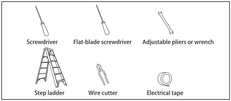
TOOLS REQUIRED (NOT INCLUDED)
FEATURES
DOWNROD INSTALLATION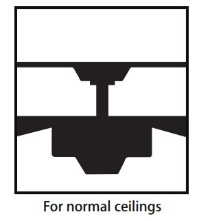 PREPARING FOR INSTALLATION
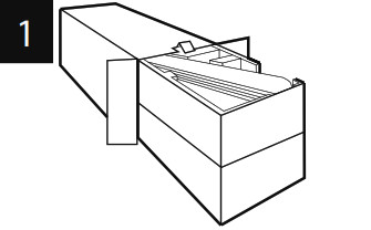 |
Unpack and inspect fan carefully to be certain all contents are included. |
 |
Turn off power at fuse box to avoid possible electrical shock. |
 |
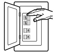
Use metal outlet box suitable for fan support (must support 35 lbs). Before attaching fan to outlet box, ensure the outlet box is securely fastened by at least two points to a structural ceiling member (a loose box will cause the fan to wobble). |
MOUNTING BRACKET INSTALLATION
 |
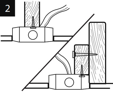
Install mounting bracket (1) to outlet box in ceiling using the screws and washers provided with the outlet box. |
MOUNTING OPTIONS
Choose aMOUNTING OPTION
NORMAL DOWNROD OPTIONIf installing downrod supplied with fan, proceed to page 7, step 5.
NORMAL DOWNROD OPTION
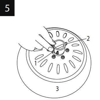 |
Remove clamp pin (1) and cross pin (2) from fan motor assembly (3). |
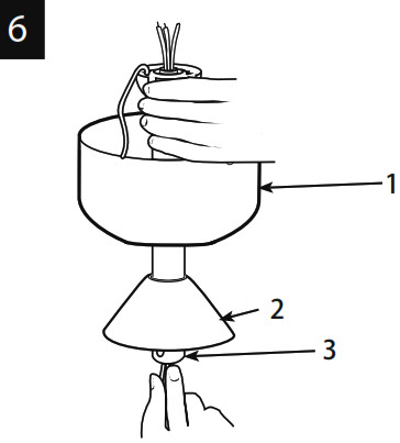 |
Place downrod (3) into canopy (1) and coupling cover (2). Feed motor wires through the downrod assembly (3). |
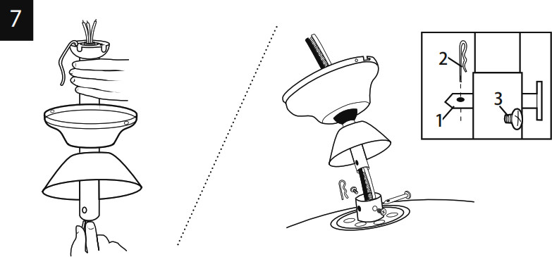 |
Feed motor lead wires through download/canopy assembly and insert download into download yoke. Make sure to align the hole in the downrod with the hole in the downrod yoke.Install yoke cross pin (1) through yoke and download. Insert clamp pin (2) into cross pin until it snaps into place. Tighten set screws (3) in yoke. |
MOUNTING
 Carefully lift fan assembly onto mounting bracket. Rotate fan until notch on downrod ball (1) engages the ridge on the mounting bracket (2). This will allow for hands-free wiring.
SAFETY CABLE INSTALLATION
 For Canadian installation and for USA fan and light kit combinations over 35 lbs, the safety cable must be installed into the house structure beams. Make sure that when the safety cable is fully extended the leadwires are longer than the cable and no stress is placed on the lead wires.Note: If Installing The Secondary Support Safety Cable in the U.S., Do Not Remove Knockouts In The Outlet Box.
WIRING OPTIONS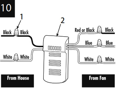 Make wiring connections from the house and the fan to the remote receiver (2) as shown. Connect using wire nuts (1) (provided). Make sure that all exposed wiring is secured inside wire nuts. Refer to Point 3 of Safety Tips on page 2.
MOUNTING Once wiring step has been completed, slide the wired remote receiver in between the bracket and the top of the downrod ball.
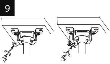
SECURE TO CEILING
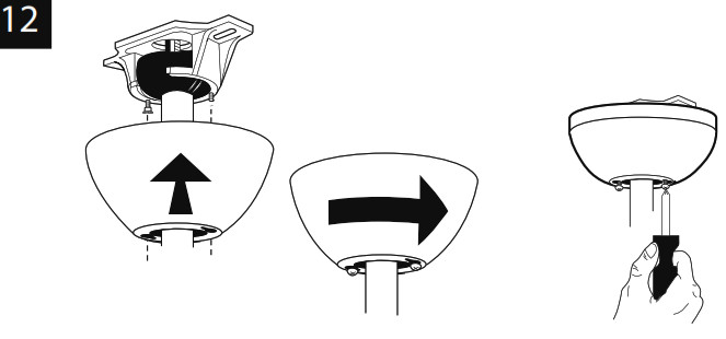
Loosen the 2 screws on the bottom of mounting bracket but do not remove them. Raise the canopy up and align the keyholes on the bottom of the canopy with the 2 screws on the bottom of mounting bracket. Rotate the canopy until both screws from the mounting bracket drop into the slot recesses. Tighten screws securely.
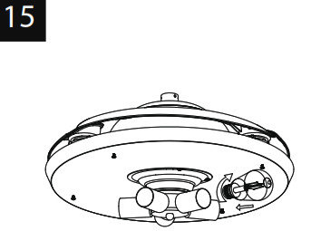
LIGHT FIXTURE INSTALLATION
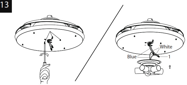 |
Remove the three mounting screws for the light kit pan identifiedMake wiring connections from the fan motor assembly to the light kit as shown. Connect using wire nuts (1) (provided).Make sure that all exposed wiring is secured inside wire nuts. |
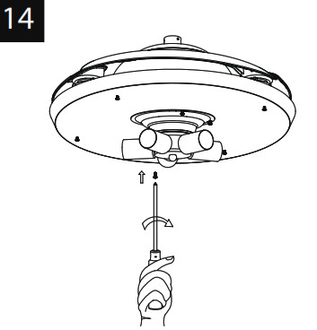 |
Install the 3 screws removed from the light kit pan (step # 13) into the closed hole in the light kit. Tighten all the screws to complete attach ment of the light kit. |
 |
Install light bulbs (not included). |
 |
Remove the 4 fixing screws from the light kit pan. Keep them for next step.The metal cage has 4 slots. Raise up the metal cage by aligning the 4 slots to the 4 round holes from the light kit pan. Install the 4 screws removed previously into the round holes of the light kit pan and tighten all 4 screws securely. |
BRACKET OF TRANSMITTER INSTALLATION
![]()
Note: Install a 23A 12V batteries by removing battery cover on back of transmitter, installing batteries, and replacing battery cover. If desired, install the transmitter holder onto the wall with included screws.
HOW TO OPERATE YOUR CEILING FAN

Restore electrical power to the outlet box by turning on the electricity at the main fuse box. To make the fan operational, open battery door by pressing and sliding down the battery door. Install a 23A 12V batteries into the hand-held remote transmitter(if not used for long periods of time, remove the batteries to prevent damage to the transmitter).
- The remote control adopts RF wireless digit emission technique, biunique controlled, coincident code rate is less than one-millionth.
- The transmitter and receiver are pre-matched at the factory. Please follow below step#3 if they don’t work well.
- Turn off the fan power and then restore it, press and hold the “fan stop” button for 3 seconds, within 10 seconds after you restore the power, then you’ll hear a beep sound from the fan, with the light flashestwice, which means the pairing process is completed.(NOTE: The pairing process is not accepted after 10 seconds when you restore supply power)
- Please note that the transmitter can pair with multiple receivers. When the transmitter does not control the receiver, please check if any similar remote controls are working nearby, disconnect them, and then proceed with pairing process again.
- Store the remote transmitter away from excessive heat or humidity.
- Battery of low power or not-used for long time should be replaced.
REMOTE CONTROL
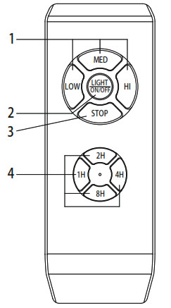
The remote buttons function as follows:
- Turn On the fan and contrd the speed= low speed= medium speed= high speed
- Light On/Off – Press and release
- Fan Stop – Press and release
- Fan timer function1H = 1hour2H = 2hours4H = 4 hours8H = 8 hours.
Maintenance
- Because of the fan′s natural movement, some connections may become loose. Check the support connections, brackets, and blade attachments twice a year. Make sure they are secured.
- Clean your fan periodically to help maintain its new appearance over the years. Do not use water when cleaning. This could damage the motor, or the wood, or possibly cause electrical shock.
- Use only a soft brush or lint-free cloth to avoid scratching the finishing. The plating is sealed with a lacquer coating to minimize discoloration or tarnishing.
- There is no need to oil your fan. The motor has permanently lubricated bearings.
TROUBLESHOOTING GUIDE
If you have difficulty operating your new ceiling fan, it may be the result of incorrect assembly, installation, or wiring. In some cases, these installation errors may be mistaken for defects. If you experience any faults, please check this troubleshooting chart. If a problem cannot be remedied, please consult with your authorized qualified and do not attempt any electrical repairs yourself.
| TROUBLE | SUGGESTED REMEDY |
| 1. If fan does not start: |
1. check main and branch circuit fuses or circuit breakers.2. check wire connections as performed in step #10 of installation.CAUTION: Make sure main power is turned off.3. Make sure forward/reverse switch is firmly in up or down position. Fan will not operate when switch is in the middle.4. If the fan still will not start, contact a qualified electrician. Do not attempt to troubleshoot internal electrical connections yourself. |
| 2. If fan sounds noisy: |
1. check to make sure all screws in motor housing are snug (not overtightened).2. check to make sure the screws which attach the fan blade holder to the motor are tight.3. Some fan motors are sensitive to signals from Solid State variable speed controls.DO NOT USe a Solid State variable speed control.4. Allow “break-in” period of 24 hours. Most noises associated with a new fan will disappear after this period. |
| 3. If fan wobbles: |
All blades are weighed and grouped by weight. Natural woods vary in density which could cause the fan to wobble even though all blades are weight-matched. The following procedures should eliminate most of the wobble. check for wobble after each step.1. check that all blades are screwed firmly into blade holders.2. check that all blade holders are tightened securely to motor.3. Make sure that canopy and mounting bracket are tightened securely to ceiling joist.4. If blade wobble is still noticeable, interchanging two adjacent (side by side) blades can redistribute the weight and possibly result in smoother operation. |
| 4. If light does not work: | 1. check to see that the wire connections in the switch housing are connected.2. check for faulty light bulbs.3. If light kit will still not operate, contact a qualified electrician for assistance. |
[xyz-ips snippet=”download-snippet”]