Extreme Flight 104″ MXS-EXP ARF Assembly Manual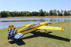
Please take a few moments to read this instruction manual before beginning assembly. We have outlined a fast, clear and easy method to assemble this aircraft and familiarizing yourself with this process will aid in a quick, easy build.Please read the following paragraph before beginning assembly of your aircraft! THIS IS NOT A TOY! Serious injury, destruction of property, or even death may result from the misuse of this product. Extreme Flight is providing you, the consumer, with a very high quality model aircraft component kit, from which you, the consumer, will assemble a flying model. It is beyond our control to monitor the finished aircraft you produce. ExtremeFlight RC will in no way accept or assume responsibility or liability for damages resulting from the use of this user assembled product.This aircraft should be flown in accordance with the AMA safety code. It is highly recommended that you join the Academy of Model Aeronautics in order to be properly insured and operate your model at AMA sanctioned flying fields only. If you are not willing to accept ALL liability for the use of this product, please return it to the place of purchase immediately.Extreme Flight RC, Ltd. guarantees this kit to be free of defects in materials and workmanship for a period of 30 DAYS from the date of purchase. All warranty claims must be accompanied by the original dated receipt. This warranty is extended to the original purchaser of the aircraft kit only.Extreme Flight RC in no way warranties its aircraft against flutter. We have put these aircraft through the most grueling flight tests imaginable and have not experienced any control surface flutter. Proper servo selection and linkage set-up is absolutely essential. Inadequate servos or improper linkage set up may result in flutter and possibly the complete destruction of your aircraft. If you are not experienced in this type of linkage set-up or have questions regarding servo choices, please contact us at [email protected] or 770-887-1794. It is your responsibility to ensure the airworthiness of your model.
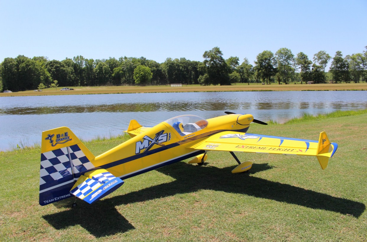
Congratulations on your purchase of the Extreme Flight RC 104 inch MXSEXP ARF! The MXS is loaded with unique features, including first rate hardware, components and thorough instructions to ensure a trouble free assembly and set-up. Weight saving components are used throughout, such as carbon fiber structural reinforcement, carbon fiber wing and stab mounting tubes, carbon fiber landing gear, titanium pushrods and a carbon fiber tail wheel assembly, all ensuring the lightest, most high performance aircraft possible. You will notice there is a box built into the bottom of the MXS fuselage. This is a pipe tunnel and will accommodate most canister mufflers and tuned pipes sold for the current makes of 100-120cc gas engines.The performance ability of the Extreme Flight RC MXS-EXP is phenomenal!This sleek, fast and agile airframe is completely unlimited in its ability to perform the full range of full stall high alpha maneuvers and aggressive gyroscopic tumbling maneuvers. The MXS is rewriting the rule book on ultraaggressive 3D maneuvers! Unrivaled in pitch and yaw authority, the MXS will be the machine that introduces a whole new level of gyroscopic gyrations and insane tumbles to the hardcore 3D masses. Rock solid in all aspects of current 3D maneuvers, the MXS will give those that fly on the bleeding edge the confidence and capability to push through and break new ground in expanding the rapidly evolving 3D flight envelope. Utilizing the same lightweight interlocking laser cut construction and carbon reinforcement as our Extra, the MXS is capable of handling the most punishing maneuvers imaginable. We have spent a great deal of time and effort to provide you, the discriminating aerobatic enthusiast, with the highest quality, most complete package possible. We are very proud of the end result of our labor and wish you great success with the assembly and flying of your Extreme Flight RC 104 inch MXS!
Hobby knife with #11 blades.Fresh 30 minute epoxy. Pacer Z-Poxy has worked very well for us for many years.Blue and Red Loctite.Electric drill with an assortment of small drill bits.Small flat head and Phillips head screw drivers.Standard and needle nose pliers.Side cutters.Metric ball driver or allen key set. (especially 2.5 and 4mm drivers) Sanding block and sandpaper.7 400oz (min) torque servos. (8 servos if you use 2 rudder servos)1 x standard size servo for the throttle.4 x Extreme Flight 1.5” single aluminum Servo Arms for the ailerons2 x Extreme Flight 2” single aluminum arms for the elevators (3 if using a tail mounted rudder servo and 4 for double tail rudders servos)1 x Extreme Flight 4” double offset aluminum arm for the rudder if using pull pull rudder setup.2 x 6” for inboard aileron Extreme Flight 20 AWG Servo Extensions (may not need any if your servo lead is at least 12”).3 X 24″ Extreme Flight 20 AWG Servo Extensions (2 outboard ailerons 1 for throttle).2 x 48”- 60” Servo Extensions. If you need to remove the stabs for transport use 54”-60″. May need 3 or 4 if using tail mounted rudder servo(s).5” Extreme Flight carbon fiber Ultimate Spinner, 85cc-120cc gas engine and recommended prop.Engine standoffs, 1.125” length if using the recommended DA120Some type of engine mufflers (stock, canisters or tuned pipes and headers) Receiver, batteries, switches, EF Flowmaster 34 ounce fuel tank and tubing.
Tips for Success:
- Before starting assembly, take a few minutes to read the entire instruction manual to familiarize yourself with the assembly process.
- Go over all the seams on the aircraft with a covering iron on a medium heat setting. Also, due to climate changes, wrinkles may develop in the covering. These are easily removed with a little bit of heat. Use a 100% cotton tee-shirt and your heat gun and heat the covering while gently rubbing the covering onto the wood with the t-shirt. Be careful not to use too much heat as the covering may shrink too much and begin to lift at the edges. Take your time, and a beautiful, paint-like finish is attainable.
- Apply CA to high stress areas such as servo mounting trays, landing gear mounts, anti-rotation pins, wing and stab root ribs, and motor box joints etc.
- By the time your aircraft arrives at your door step, it will have been handled by a lot of people. Occasionally, there are small dings or imperfections on some of the surfaces. An effective method to restore these imperfections to original condition is to use a very fine tipped hypodermic needle and inject a drop of water under the covering material and into the ding in the wood. Apply heat to the area with a sealing iron and the imperfection will disappear. Deeper marks may require that this process be repeated a couple of times to achieve the desired result, but you will be surprised at how well this technique works.
- Use high quality, fresh epoxy for installing the composite control horns and hinges. We highly recommend Pacer Z-Poxy 30 minute Epoxy as well as Pacer Hinge Glue. We are very pleased with the results and ease of application and cleanup of these products.
- Take the time to properly balance and trim your aircraft and set up rates with exponential values. Your flying experience will be greatly enhanced once your plane is properly dialed in.
- Extreme Flight now has their own Vimeo channel. There are many assembly videos providing extreme detail on certain aspects of the assembly of this very model produced by Extreme Flight team pilot Jeff Williams.
Let’s Begin:
- Locate the wing panels/ailerons and horizontal stabilizers/elevators and associated hardware bags. We will begin by hinging all of these at one time. I suggest you scuff/rough the surface of the hinges, they are slick from the manufacturing process and the glue will adhere better to a non-slick surface.Using 100-150 grit sandpaper works well to do this, be sure you don’t sand the barbs off the hinge, you just want a little scuffing on the hinge, do not sand at the pivot. I strongly recommend 30 minute (or slower curing) epoxy for installing hinges. I have found it easier to apply 3-5 drops of glue in the hinge hole and then using a toothpick, or similar, spread the glue around the sides of the hinge hole. Do this on just one side, either the wing or aileron it does not matter which is first. Mix only enough glue to work with one panel at a time.Before applying any glue to the hinge itself, I highly recommend you protect the hinge pin (pivot point) from glue. I use Vaseline, but tape will work however it is harder to remove later, in any case apply either protectant to the center of the hinge so glue cannot penetrate that pin, it will cause binding.Once you have the holes lathered with glue, apply a small amount to the hinge barbs and insert into the hinge hole twirling it as you insert it until the pin is even with the hinge line. Be sure your hinge pivots freely and is perpendicular to the hinge line. Allow to dry then mate to the appropriate surface (wing to aileron/horizontal stabilizer to elevator) and allow that to dry. Refer to figure 1 for the 3 clipped horizontal stabilizer hinges, all other hinges are normal length.
 Figure 1
 - . Install the control horns for the ailerons, be sure to note that the outer horns are the ones with the upper hole and the inner horns have it located nearer the middle (Figure 2). Once you have them inserted into the holes I advise you temporarily install the 3mm bolt and ball link, this is only to keep the control horns spaced properly and evenly, remove them once the glue is dry. You may also install the elevator control horns at this time. Be sure to scuff the bottom portion of the control horn that inserts into the hole in the control surface. Trial fit the base plate and control horn before gluing, sometimes balsa pieces and/or dust will be down in the hole and need cleaned to allow the control horn and base plate to fit down flush on the surface. (You should not have to trim the portion of the control horns that fit into the holes.)Once you have this be sure to trim the covering around the base plate but not beyond the base plate. Install the aileron servos and orient the output shaft of the servo towards the hinge line and install all the pushrods/ball links for the ailerons. To do this use the 3mm bolt and washer thru the control horn, then the ball link in the middle, then thru the other control horn, then the washer and nylon insert nut onto the other side with blue thread lock, nothing goes between the control horns except the ball link, no washers are necessary.Then hook it to your servo arm in the same manner and use blue thread lock.See Figures 3 & 4.Scuff this portion onlyFigure 2Figure 3Figure 4
- Install the elevator servos, orient the output shaft toward the hinge line of the horizontal stabilizer. It will be easier to install the servo arms after mounting the servo. Make all hookups for the pushrods/ball links as we did in the previous step. See Figure 5.Figure 5
- Hinge the rudder and install the control horns using the same technique(s) as the wing.Then you can mate the rudder to the vertical stabilizer. See Figures 6 & 7.Figure 6
- Mount your rudder servo in the rear (Figure7) or the center mount location just aft of the wing tube inside the fuselage which will require a pull pull setup (hardware is included). If you are running stock mufflers a rear mounted direct drive servo setup works great for CG purposes.If you want to run cans or pipes you can still use an aft mount servo setup and then mount your Receiver/ignition batteries further forward if necessary.Otherwise mounting the batteries in the same location/tray as the rudder servo will work. See appendix A in the aft portion of this manual for a pull pull installation.Figure 7
- Next we will install the main landing gear, axles, tires, wheel pants and wheel cuffs. Now is the time to decide whether you are going to install the wheel cuffs. If you do go with the cuffs then slide the black tubing and use either Welders adhesive, Amazing goop or CA will work too. Install this tubing on the open ended portion of the cuff since it will rest against the fuselage, tape is very handy to hold the tubing in place. I recommend you start on the back of the cuff and then wrap the tubing around so your slice is locate in the rear of the cuff and allow this to dry. Slide them onto the gear before proceeding with the tires/axles.I feel it is easier to mount the axles/tires/wheel pants before installing the gear onto the fuselage, however you could install the gear first then the axles/tires/wheel pants. Proceed with your preferred order and use the landing gear hardware bag. Now consider grinding a flat spot on the axles to accommodate the wheel collar, this provides a small flat surface to fasten the set screw against providing better holding power. Only grind a very small amount, you should barely be able to see the flat spot, grinding anymore will weaken the axle, therefore if you are not comfortable skip this technique. Now fasten the axle to the landing gear by pushing the axle thru the hole then tightening the nylon insert nut to the axle, be careful to not overtighten. If you ground a flat spot I find it best to position that facing the bottom so future wheel collar retightening is more accessible. Now install one wheel collar, the tire then the other wheel collar but don’t tighten. Now position the wheel pant onto the axle and determine the exact position of the inner and outer wheel collars such that the tire will not rub against the wheel pant. Once you have this location add blue thread lock to the set screw and tighten your wheel collars, do this to the tires on each side of the gear in the exact same manner.Now position the wheel pant(s) onto the axle/gear and tighten with the 3mm bolts/washers and use blue thread lock on these as well. Now use something to support the fuselage and install the gear onto the bottom of the fuselage with the remaining 4mm bolts, washers and nuts, see figures 8, 9 & 10.NOTE: I found it easiest to put my hand thru the pipe tunnel to support the nylon insert nuts during tightening of these four bolts/washers, but you can also use the access holes near the tank mount area.Once this is all complete now align your cuffs to the fuselage such that they are barely touching the fuselage and glue them in place, blue tape is helpful to keep them in place until the glue is dry. Again see figure 11.Figure 8Figure 9Figure 10Figure 11
- Locate your tailwheel package and have the fuselage supported to aid in this installation step. Begin by drilling a 1/8” hole centered in the bottom of the rudder approximately 3” aft of the rudder hinge line. Then insert the white ball link that will support the tiller arm and use 30 minute epoxy (suggest roughening the ball link for better adhesion). Now mount the carbon fiber tailwheel gear using the 3 bolts/washers and blue thread lock. If you are comfortable grinding flat spots on the gear then now is the time to do that. Take the tailwheel gear and grind small flat spots for the wheel collars (such as we did with the main gear axles) and another flat spot on the upper portion of the wire that will insert into the tiller housing. You will notice on the tiller housing there are two set screws, the lower is for the tailwheel wire and the upper is for the tiller arm. Insert the tiller housing into the tailwheel bracket and tighten the nylon insert nut onto the bottom side of the tailwheel bracket. Once you have the flat spots then install the tiller arm thru the eyelet of the ball link. Now install a wheel collar on the tailwheel wire and insert the tailwheel wire up thru the gear bracket and into the tiller housing and tighten, also tighten that wheel collar at the bottom of the tailwheel bracket and be sure to use blue thread lock on all set screws. See figures 12 & 13Figure 12Tailweel bracketTiller armTiller housingFigure 13
- Locate your motor and we will begin the mounting process, 1.125” standoffs will work perfectly for the DA120. If you are using a different motor then plan on needing 7.25″ from the firewall to the front of the cowling, you may want toadd 1/8″ for spinner backplate to front of the cowling clearnance/spacing for an overall distance of 7.375”.I will focus on the DA120, this motor is 6.25” overall so I used 1.125” standoffs to yield my desired spacing. You could use more or even less, but I recommend about .125” of spinner backplate clearance. You will need to use ¼” allen head bolts of about 2” to 2.5” length, depending on the amount of threads you want exposed on the inside of the firewall. I also recommend nylon inserts nuts, with washers and red thread lock for mounting the motor.Once you have mounted the motor, you may install your desired exhaust system at your discretion, however I recommend following step 9 before any exhaust is installed. See figures 14 & 15.Figure 14Figure 15
- Install the throttle servo, depending on your choice of setup and enginebrand you may have to drill a hole/slot thru the firewall to access the throttle arm on the carburetor from your servo. With the DA120 motor we mounted the servo upright in the engine box and cut a small slot in the firewall for the throttle pushrod. I again chose to file a very small flat spot on the included throttle pushrod to accommodate the bolt in the easy connector. When installing the easy connector be sure the round nut is not too tight and to use blue thread lock. It depends on being able to swivel, the ball link end to the carburetor installs just like the other connections you have already performed. Lastly be sure there will no rubbing or binding between the throttle setup and the cowling or exhaust you choose. Again refer to figures 16& 17.Figure 16Slot thru firewallPushrodEasy swivel connectorRound nutFigure 17Slot thru firewallBall linkWasherNut
- Trial fit the engine cowling to determine fit and any cutting of clearance holes. With stock mufflers you will have to cut the cowling, using headers/pipes/canister mufflers you will likely not need to cut the cowling for clearance. Determine any cooling holes and cut accordingly. There is no way I could cover every scenario, so I have only included pictures of my cowling with stock mufflers. In my setup you will not see any cooling holes in the cowling, I cut holes in the bottom of the fuselage, these are easily accessed and can be seen by looking down the pipe tunnel and deciding which cutouts to use. If you use pipes/canister mufflers then you will have to use the cutout in the pipe tunnel for access and cooling. See figures 18 & 19 for cowling cutouts.Figure 18Figure 19Small hole for accessto high and lowneedles oncarburetor.Typical slot cuts forstock mufflers
- The basic assembly is complete, now figure where you want to install the switches (there are precut holes just aft of the cowling). Install your tank in the tray just in front of the wing tube and secure with velcro/zip ties and put foam under tank. Install any other components you plan to use at this time. Figure 20 shows where I installed my electronics and accessories.Figure 20Receiver switchIgnition switchReceiver/ignition batteriesAircraft receiverFuel tank fuel dotSecond receiver battery
- Install your batteries in the rudder tray, now determine your center of gravity. The desired range is:Forward limit CG – front of wing tube Most desirable CG – Midpoint of wingtube to trailing edge of wing tube Aft limit CG –up to .5″ behind the trailing edge of the wing tube Move your batteries to achieve desired CG in this range. One way to test your CG is to fly inverted and see if it climbs or descends. If it climbs while inverted you are tail heavy, if it descends quickly you are nose heavy. We typically fly a plane that exhibits a slight descent while inverted, such that a small amount of down elevator is required for level flight. This CG seems to fit most styles of aerobatic flying, a rear CG is not required for 3D flight. Also while upright pitch to a 45°upline and fly for about a 100’ then roll inverted and see if the plane will hold that same line. If it climbs it is tail heavy and if it pitches down quickly it is too nose heavy, but it may pitch slightly down but only after holding that 45° line for some time, then exhibit a slight descent.
- Once you have the desired CG you are ready to fly. Be sure to follow allAMA safety codes to include your local flying field rules.Below are some recommended startingthrows in degrees:Low: middle/medium: HighElevator 20: 45: 55Aileron 25: 32: 38Rudder 2″ L/R As desired for middle and high rates but don’t touch the elevatorsExpo 30-35 35-45 40-50*NOTE* rudder low throw is measured at the bottom most aft portion of the rudder. A high quality digital angle/throw meter will provide a more accurate setup. Also be sure both elevators and ailerons match each other in terms of degrees of throw.Helpful hints:If you need to make a repair, stock schemes of Red/blue/white are Ultracote colors found in most any hobby shop. If you have the red/blue/white scheme the Ultracote match colors are true red/ deep blue/white. If you have the yellow/blue/white scheme theyare bright yellow,white and midnight blue.
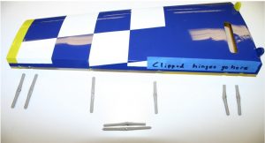 Figure 1
 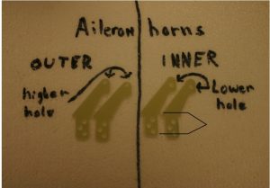 Scuff this portion onlyFigure 2
 Figure 3
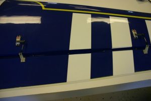 Figure 4
 Figure 5
 Figure 6
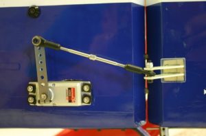 Figure 7
 Figure 8
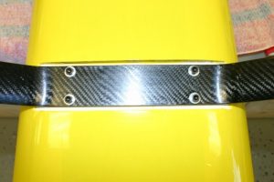 Figure 9
 Figure 10
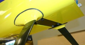 Figure 11
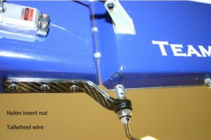 Figure 12Tailweel bracketTiller armTiller housing
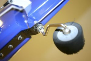 Figure 13
 Figure 14
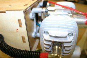 Figure 15
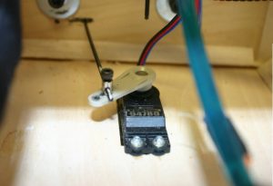 Figure 16Slot thru firewallPushrodEasy swivel connectorRound nut
 Figure 17Slot thru firewallBall linkWasherNut
 Figure 18
 Figure 19Small hole for accessto high and lowneedles oncarburetor.Typical slot cuts forstock mufflers
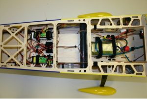 Figure 20Receiver switchIgnition switchReceiver/ignition batteriesAircraft receiverFuel tank fuel dotSecond receiver battery
Dimensions:Front of cowling to the aft most point of the rudder = 98.25”Top of canopy to ground = 26.5”Top of rudder to ground = 26”Wing span w/no SFG’s or tips = 104”Wing Span w/SFG’s and tips = 110”Outer portion of wheel pant to other wheel pant = 29.25”Horizontal stabilizer/elevator span = 41.5”Other items needed are a receiver capable or higher amp draws. When running this many servos and flying aggressively you will draw higher than normal amps thru your receiver, be sure yours is capable of this. Also we use (2) 2S 2600-3300mah lithium polymer (lipo) batteries for the servos and a 1800-2600mah lipo for the ignition on the chosen gas engine with 20-22AWG extensions.I highly recommend you secure everything within your aircraft. I use Velcro one wrap to secure all batteries, receivers, fuel tank(s) and wires. I recommend you even secure loose wiring so it will not be able to move at any time. All servo leads and extensions that will be plugged and unplugged regularly should have keepers on them or other device that will reduce the chance of them becoming unplugged, for example on your aileron extensions.Any extension(s) that will likely stay plugged in I tie themtogether with dental floss or use heat shrink to keep them together. In today’s environment high energy maneuvers are now a normal style of flying and this will increase the likelihood of faster than normal wear on items. If you fly like this, you must preflight your aircraft and perform normal inspections and maintenance.Many of our Team Extreme Flight members fly this style and do this as part of their normal routine of maintaining a safe and proper flying aircraft.
Earlier we provided a recommended setup, this is how Jeff Williams has setup his aircraft and would likely be a more popular setup for most flyers who like to run rates. However those that run only one rate might find Jase Dussia’s setup below helpful for this exact aircraft, these numbers were taken from his transmitter:Jase Dussia’s Heavy metal warbird scheme 104”MXS:Ailerons: 37.5° travel both directions/expo 40%Elevators: 65° up & down/expo 45%Rudder: left and right is as near to elevator without touching/expo 40%NOTE: be sure to use a high quality throw/angle meter to adjust your throws.Appendix A – expanded pull pull rudder explanationAssemble one end of the linkage by inserting the pull-pull cable into one of the aluminum crimp tube, through the hole in the brass rigging coupler and back through the crimp tube. Loop the cable back through the crimp tube a second time and crimp with pliers or side cutters. Also, add a small amount of Thin CA to the crimp to keep the cable from slipping when under tension.
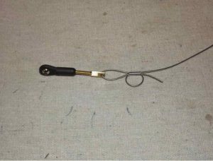 Ball linkCrimp tubeRigging coupler
Insert the bare end of the cable into the slot in the rear of the fuselage and feed it forward into the canopy area. Make the same type of linkage as done previously. Electronically center the servo and secure the linkage at both ends with a 3mm bolt and nylon insert lock nut as we did on the other surfaces.Repeat for the other side.Note: When routing the pull-pull cables through the fuse, they should cross like an “X”. Also, the tension on the wires should be taunt but not overly tightened. After your first 3-5 flights recheck the tension on the cables as they will stretch and loosen. Retighten them and then recheck them at regular intervals, we suggest checking them before every flight as part of a preflight check but don’t just forget about them.
Extreme Flight 104″ MXS-EXP ARF Assembly Manual – Extreme Flight 104″ MXS-EXP ARF Assembly Manual –
[xyz-ips snippet=”download-snippet”]