
ExtremeWireless 802.11ax AP310i/e IndoorAccess PointsAP310i/e OverviewThe AP310i/e access points are indoor model 802.11ax access points. The “i” in AP310i indicates that the access point comes with internal antennas and the “e” indicates that it comes with external antenna connectors. The access points feature built-in dual-band radios, two band-locked radios, four WiFi internal or external antennas, and one Bluetooth Low Energy (BLE) antenna.The AP310i/e can be mounted on a flat surface such as a wall, solid flat ceiling, and to a junction box or gang box, and can be installed on a suspended ceiling or a drop ceiling.
 Note: The AP310i/e requires a minimum base firmware of WiNG 7.3.1.
The AP310i/e access points have the following features:
- Radios:– Two 802.11ax radios (one 2X2 2.4GHz and 5 GHz radio, and one 2X2 5 GHz radio)– One IoT Radio (2.4 GHz)
- Console port: RJ45
- Two, 1G Ethernet ports:– GE1 port– GE2 port
- LEDs: Six– All LEDs will be on during the reset
- One reset button
- One Kensington lock
- One safety hanger provision
- One USB 2.0 type A connector
- Power: PoE 802.3at and 802.3bt (see Table 1 for details)
- Antennas:– AP310i: Four WiFi internal antennas and one BLE internal antenna– AP310e: Four RP-SMA external antenna ports and one BLE RP-SMA antenna
- Temperature:– AP310i: 0°C to +50°C (32°F to +122°F)– AP310e: -20°C to +55°C (-4°F to +131°F)
- Enclosure: Plastic
Table 1 AP310i/e Power source
| Power source | Description |
| Power over Ethernet (PoE) | Power is provided through the 1G Ethernet port ofAP310i/e, compliant to be powered with 802.3at and802.3bt to provide full functionality. For reduced functionality, use 802.3af. |
| PoE out | PoE power source is available on GE2 port when the input power is at 802.3at. |
| External 12V DC power supply(optional; ordering part #37219- PWR 12VDC, 3A, 2.5mm x 5.5mm connector) | Power is provided through an external DC power supply plugged into an AC source. |
Note PoE out is disabled when the external power supply is used.
LED Indicators
The LED indicators are located on the front face of the access point but are not visibly marked.Table 2 AP310i/e LED status
| LED indicator | LED colo | Description |
| Status | Amber | Non-operational status |
| Green | Normal operational status | |
| GE1 Ethernet | Amber | 100 Mbps |
| Green | 1000 Mbps | |
| GE2 Ethernet | Amber | 100 Mbps |
| Green | 1000 Mbps | |
| Radio 1 | Amber | 5G activity |
| Green | 2.4G activity | |
| Radio 2 | Amber | 5G activity |
| IoT (BLE) | Blue | Indicates BLE is enabled |
AP310i/e Box Contents
Ensure that the following items are available:Table 3 Contents of the AP310i/e Box
| Quantity | Item |
| 1 | AP310i/e Quick Reference |
| 2 | Access point (AP310i or AP310e) |
| 3 | Mounting bracket for 802.11ax indoor access point |
| 4 | Phillips pan head wood screws |
| 5 | Screw-in anchors |
All optional brackets and accessories are sold separately. For detailed installation instructions about all mounting procedures, refer to the ExtremeMobility Access Points AP310i/e Installation Guide in the Extreme Networks Documentation Support site.
Install the Access Point
![]() Electrical Hazard: Only qualified personnel should perform installation procedures.
Electrical Hazard: Only qualified personnel should perform installation procedures.
Use these instructions as guidelines for mounting and connecting the AP310i/e access points easily and safely.The AP310i/e comes with a Mounting Bracket (#37201) that can be used to mount the access point on a flat T-bar with flat ceiling tiles, flat surfaces, or beams. An adapter and brackets are available for mounting the access point to non-flat ceiling tiles and T-bars. To mount the AP310i/e on a junction box or a gang box, use the optional bracket (WS- MBIWALL04; #30516).Note: The mounting procedures for installing the access point using the WSMBI-DCFLUSH (ordering part #37211) adapter to a T-bar, WS-MBI-DCMTR01 (ordering part #30518) to a T-bar, and using the main mounting bracket (ordering part #37201) along with a flat metal easy-attach adapter (ordering part #37210), accessory BRKT-000147A- 1 (beam clip), and KT-135628-01 are covered in the ExtremeWireless Access Points AP310i/e Installation Guide.
Install the Access Point on a Wall or a Flat Ceiling
Pre-installation checklist:
- The mounting surface, item, and hardware must be able to support the access point in all environmental conditions.
- The mounting surface should be flat.
Option 1: Install the Access Point Using the Main Mounting Bracket
- Using the main mounting bracket as a template, mark and drill the hole centers on the wall.
 Note: The four feet of the bracket and the arrow mark must be vertical and pointing up, and the flat part of the bracket must be touching the flat surface.
 - Insert the screws into the mounting bracket holes and use the screw-in anchors if needed.
- Insert the Ethernet cable into the GE1 port.
- Insert the access point onto the bracket feet and slide it down to lock it in place.
Option 2: Install the Access Point Using an Optional Wall and Box Bracket Note: Mounting the access point to a flat ceiling requires the WS-MBI-WALL04 (#30516) bracket, two Phillips pan head wood screws, and two screw-in anchors.
- Install the WS-MBI-WALL04 bracket onto a wall or a flat ceiling with two screws and anchors if appropriate, and ensure that the locking tab is on the top side.– Use the optional wall and box bracket as a template and mark the holes to be used. For the wall mounting procedure, the best practice is to use “A” or “B” hole centers.– Mark the hole centers to be used on the attachment surface.– Drill the holes and attach the bracket using the screws and anchors provided in the kit.
- Insert the Ethernet cable into the GE1 port.
- Insert the access point onto the keyhole posts, slide the access point and lock it into place at about 1/4th inch from the wall. Install the Access Point on a Suspended or Drop Ceiling The AP310i/e can be mounted to a suspended or drop ceiling directly by using the main mounting bracket on the T-bar. If there is a ceiling tile protrusion, add the optional T-bar adapter to the main mounting bracket prior to T-bar installation.
Option 1: Install the Access Point Using the Main Mounting Bracket on a Flat T-barPre-installation checklist:
- The minimum T-bar thickness is 0.787 mm (0.031 in.)
- The maximum T-bar base thickness is 1.397 mm (0.055 in.)
Note: The T-bar width can be 24.00 mm (0.94 in.)
- Remove the ceiling tiles and then push and rotate the main mounting bracket onto the T-bar in such a way that the main bracket center angled locking tabs get attached to the T-bar (Figure 2).
- Attach the RJ45 connector of the Ethernet cable to the GE1 port.
- Hold the access point, and rock it back and forth to ensure it is securely mounted.
- Replace the ceiling tiles in place.
 Attach the RJ45 connector of the Ethernet cable to the GE1 port.
Option 2: Install the Access Point Using an Adapter on the Main Mounting BracketNote: If you are mounting the access point to a suspended or drop ceiling with a protrusion, you require an optional adapter (Universal Mounting Kit for WLAN APs; # KT- 135628-01). The adapter requires a flat T-bar and fits a ceiling tile with up to an 8.9 mm (0.35 in.) protrusion from the T-bar.
- Attach the T-bar adapter by lining up the small bends on the adapter with the long raised parts on the main bracket. Pull up the locking pin on the adapter, and twist it. After lining up the adapter, untwist the locking pin and make sure the locking pin goes into the locking pinhole on the main bracket and locks in place.
- Attach the Ethernet cable to the GE port.
- Hold the access point, and rock it back and forth to ensure that it is securely mounted.
- Slide the T-bar holder onto the T-bar, fasten the locking pin, and replace the tiles to hold the adapter onto the T-bar.The optional WS-MBI-DCMTR01 (#30518) adapter can be used for T-bar installations without the main mounting bracket.For detailed instructions, see the ExtremeWireless Access Points AP310i/e Installation Guide.

Install the Access Point on a Junction Box or Gang Box
Use the WS-MBI-WALL04 (#30516) to mount the access point on a junction box or gang box.
- Remove the screws from the box.
- Line up the bracket holes with the hole on the box.If the holes do not align, drill new holes. Note: When you line up the holes, the bracket locking tab must be pointing up and the box must be fully covered by the bracket. The two bracket holes that are being used must be on the opposite side of the large center bracket hole.Note: If the holes that you need to use are not near the corners of the bracket, break off the corner to decrease the visibility of the bracket after the access point is installed.
- Using the aligned holes, attach the bracket to the box using the screws removed from the box earlier. Caution: Overtightening the screws will cause the bracket to bend. If the bracket bends, you will not be able to slide the access point onto the keyhole posts.
- Connect the Ethernet cable to the access point.
- Align the keyhole slots and posts, and then slide the access point onto the bracket until you hear it lock in place.
Install the Access Point on a Beam
Pre-installation checklist:
- The beam must be able to support the access point in all environmental conditions.
- The beam must be flat.Before attaching the access point onto a beam, verify that:
- Beam attachment area is at least 12.7 mm (0.5 in.) wide and as long as the largest dimension of the access point.
- The beam mounting surface is less than 16.50 mm (0.65 in.) thick.
To attach an access point to a beam, attach a beam clip (BRKT-000147A-01) to the mounting bracket:
- Attach the adapter to the mounting bracket by using a twisting motion.
- Attach the mounting bracket to the access point.
- Place the adapter on a beam in such a way that there is enough space between the screw and clamp to be tightened.
- Use the screw and clamp on the top of the adapter to secure the access point in place on the beam.
- Insert the Ethernet plug into the access point.
Connect a Power Supply
If you need to power the AP310i/e access point with an external 12V DC power supply, you can plug the power cord into the power connector on the back of the access point. There is no wall mount for the 12V DC power supply. The power LED on the front face of the access point is lit when the power supply is connected. For information about optional power supplies, refer to the ExtremeWireless Access Points AP310i/e Installation Guide.
Professional Installation Instruction
Installation personnelThis product is designed for specific application and needs to be installed by qualified personnel who has RF and related rule knowledge. The general user shall not attempt toinstall or change the setting.External antennaUse only approved antennas. Non-approved antennas may produce unwanted spurious or excessive RF transmitting power which may lead to the violation of FCC/IC limit and is prohibited.Installation procedureRefer to the ExtremeWireless Access Points AP310i/e Installation Guide.![]() Warning: Select the installation position and ensure that the final output power does not exceed the limit set forth in relevant rules. The violation of the rule could lead to serious federal penalties.
Warning: Select the installation position and ensure that the final output power does not exceed the limit set forth in relevant rules. The violation of the rule could lead to serious federal penalties.
GE and Console Connections
The AP310i/e has two GE (Ethernet) ports and a Console port. During administration and maintenance through the Console, the access point must still have a power connection through either an Ethernet PoE cable or an external DC power supply.
Antenna Configurations for External Antenna Model 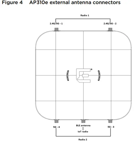 Antenna socket radio mapping information
- Radio 1 (R1) – antennas 1 and 2
- Radio 2 (R2) – antennas 3 and 4
- IoT radio – BLE antenna
Regulatory and Compliance Information
Safety Guidelines
This section contains notices that are intended to protect your personal safety and to prevent damage to the equipment.Qualified Personnel: Electrical Hazard: Only qualified personnel should perform installation procedures. Within the context of the safety notes in this documentation, qualified persons are defined as persons who are authorized to commission, ground, and label devices, systems, and circuits in accordance with established safety practices and standards. A qualified person understands the requirements and risks involved with installing outdoor electrical equipment in accordance with national codes.![]() Warning: MPE Statement – Mobile device: This equipment complies with EU radiation exposure limits set forth for an uncontrolled environment. This equipment should be installed and operated with a minimum distance of 26 cm between the radiator and your body.Federal Communications Commission (FCC) NoticeThis equipment has been tested and found to comply with the limits for a Class B digital device, pursuant to Part 15 of the FCC Rules. These limits are designed to provide reasonable protection against harmful interference in a residential installation. This equipment generates, uses, and can radiate radio frequency energy and, if not installed and used in accordance with the instructions, may cause harmful interference to radio communications. However, there is no guarantee that interference will not occur in a particular installation. If this equipment does cause harmful interference to radio or television reception, which can be determined by turning the equipment off and on, the user is encouraged to try to correct the interference by one of the following measures:
Warning: MPE Statement – Mobile device: This equipment complies with EU radiation exposure limits set forth for an uncontrolled environment. This equipment should be installed and operated with a minimum distance of 26 cm between the radiator and your body.Federal Communications Commission (FCC) NoticeThis equipment has been tested and found to comply with the limits for a Class B digital device, pursuant to Part 15 of the FCC Rules. These limits are designed to provide reasonable protection against harmful interference in a residential installation. This equipment generates, uses, and can radiate radio frequency energy and, if not installed and used in accordance with the instructions, may cause harmful interference to radio communications. However, there is no guarantee that interference will not occur in a particular installation. If this equipment does cause harmful interference to radio or television reception, which can be determined by turning the equipment off and on, the user is encouraged to try to correct the interference by one of the following measures:
- Reorient or relocate the receiving antenna.
- Increase the separation between the equipment and receiver.
- Connect the equipment into an outlet on a circuit different from that to which the receiver is connected.
- Consult the dealer or an experienced radio/TV technician for help.
![]() Caution: Any changes or modifications not expressly approved by the party responsible for compliance could void the user’s authority to operate this equipment.This device complies with Part 15 of the FCC Rules. Operation is subject to the following two conditions: (1) This device may not cause harmful interference, and (2) this device must accept any interference received, including interference that may cause undesired operation. This transmitter must not be co-located or operating in conjunction with any other antenna or transmitter.
Caution: Any changes or modifications not expressly approved by the party responsible for compliance could void the user’s authority to operate this equipment.This device complies with Part 15 of the FCC Rules. Operation is subject to the following two conditions: (1) This device may not cause harmful interference, and (2) this device must accept any interference received, including interference that may cause undesired operation. This transmitter must not be co-located or operating in conjunction with any other antenna or transmitter.![]() Warning: FCC Radiation Exposure Statement: This equipment complies with FCC radiation exposure limits set forth for an uncontrolled environment. This equipment should be installed and operated with a minimum distance of 26 cm between the radiator and your body.Industry Canada Notice This device complies with ISED’s license-exempt RSS. Operation is subject to the following two conditions: (1) This device may not cause harmful interference, and (2) this device must accept any interference received, including interference that may cause undesired operation.
Warning: FCC Radiation Exposure Statement: This equipment complies with FCC radiation exposure limits set forth for an uncontrolled environment. This equipment should be installed and operated with a minimum distance of 26 cm between the radiator and your body.Industry Canada Notice This device complies with ISED’s license-exempt RSS. Operation is subject to the following two conditions: (1) This device may not cause harmful interference, and (2) this device must accept any interference received, including interference that may cause undesired operation.![]() Warning: IC Radiation Exposure Statement: This equipment complies with ISED radiation exposure limits set forth for an uncontrolled environment. This equipment should be installed and operated with a minimum distance of 28 cm between the radiator and your body.This radio transmitter [IC: 4141B-AP310] has been approved by Innovation, Science, and Economic Development Canada to operate with the antenna types listed in ExtremeWireless Access Points AP310i/e Installation Guide, with the maximum permissible gain indicated. Antenna types not included in this list that have a gain greater than the maximum gain indicated for any type listed are strictly prohibited for use with this device.Australia Notice
Warning: IC Radiation Exposure Statement: This equipment complies with ISED radiation exposure limits set forth for an uncontrolled environment. This equipment should be installed and operated with a minimum distance of 28 cm between the radiator and your body.This radio transmitter [IC: 4141B-AP310] has been approved by Innovation, Science, and Economic Development Canada to operate with the antenna types listed in ExtremeWireless Access Points AP310i/e Installation Guide, with the maximum permissible gain indicated. Antenna types not included in this list that have a gain greater than the maximum gain indicated for any type listed are strictly prohibited for use with this device.Australia Notice![]() Warning: AU co-location MPE Statement: This equipment complies with AU radiation exposure limits set forth for an uncontrolled environment. This equipment should be installed and operated with a minimum distance of 24 cm between the radiator and your body.
Warning: AU co-location MPE Statement: This equipment complies with AU radiation exposure limits set forth for an uncontrolled environment. This equipment should be installed and operated with a minimum distance of 24 cm between the radiator and your body.
Other Countries
Brazil
Hazardous Substances
This product complies with the requirements of Directive 2011/65/EU of the European Parliament and of the Council of 8 June 2011 on the restriction of the use of certain hazardous substances in electrical and electronic equipment.
NCC Statement
CE Information
The device is restricted to indoor use only when operating in the 5150 to 5350 MHz frequency range.![]() Warning: CE co-location MPE Statement: This equipment complies with CE radiation exposure limits set forth for an uncontrolled environment. This equipment should be installed and operated with a minimum distance of 20 cm between the radiator and your body.
Warning: CE co-location MPE Statement: This equipment complies with CE radiation exposure limits set forth for an uncontrolled environment. This equipment should be installed and operated with a minimum distance of 20 cm between the radiator and your body.
All Operational Modes
AP310i and AP310e2.4GHz: 802.11b, 802.11g, 802.11n (HT20), 802.11n (HT40), 802.11ax (HEW20), 802.11ax (HEW40), 802.15.4 (Thread), Bluetooth (LE)5GHz: 802.11a, 802.11n (HT20), 802.11n (HT40), 802.11ac (VHT20), 802.11ac (VHT40), 802.11ac (VHT80), 802.11ac (VHT160), 802.11ax (HEW20), 802.11ax (HEW40), 802.11ax (HEW80), 802.11ax (HEW160)The frequency and the maximum transmitted power in the EU are listed below:2412-2472MHz: 19.98 dBm2402-2480MHz (LE): 6.23 dBm5180-5240MHz: 22.98 dBm5260-5320MHz: 22.98 dBm5500-5700MHz: 29.98 dBm2405-2480MHz: 6.48 dBm
 |
AT | BE | BG | HR | CY | CZ | DK |
| EE | Fl | FR | DE | EL | HU | IE | |
| IT | LV | LT | LU | MT | NL | PL | |
| PT | RO | SK | SI | ES | SE | UK |
European Waste Electrical and Electronic Equipment (WEEE) Notice
In accordance with Directive 2012/19/EU of the European Parliament on waste electrical and electronic equipment (WEEE):

- The symbol above indicates that a separate collection of electrical and electronic equipment is required.
- When this product has reached the end of its serviceable life, it cannot be disposed of as unsorted municipal waste. It must be collected and treated separately.
- It has been determined by the European Parliament that there are potential negative effects on the environment and human health as a result of the presence of hazardous substances in electrical and electronic equipment.
- It is the users’ responsibility to utilize the available collection system to ensure WEEE is properly treated. For information about the available collection system, please contact Extreme Environmental Compliance at [email protected].Declaration of Conformity in Languages of the European Community
Hereby, Extreme Networks, declares that the radio equipment type (AP310i/e) is in compliance with Directive 2014/53/EU. For the full text of the EU Declaration of Conformity, please contact Extreme Regulatory Compliance at [email protected]
ExtremeWireless™Indoor Access Points
Quick ReferenceAP310iAP310e
NoticeCopyright © 2020 Extreme Networks, Inc. All Rights Reserved.Legal NoticesExtreme Networks, Inc. reserves the right to make changes in specifications and other information contained in this document and its website without prior notice. The reader should in all cases consult representatives of Extreme Networks to determine whether any such changes have been made.The hardware, firmware, software or any specifications described or referred to in this document are subject to change without notice.TrademarksExtreme Networks and the Extreme Networks logo are trademarks or registered trademarks of Extreme Networks, Inc. in the United States and/or other countries.All other names (including any product names) mentioned in this document are the property of their respective owners and may be trademarks or registered trademarks of their respective companies/owners.For additional information on Extreme Networks trademarks, please see: www.extremenetworks.com/company/legal/trademarks/Documentation, Installation Videos, and SupportFor product support, including Documentation and Installation Videos, visit: www.extremenetworks.com/documentation
P/N 9036534-02 Rev AA
 report this ad
References
[xyz-ips snippet=”download-snippet”]