![]() X450-G2 Series SwitchQuick Reference
X450-G2 Series SwitchQuick Reference
 Electrical Hazard: Only qualified personnel should perform installation procedures.For complete installation instructions see the Extreme Networks Summit Family Hardware Installation Guide at: www.extremenetworks.com/documentation
Hardware Components
Figure 1 and Figure 2 display the panel ports, LEDs, and hardware components on the X450-G2 Series switches. See the Extreme Networks Summit Family Hardware Installation Guide for component details.
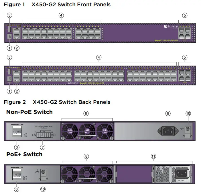
| 1 Stack LED2 Console/Management ports3 USB port4 10/100/1000BASE-T or 10/100/1000BASE-T PoE+ ports5 1000BASE-X SFP or 10G SFP+ ports6 21 Gb stacking ports (QSFP+) | 7 Redundant power supply (RPS) connector8 Front-to-back fan module slot9 AC power input connector10 Grounding screw11 PoE+ power supply bays |
Installation Site Requirements
The installation site must be within reach of the network cabling and meet the requirements listed below:
- Appropriate grounded power receptacles must be located within 6 feet of the site.
- A temperature of between 0°C (32°F) and 50°C (122°F) must be maintained at the installation site with fluctuations of less than 10°C (18°F) per hour.
- Installing the system as described in this guide meets the protective earth grounding requirements of the National Electrical Code (NEC) UL 60950 and IEC 60950 standards. If it is necessary to use an alternative grounding method, connect a 14 AWG wire between the ground screw on the chassis and a nearby building ground point.
 Caution: To ensure proper ventilation and prevent overheating, leave a minimum clearance space of 5.1 cm (2.0 in.) at the front, back, and left (power supply air intake) side of the device.Warning: A readily accessible disconnect device shall be incorporated in the building installation wiring.Avertissements: Incorporez sur le circuit de câblage un dispositif de déconnexion facilement accessible.
Handling the Switch
 Caution: The switch can be damaged by electrostatic discharge.
To prevent electrostatic damage, attach an electrostatic discharge (ESD) wrist strap to your wrist before handling the switch.Unpack the switch as follows:
- Remove the packing material protecting the switch.
- Remove the tape seal on the non-conductive bag to remove the switch.
- Perform a visual inspection of the switch for any signs of physical damage. Contact Extreme Networks if there are any signs of damage. See “Getting Help” for more information on contacting Extreme Networks.
Installing the Summit X450-G2 Series Switch
You can install a Summit X450-G2 Series switch in a rack. There are four possible rack mounting configurations, depending upon whether:
- The switch I/O ports or the power supply side of the device face front
- The device is mounted flush with the rack posts or mid-mounted
Stacking Switches
Up to eight X450-G2 Series switches can be stacked together and connected, allowing the entire stack to operate with a single IP address. You can use the following ports for stacking:
- 21Gb QSFP+ stacking ports (Figure 2, callout 6)—The stacking ports require QSFP+ direct attach passive copper cables, which are available in multiple lengths. You must order these cables separately.Note: The 21Gb QSFP+ stacking ports do not support 40Gb Ethernet optical cables.
- Front panel 10GbE SFP+ ports (Figure 1 callout 5)—If your X450-G2 Series switch has 10GbE SFP+ ports, you can use two of those ports and SummitStack-V to create a stack that includes other Summitswitch models equipped with 10GbE SFP+ ports.
For complete information about stacking, refer to the Extreme Networks Summit Family Hardware Installation Guide.
Securing the Switch to the Rack
Caution: Before rack-mounting, the device, ensures that the rack can support it without compromising stability. Otherwise, personal injury and/or equipment damage may result.
 Note: The rack mounting brackets provide two holes for securing the Summit X450-G2 Series switch to the rack. Use two screws or fasteners appropriate to your rack on each side when securing the X450-G2 Series switch to the rack.We recommend that you install the power supplies in the Summit X450-G2 Series switch after you have secured the switch to the rack to minimize the weight that must be supported when installing rack screws.
To secure the Summit X450-G2 Series switch to the rack:
- Attach the mounting brackets to the sides of the switch using six screws for each bracket.
- Align the rack mount earholes with the front rack post holes.
- Secure the Summit X450-G2 Series switches to each rack post with at least two screws or fasteners appropriate to the rack.Note: If using one power supply, you can install it in either of the two power supply bays. Insert a blank cover, provided with the switch, on the unused power supply bay.
Installing Pluggable Transceivers
 Warning: Fiber-optic SFP and SFP+ ports use Class 1 or Class 1M lasers.LASER RADIATIONDO NOT EXPOSE USERS OF TELESCOPIC OPTICSCLASS 1 OR 1M LASER PRODUCTDo not use optical instruments to view the laser output. The use of optical instruments to view laser output increases eye hazard. Use only UL/CSA recognized pluggable modules.To install a transceiver in a Summit X450-G2 Series switch:
- Attach the anti-static wrist strap. Refer to the instructions on the anti-static wrist strap package.
- Carefully align the transceiver with the port slot and push the transceiver into the port slot until the transceiver clicks and locks into place.
Installing the Fan Tray
Caution: You must install the front-to-back fan tray (Part # 10945) before connecting power to the switch.Note: The X450-G2 Series switch does not ship with the fan tray. You must purchase the front-to-back fan tray separately.To install the front-to-back fan tray in a Summit X450-G2 Series switch:
- Carefully slide the fan tray module into the switch (see Figure 2, callout 8).
- Align and fully tighten the captive retaining screws with a 1/4-inch flat-blade screwdriver.
Connecting Power to the SwitchPoE+ SwitchesWarning: Extreme Networks’ power supplies do not have switches for turning the unit on and off. Disconnect all power cords to remove power from the device. Make sure that these connections are easily accessible.Warning: A dedicated Listed circuit breaker rated at 15A is to be used for each power supply connection.Note: The PoE+ Summit X450-G2 Series switches do not ship with any power supplies. You must purchase the front-to-back power supplies (715W or 1100W) separately. See Table 2.
After you have installed the power supply modules, you can connect to a single, primary source of power, or to two sources of power for redundancy.To power up your X450-G2 Series switch:
- Attach power cords to the modular PoE+ power supplies installed in the X450-G2 Series switch.
- Once power is connected, verify that the PSU LED (P1 and/or P2) turns green. If the PSU LED does not turn green, refer to the Extreme Networks Summit Family Hardware Installation Guide for troubleshooting information.
Non-PoE SwitchesYou can connect to a single, primary source of power, or to two sources of power for redundancy. The example used here describes connecting to two power sources.To power up your X450-G2 Series switch:
- If applicable, attach the power cord from your redundant power supply into the X450-G2 Series switch’s redundant power receptacle.
- Attach the AC power cord to the X450-G2 Series switch’s AC power receptacle.
- Plug the redundant power supply and the X450-G2 Series switch AC power cords into dedicated, grounded AC outlets.
- Once power is connected, verify that the CPU (system) LED turns amber until the X450-G2 Series switch finishes its initialization.If the initialization process is successful, the CPU LED turns green. If the CPU LED does not turn green, refer to the Extreme Networks Summit Family Hardware Installation Guide for troubleshooting information.
Purchasing Power Cords
The X450-G2 switches do not include AC power input cords. To purchase the correct power cord for your location, refer to www.extremenetworks.com/product/powercords/.
Initial Network Connection and Configuration
Once you have connected power to the switch and verified LED activity, complete the setup process as follows:
- Connect a management station to the console port using either an Ethernet to serial adapter or DB-9 serial cable.
- Verify that the system LEDs are on (solid green or blinking green).
- Using PuTTY, TeraTerm, or another terminal emulator, connect to the switch using the serial port connection. Be sure that your serial connection is set properly:– 9600 baud– 8 data bits– 1 stop bit
- Using the console session, perform the following:a At the password prompt, press ENTER (RETURN) twice.b Enter user: adminc For the initial password, simply press ENTER.d Follow the screen prompts for initial configuration.e Enter the show version command. Record the switch serial number. The following is an example output with the serial number in bold:Transit.3 # show versionSwitch : 800444-00-05 0723G-01234 Rev 5.0 BootROM:
- Go to Extreme Networks Support Portal at: https://support.extremenetworks.com
- After logging in, go to the product registration page.
- Enter the serial number of the switch.
- Download the software to your PC from the software download page.
- Connect back to the switch via the console port and connect an Ethernet cable to the management port on the switch to your PC.• You might need to reset the IP address on your PC to some address (for example, 10.10.10.10 255.255.255.0) to avoid IP conflict.
- At the switch, set the IP address of the switch (for example, enter: con mgmt Sipa 10.10.10.9/24).
- Enter save config to save your configuration.
- Start a TFTP session using a program such as TFTPD64. Point the TFTP server to your PC IP address and the ExtremeXOS image file saved on your PC.
- At the switch, download the new software to the switch (example: download image 10.10.10.10 summits-in.n.n.n-patch1-in.xos).
- Select Y when asked whether you want to install the downloaded software.
- When the download and install finishes, instruct the switch to reboot when prompted by entering: reboot.
Optional CLI Commands
Once logged into the switch you can create new VLANs by issuing the following two commands:
- create vlan <vlan name>
- configure vlan <vlan name> tag XXXXReplace XXXX with the VLAN tag number (1–4096)
These two commands will create a VLAN, give it a logical name, and assign a tag number.To configure a Default Gateway in the Extreme Networks CLI enter: configure iproute add default <IP address>
Port Configuration CLI Commands
For additional port configuration CLI commands, refer to the ExtremeXOS Command Reference Guide at: www.extremenetworks.com/documentation.
Specifications
Temperature and HumidityOperating: 0°C to 50°C (32°F to 122°F)Storage: -40°C to 70°C (-40°F to 158°F)Operating relative humidity: 10% to 95% (non-condensing)
Switch Dimensions
4.40 cm (1.73”) Height x 44.1 cm (17.4”) Width x 48.7 cm (19.2”) Depth
Interfaces
Each X450-G2 Series switch has a USB, console, and management port. The following table lists the specific data interfaces for each model.Table 1 X450-G2 Series Interface Descriptions
| X450-G2-24t-GE4 (Part # 16172) | .24 10/100/1000BASE-T. 4 100013ASE-X unpopulated SFP, two 21Gb stacking ports (QSFP+) |
| X450-G2-24t-lOGE4 (Part # 16176) | 24 10/100/1000BASE-T, 4 10GBASE-X unpopulated SFP+, two 21Gb stacking ports (QSFP+) |
| X450-G2-48t-GE4 (Part # 16174) | 48 10/100/1000BASE-T, 4 1000BASE-X unpopulated SFP, two 21Gb stacking ports (QSFP+) |
| X450-G2-48t-lOGE4 (Part # 16178) | 48 10/100/1000BASE-T, 4 10GBASE-X unpopulated SFP+, two 21Gb stacking ports (QSFP+) |
| X450-G2-24p-GE4 (Part # 16173) | 24 10/100/1000BASE-T POE+, 4 1000BASE-X unpopulated SFP, two 21Gb stacking ports (QSFP+) |
| X450-G2-24p-10GE4 (Part # 16177) | 24 10/100/1000BASE-T POE+, 4 10GBASE-X unpopulated SFP+, two 21Gb stacking ports (QSFP+) |
| 450-G2-48p-GE4rPart# 16175) r450-G2-48p-10GE4 | 48 10/100/1000BASE-T POE+, 4 1000BASE-X unpopulated SFP, two 21Gb stacking ports (QSFP+) |
| Part # 16179) | 48 10/100/1000BASE-T POE+, 4 10GBASE-X unpopulated SFP+, two 21Gb stacking ports (QSFP+) |
Power Supplies
Table 2 X450-G2 Series Power Supply Specifications
| X450-G2 Series Model I | Power Supply |
| Fixed power supply with front-to-back airflow | |
| X450-G2-24t-GE4 (Part # 16172) X450-G2-24t-lOGE4 (Part # 16176) | 100-240V-. 50/60 Hz. 1.0 A |
| X450-G2-48t-GE4 (Part # 16174) X450-G2-48t-1OGE4 (Part # 16178) | 100-240V-. 50/60 Hz. 1.0 A |
| Modular power supply with front-to-back airflow | |
| X450-G2-24p-GE4 (Part # 16173) X450-G2-24p-IOGE4 (Part # 16177) | • 1100W AC PS FB (front to back) Part #: 10941, Model: PSSF112101A 100-127V/200-240V-, 50-60 Hz, 10.0 A/5.0 A max per PS715W AC PS FB (front to back) Part #: 10951, Model: PSSF711101A 100-127V/200-240V-, 50-60 Hz, 7.0 A/3.5 A max per PS |
| X450-G2-48p-GE4 (Part # 16175) X450-G2-48p-1OGE4 (Part # 16179) | 1100W AC PS FB (front to back) Part #: 10941, Model: PSSF112101A 100-127V/200-240V-, 50-60 Hz, 12.0 A/6.0 A max per PS715W AC PS FB (front to back) Part #: 10951, Model: PSSF711101A 100-127V/200-240V-, 50-60 Hz. 8.0 A/4.0 A max per PS |
Note: X450-G2 Series switches do not support back-to-front power supplies.
External Redundant Power Supply Options
The following redundant power supplies are available for purchase from Extreme Networks for connection to the non-PoE Summit X450-G2 Series switches:
- The AC redundant power supply (Part # 10929, Model: TG11-0156-01), which is capable of providing power to a fully-loaded non-PoE switch.
- The EPS-C2 redundant power supply chassis (Part # 10936), to which you can install up to three Summit 750W AC power supplies (Part # 10931). You must use the EPS-CBL-2×7 cable (Part # 10939) to connect the power supply to the switch.
Note: The PoE+ Summit X450-G2 Series switches have dual hot-swappable power supplies for power redundancy.
Getting Help
For additional support related to Summit X450-G2 Series switches or this document, contact Extreme Networks using one of the following methods:
| World Wide Web | http://support.extremenetworks.com/ |
| Phone | 1-800-872-8440 (toll-free in U.S. and Canada) or 1-603-952-5000For the Extreme Networks Support toll-free number in your country:www.extremenetworks.com/support/contact/ |
| The latest image and release notes | http://support.extremenetworks.com/ |
NoticeCopyright © 2014 Extreme Networks, Inc. All Rights Reserved.Legal NoticesExtreme Networks, Inc., on behalf of or through its wholly-owned subsidiary, Enterasys Networks, Inc., reserves the right to make changes in specifications and other information contained in this document and its website without prior notice. The reader should in all cases consult representatives of Extreme Networks to determine whether any such changes have been made.The hardware, firmware, software or any specifications described or referred to in this document are subject to change without notice.TrademarksExtreme Networks and the Extreme Networks logo are trademarks or registered trademarks of Extreme Networks, Inc. in the United States and/or other countries.All other names (including any product names) mentioned in this document are the property of their respective owners and may be trademarks or registered trademarks of their respective companies/owners.For additional information on Extreme Networks trademarks, please see: www.extremenetworks.com/company/legal/trademarks/WarrantyWarranty information for X450-G2 series switches is located online at: www.extremenetworks.com/go/warrantySupportFor product support, including documentation, visit: http://support.extremenetworks.com/ContactExtreme Networks, Inc.145 Rio RoblesSan Jose, CA 95134Tel: +1 408-579-2800Toll-free: +1 888-257-3000
Regulatory and Compliance Information
Federal Communications Commission (FCC) NoticeThis device complies with Part 15 of the FCC rules. Operation is subject to the following two conditions: (1) this device may not cause harmful interference, and (2) this device must accept any interference received, including interference that may cause undesired operation.NOTE: This equipment has been tested and found to comply with the limits for a class A digital device, pursuant to Part 15 of the FCC rules. These limitsare designed to provide reasonable protection against harmful interference when the equipment is operated in a commercial environment. This equipment uses, generates, and can radiate radio frequency energy and if not installed in accordance with the operator’s manual, may cause harmful interference to radio communications. Operation of this equipment in a residential area is likely to cause interference in which case the user will be required to correct the interference at his own expense.WARNING: Changes or modifications made to this device that are not expressly approved by the party responsible for compliance could void the user’s authority to operate the equipment.Industry Canada NoticeThis digital apparatus does not exceed the Class A limits for radio noise emissions from digital apparatus set out in the Radio Interference Regulations of the Canadian Department of Communications.Class A ITE NoticeWARNING: This is a Class A product. In a domestic environment, this product may cause radio interference in which case the user may be required to take adequate measures.Product SafetyThis product complies with the following: UL 60950-1, FDA 21 CFR 1040.10 and 1040.11, CAN/CSA-C22.2 No. 60950-1, EN 60950-1, EN 60825-1, EN 60825-2, IEC 60950-1, 2006/95/EC.Electromagnetic Compatibility (EMC)This product complies with the following: FCC 47 CFR Part 15 (Class A), CES-003 (Class A), EN 55022 (Class A), EN 55024, EN 61000-3-2, EN 61000-3-3, AS/NZS CISPR 22 (Class A), VCCI V-3, 2004/108/EC (EMC Directive)VCCI NoticeThis is a class A product based on the standard of the Voluntary Control Council for Interference by Information Technology Equipment (VCCI). If this equipment is used in a domestic environment, radio disturbance may arise. When such trouble occurs, the user may be required to take corrective actions.BSMI EMC Statement — TaiwanThis is a class A product. In a domestic environment, this product may cause radio interference in which case the user may be required to take adequate measures.
Battery Warning — Taiwan
Battery NoticeWarning: This product contains a battery used to maintain product information. If the battery should need replacement it must be replaced by Service Personnel. Please contact Technical Support for assistance.Risk of explosion if the battery is replaced by an incorrect type. Dispose of the expended battery in accordance with local disposal regulations.
SUPPLEMENT TO PRODUCT INSTRUCTIONS
| Parts | Hazardous Substance | |||||
| PB | Hg | Cd | Cr6+ | PBB | PBDE | |
| Metal Parts | × | Ο | Ο | Ο | Ο | Ο |
| Circuit Modules | × | Ο | Ο | Ο | Ο | |
| Cables & Cable Assemblies | Ο | Ο | Ο | Ο | Ο | Ο |
| PowerAdapter/PowerSupply | × | Ο | Ο | Ο | Ο | Ο |
Ο: Indicates that the concentration of the hazardous substance in all homogeneous materials in the parts is below the relevant threshold of the SJ/T 11363-2006 standard.×: Indicates that the concentration of the hazardous substance of at least one of all homogeneous materials in the parts is above the relevant threshold of the SJ/T 11363-2006 standard.This table shows where these substances may be found in the supply chain of Extreme electronic information products, as of the date of sale of the enclosed product. Note that some of the component types listed above may or may not be a part of the enclosed product. The Environmentally Friendly Use Period (EFUP) for all enclosed products and their parts are per the symbol shown here unless otherwise marked. Certain parts may have a different EFUP (for example, battery modules) and so are marked to reflect such. The Environmentally Friendly Use Period is valid only when the product is operated under the conditions defined in the product manual.
Hazardous SubstancesThis product complies with the requirements of Directive 2011/65/EU of the European Parliament and of the Council of 8 June 2011 on the restriction ofthe use of certain hazardous substances in electrical and electronic equipment.European Waste Electrical and Electronic Equipment (WEEE) Notice
In accordance with Directive 2012/19/EU of the European Parliament on waste electrical and electronic equipment (WEEE):
- The symbol above indicates that a separate collection of electrical and electronic equipment is required.
- When this product has reached the end of its serviceable life, it cannot be disposed of as unsorted municipal waste. It must be collected and treated separately.
- It has been determined by the European Parliament that there are potential negative effects on the environment and human health as a result of the presence of hazardous substances in electrical and electronic equipment.
- It is the users’ responsibility to utilize the available collection system to ensure WEEE is properly treated.For information about the available collection system, please contact Extreme Customer Support at +353 61 705500 (Ireland).
SafetyCompliant with IEC 60950-1:2005 (Second Edition); Am1:2009 + Am2:2013, EN 60950-1:2006 + A1:2010 + A11:2009 + A12:2011 + A2:2013, UL 62950-1, 2nd Ed. 2011, CSA C22.2 No. 60950-1-07, 2nd Ed. 2011
Extreme NetworksSummit X450-G2Series SwitchesQuick ReferenceSummit X450-G2-24t-GE4Summit X450-G2-24t-10GE4Summit X450-G2-48t-GE4Summit X450-G2-48t-10GE4Summit X450-G2-24p-GE4Summit X450-G2-24p-10GE4Summit X450-G2-48p-GE4Summit X450-G2-48p-10GE4
P/N 121110-00
 report this ad
![]()
References
[xyz-ips snippet=”download-snippet”]