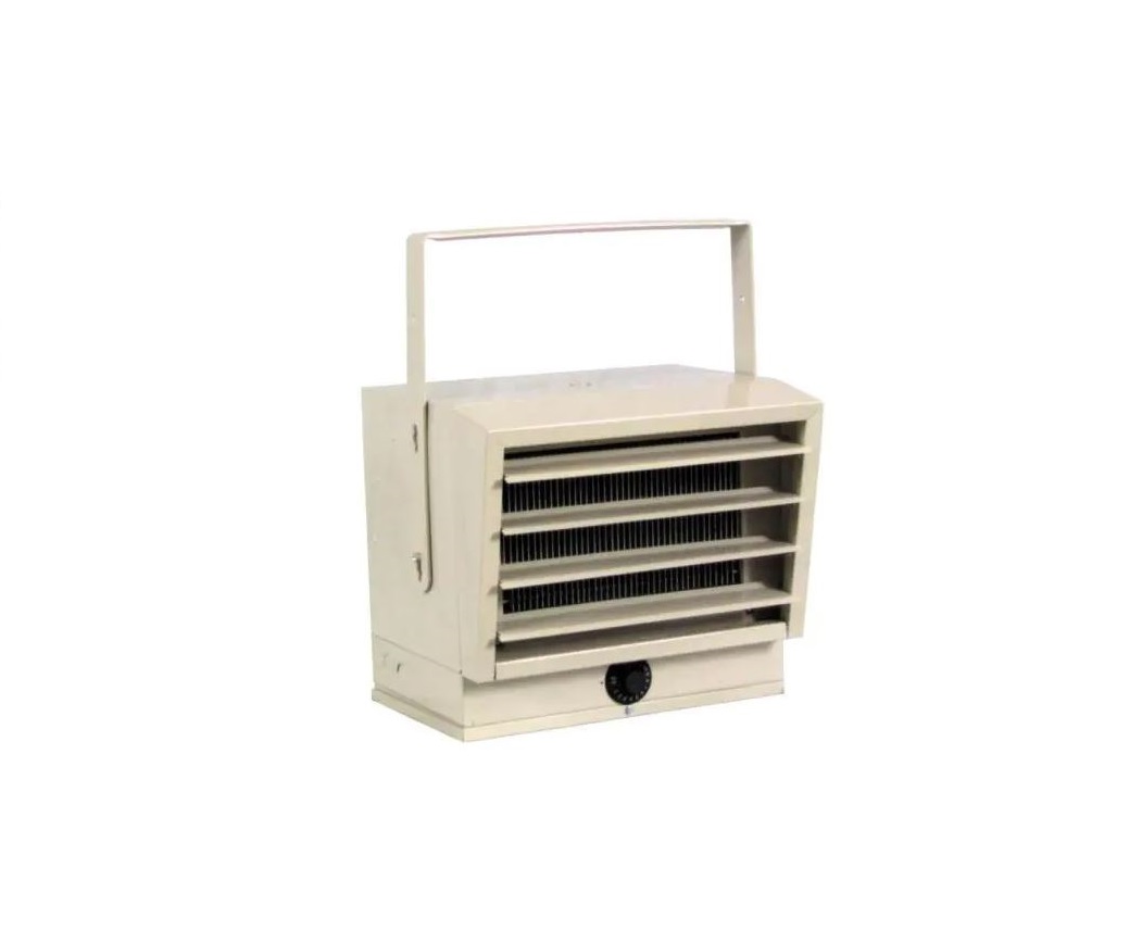
Fahrenheat FUH Series Unit Heater
Specifications FUH 54C
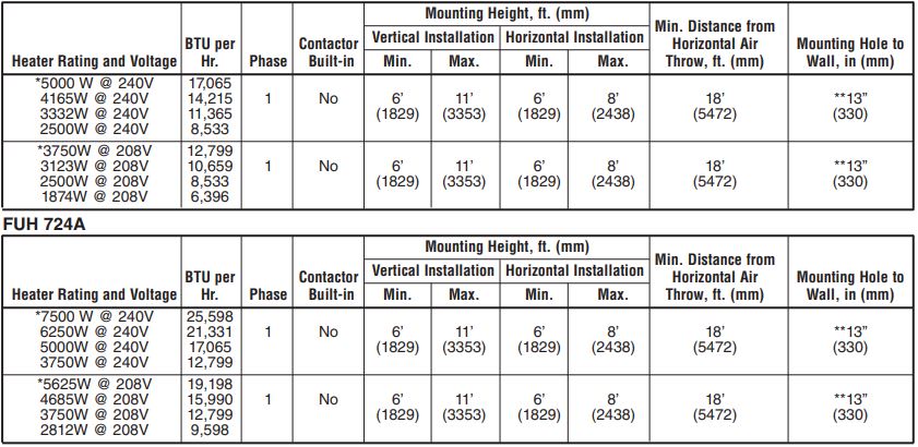
*Heater is shipped from the factory wired for these wattages. The heater can be field adjusted to the other wattages (Refer to Table 2 “Adjusting the Heat Output”.)**48″ (1219 mm) when heater airflow is between 45° downward and vertical.
IMPORTANT INSTRUCTIONS
![]() WARNING
WARNING![]()
WHEN USING ELECTRIC APPLIANCES, BASIC PRECAUTIONS SHOULD ALWAYS BE FOLLOWED TO REDUCE THE RISK OF FIRE, ELECTRIC SHOCK, AND INJURY TO PERSONS, INCLUDING THE FOLLOWING:
- Read all instructions before installing or using this heater.
- This heater is hot when in use. To avoid burns, do not let bare skin touch hot surfaces. Keep combustible materials, such as furniture, pillows, bedding, papers, clothes, etc., and curtains at least 3 feet (0.9 m) from the front of the heater.
- Extreme caution is necessary when any heater is used by or near children or invalids and whenever the heater is left operating and unattended.
- Do not operate any heater after it malfunctions. Disconnect power at service panel and have heater inspected by a reputable electrician before using.
- Do not use outdoors.
- To disconnect the heater, turn controls off, and turn off power to the heater circuit at the main disconnect panel.
- Do not insert or allow foreign objects to enter any ventilation or exhaust opening as this may cause an electric shock, fire, or damage to the heater.
- To prevent a possible fire, do not block air intake or exhaust in any manner.
- A heater has hot and arcing or sparking parts inside. Do not use it in areas where gasoline, paint, or flammable liquids are used or stored.
- Use this heater only as described in this manual. Any other use not recommended by the manufacturer may cause fire, electric shock, or injury to persons.
- This heater is provided with a red alarm light that will illuminate only if the heater has turned off as a result of overheating. If you see the light on, immediately turn the heater off and inspect for any objects on or adjacent to the heater that may have blocked the airflow or otherwise caused high temperatures to have occurred. DO NOT OPERATE THE HEATER WITH THE ALARM LIGHT ILLUMINATING.
- This heater is intended for comfort heating applications and not intended for use in special environments. Do not use in damp or wet locations such as marine or greenhouse or in areas where corrosive or chemical agents are present.
- When installing, see INSTALLATION INSTRUCTIONS for additional warnings and precautions.
- For safe and efficient operation, and to extend the life of your heater, keep your heater clean – See MAINTENANCE INSTRUCTIONS.
SAVE THESE INSTRUCTIONS
INSTALLATION INSTRUCTIONS
![]() WARNING
WARNING![]()
To prevent a possible fire, injury to persons, or damage to the heater, adhere to the following:
- Disconnect all power coming to the heater at the main service panel before wiring or servicing.
- All wiring procedures and connections must be in accordance with the National and Local Codes having jurisdiction and the heater must be grounded.
- Verify the power supply voltage coming to the heater matches the ratings as shown on the heater nameplate.CAUTION: ENERGIZING THE HEATER AT A VOLTAGE GREATER THAN THE VOLTAGE PRINTED ON THE NAMEPLATE WILL DAMAGE THE HEATER AND VOID THE WARRANTY AND COULD CAUSE A FIRE.
- CAUTION – High temperature, risk of fire, keep electrical cords, drapery, furnishings, and other combustibles at least 3 feet (0.9 m) from the front of the heater. Do not install a heater behind doors, below towel racks, or in an area where it is subject to being blocked by furniture, curtains or storage materials. Hot air from the heater may damage certain fabrics and plastics.
- To reduce the risk of fire, do not store or use gasoline or other flammable vapors and liquids in the vicinity of the heater.
- When the heater is to be wall or ceiling mounted, the anchoring provisions must be of sufficient strength to support the total weight of the heater plus the weight of the mounting provisions. Failure to properly secure the supporting members of the building structure could allow the heater to fall.
- The following minimum clearances must be maintained:For Vertical Airflow, Bottom of Heater to Floor: 6′ (1829 mm) minimum, 11′(3353 mm) maximumHorizontal Airflow, Bottom of Heater to Floor: 6′ (1829 mm) minimum, 8′(2438 mm) maximumSides of heater to an adjacent wall: Airflow from Horizontal to 45° downward: 13″ (330 mm) Airflow from 45° downward to straight down 48″ (1219 mm).Discharge to any object: 36″ (915 mm) minimum
- Do not use this heater to dry out as the paint, plaster, sawdust, and drywall sanding dust will permanently damage the heater and must be kept out of the heater.

Unpacking Your New HeaterRemove the heater from the box and inspect it for any damage. If it appears to be damaged, immediately return it to the store from which you purchased it.
Tools NeededYou will need the following tools to install your FUH Series electric heater:
- Screwdriver
- Needle nose pliers
- Pliers
- Electric Drill and 1/4″ (6.35 mm) bit
- adjustable wrench
Hardware Needed
You will also need the following hardware for installation:
- Enough 10 ga. min. insulated copper conductor (with ground) wire to run power from the breaker/ fuse to the heater. Only use copper wire rated at least 75° C. Do not use aluminum wire with this unit.
- Proper size fuses and circuit breakers in accordance with the National Electrical Code. Also, see Table 2 Heat Output Adjustments
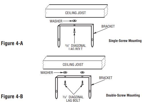
- Screw wood, 3/8″ x 2″ (9.5 mm x 50 mm) Lag bolts (Qty. 1 or 2).
- Washer, 3/8″ (9.7 mm) (Qty. 2)
- Wire connectors sized to your application.
NOTE: For certain applications, the conduit may be required (see Figure 2). Check local electrical codes. If wiring is run in a conduit, be sure there is enough flexible conduit to allow the heater to be turned if necessary.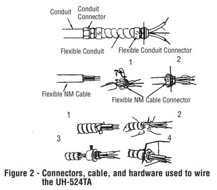
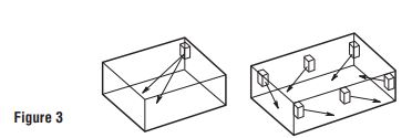
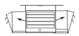
Locating the HeaterThe heater should be installed out of traffic areas and at least 6′ off the floor. The direction of airflow should not be restricted (ie: by columns or machinery) and the airflow should wipe exposed walls, rather than blowing directly at them. When more than one heater is used in an area, the heaters should be arranged so that the air discharge of each heater supports the airflow of the others to provide the best circulation of warm air, as indicated in Figure 3, below.
Mounting
- Remove the mounting bracket from the heating unit by loosening the bracket screws with a wrench and slipping the handle off over the screw heads.
- Locate a stud in the ceiling and attach the mounting bracket to the ceiling joist as shown in Figures 4-A or 4-B. Place a washer on the screw between the bracket and the ceiling to act as a spacer and screw them into the stud. Tighten the screws enough to securely hold the heating unit with the airflow pointed in the proper direction.

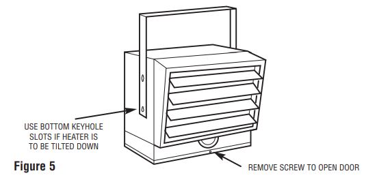
- Lift the heater up and into the mounting bracket. Align the screws on each side of the heater with the keyhole slots in the mounting brackets. If the heater is to be tilted, it must be positioned in the lower keyhole slots (see Figure 5). Tighten the bracket screws so the unit is securely suspended at the desired position.
Wiring
- To connect the power to the heater, simply remove the screw from the front of the unit. This allows the hinged bottom to open, providing access to the electrical wiring and connectors. (See Figure 5)
- Attach the cable connectors to the unit (See Figure 2) and slide the 10 gauge wire through the cable connector. Pull enough wire through the connector to work with when making the connections.NOTE: Wiring compartment volume: 370 in3 (6063 cm3)
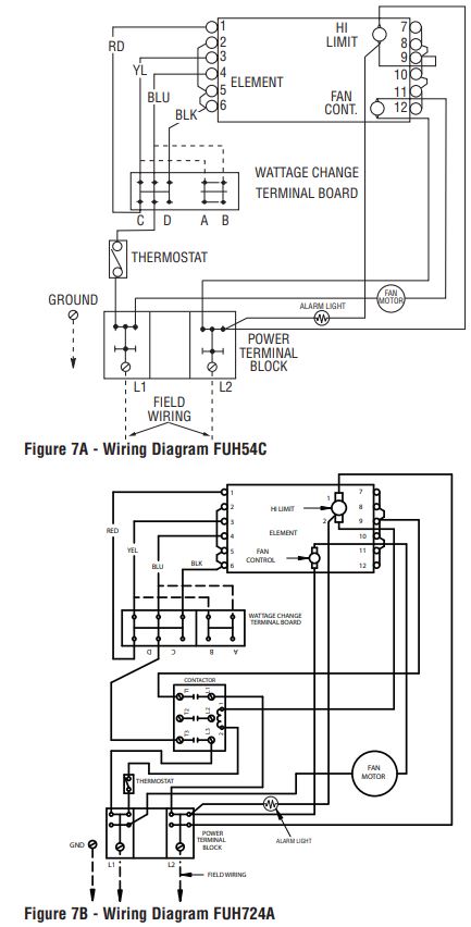
- Connect the wire to the power terminal block located at the base of the heater (See Figure 6).NOTE: Unit is 240/208 volts. When wiring a two-conductor cable with the ground the white wire must be marked black by adding a piece of black electrical tape to the wire near the point of connection.NOTE: To decrease the heat output of the heating unit, see Adjust the Heat Output, Table 2, and Wiring Diagrams

*NOTE: 240/208 volts. When wiring with a two-conductor cable with the ground, the white wire must be marked black.
![]() WARNING
WARNING![]() TO PREVENT POSSIBLE ELECTRIC SHOCK, DISCONNECT POWER TO THE HEATER AT THE MAIN SERVICE BOX BEFORE ATTEMPTING TO ADJUST THE HEAT OUTPUT OF THIS UNIT.
TO PREVENT POSSIBLE ELECTRIC SHOCK, DISCONNECT POWER TO THE HEATER AT THE MAIN SERVICE BOX BEFORE ATTEMPTING TO ADJUST THE HEAT OUTPUT OF THIS UNIT.
Adjusting the Heat OutputHeat output can be increased or decreased by switching wires at the wattage change terminal board. The heater is factory wired to deliver a heat output of 17,065 BTU per hour. Should your particular application require less heat output, refer to Table 2 below and change the wires at the wattage change terminal board as shown in Wiring Diagram Figure 7A or 7B.

OPERATING INSTRUCTIONS
- The heater must be properly installed before operation.
- After the heater is completely assembled, rotate the thermostat knob counterclockwise until the control stops. This is the minimum heat setting.
- Turn power supply to heater “ON” at the main switch panel.
- The heater should not operate. If it operates disconnect power and rechecks wiring.
- Rotate the thermostat clockwise until it stops (maximum heat setting).
- The heater should turn on after a brief delay (see Automatic Fan Delay below). If the heater and fan do not come on, disconnect power and check the wiring.NOTE: The first time you operate the unit, it may smoke slightly. This is due to the residual cleaning agents used to clean the element when the heater is manufactured. This is normal and does not indicate a problem with the unit. This condition will stop after the heater has been in operation for a few minutes.
- Allow the heater to continue to operate until the room temperature reaches desired comfort level. Then rotate the thermostat knob counterclockwise slowly until the thermostat clicks off. (Note that the fan delay will keep the fan running until the elements cool.) The heater will cycle on and off to maintain room temperature.
- It may be necessary to readjust the thermostat for a time or so until an exact comfort level is attained. Rotation in the clockwise direction will increase the amount of time the heater will produce heat. Rotation in the counterclockwise direction will reduce the amount of time the heater is on.
Automatic Fan Delay: The FUH Series has an automatic fan delay. When the thermostat calls for heat, fan action is delayed momentarily until the heating elements warm. This prevents the circulation of cold air. When the heater raises the temperature of the room to the thermostat set point, the heating element is turned off but the fan will continue to run until the heating element cools down. This prevents exposing the unit to residual heat, provides a higher comfort level and prolonged element life.
Automatic Thermal Limit: FUH Series is equipped with a thermal limit that will automatically shut off the heater in the event of overheating. Should the thermal limit activate an alarm light will be visible on the front of the heater next to the thermostat knob. The heater will turn on when the operating temperature returns to normal. Should the unit overheat and activate the thermal limit, the cause of the overheating should be determined before further operation.
![]() WARNING
WARNING![]() DO NOT TAMPER WITH OR BYPASS ANY SAFETY LIMITS INSIDE THE HEATER.
DO NOT TAMPER WITH OR BYPASS ANY SAFETY LIMITS INSIDE THE HEATER.
CAUTION![]() CAUTION- DO NOT CONTINUE TO ATTEMPT TO USE THE HEATER IF THE THERMAL LIMIT REPEATEDLY OPERATES. TO DO SO COULD PERMANENTLY DAMAGE THE HEATER OR CREATE A FIRE OR SAFETY HAZARD.
CAUTION- DO NOT CONTINUE TO ATTEMPT TO USE THE HEATER IF THE THERMAL LIMIT REPEATEDLY OPERATES. TO DO SO COULD PERMANENTLY DAMAGE THE HEATER OR CREATE A FIRE OR SAFETY HAZARD.
NOTE: If the unit is installed in an area where the temperature is below 50° F, the fan may cycle on and off until the temperature in the room rises above 50° F, this is normal and does not indicate a problem with the unit. As soon as the heater warms the air in the room above 50°, the fan will operate continuously until the thermostat has reached the room setpoint.Adjusting Air Flow DirectionYou can adjust the direction of airflow by
- Turning the unit. If the unit has been installed with a single lag bolt, as shown in Figure 8, simply turn the entire unit as needed to adjust airflow.
- Tilting the unit. Loosen the bracket screws, tilt the heater to the desired position, and re-tighten the bracket screws (see Figure 4).NOTE: To tilt the heater it must be mounted in the bottom keyhole slots of the mounting bracket to maintain adequate clearance and prevent possible overheating.
- Adjusting the louvers to the desired position.NOTE: The louvers are designed so they can not be completely closed. Do not attempt to defeat this feature, damage to the unit can result.It is important to keep this heater clean. Your heater will give you years of service and comfort with only minimum care. To assure efficient operation follow the simple instructions below.
![]() WARNING
WARNING![]() ALL SERVICING BEYOND SIMPLE CLEANING THAT REQUIRES DISASSEMBLY SHOULD BE PERFORMED BY QUALIFIED SERVICE PERSONNEL.
ALL SERVICING BEYOND SIMPLE CLEANING THAT REQUIRES DISASSEMBLY SHOULD BE PERFORMED BY QUALIFIED SERVICE PERSONNEL.
![]() WARNING
WARNING![]() TO REDUCE THE RISK OF FIRE AND ELECTRIC SHOCK OR INJURY, DISCONNECT ALL POWER COMING TO THE HEATER AT THE MAIN SERVICE PANEL AND CHECK THAT THE ELEMENT IS COOL BEFORE SERVICING OR PERFORMING MAINTENANCE.
TO REDUCE THE RISK OF FIRE AND ELECTRIC SHOCK OR INJURY, DISCONNECT ALL POWER COMING TO THE HEATER AT THE MAIN SERVICE PANEL AND CHECK THAT THE ELEMENT IS COOL BEFORE SERVICING OR PERFORMING MAINTENANCE.
User Cleaning Instructions:
- After the heater has cooled, a vacuum cleaner with brush attachment may be used to remove dust and lint from exterior surfaces of the heater including the grille openings.
- With a damp cloth, wipe dust and lint from grille and exterior surfaces.
- Return power to the heater and check to make sure it is operating properly.
Maintenance Cleaning Instructions:(To be performed only by Qualified Service Personnel)At least annually, the heater should be cleaned and serviced by a qualified service person to assure safe and efficient operation. After completing the cleaning and servicing, the heater should be checked for proper operation.
MAINTENANCE INSTRUCTIONS
It is important to keep this heater clean. Your heater will give you years of service and comfort with only minimum care. To assure efficient operation follow the simple instructions below.
![]() WARNING
WARNING![]() ALL SERVICING BEYOND SIMPLE CLEANING THAT REQUIRES DISASSEMBLY SHOULD BE PERFORMED BY QUALIFIED SERVICE PERSONNEL.
ALL SERVICING BEYOND SIMPLE CLEANING THAT REQUIRES DISASSEMBLY SHOULD BE PERFORMED BY QUALIFIED SERVICE PERSONNEL.
![]() WARNING
WARNING![]() ALL SERVICING BEYOND SIMPLE CLEANING THAT REQUIRES DISASSEMBLY SHOULD BE PERFORMED BY QUALIFIED SERVICE PERSONNEL.
ALL SERVICING BEYOND SIMPLE CLEANING THAT REQUIRES DISASSEMBLY SHOULD BE PERFORMED BY QUALIFIED SERVICE PERSONNEL.
TO REDUCE THE RISK OF FIRE AND ELECTRIC SHOCK OR INJURY, DISCONNECT ALL POWER COMING TO THE HEATER AT THE MAIN SERVICE PANEL AND CHECK THAT THE ELEMENT IS COOL BEFORE SERVICING OR PERFORMING MAINTENANCE.
User Cleaning Instructions:
- After the heater has cooled, a vacuum cleaner with brush attachment may be used to remove dust and lint from exterior surfaces of the heater including the grille openings.
- With a damp cloth, wipe dust and lint from grille and exterior surfaces.
- Return power to the heater and check to make sure it is operating properly.
Maintenance Cleaning Instructions:(To be performed only by Qualified Service Personnel)At least annually, the heater should be cleaned and serviced by a qualified service person to assure safe and efficient operation. After completing the cleaning and servicing, the heater should be checked for proper operation.
LIMITED WARRANTYAll products manufactured by Marley Engineered Products are warranted against defects in workmanship and materials for one year from the date of installation, except heating elements which are warranted against defects in workmanship and materials for five years from the date of installation. This warranty does not apply to damage from an accident, misuse, or alteration; nor where the connected voltage is more than 5% above the nameplate voltage; nor to equipment improperly installed or wired or maintained in violation of the product’s installation instructions. All claims for warranty work must be accompanied by proof of the date of installation.
The customer shall be responsible for all costs incurred in the removal or reinstallation of products, including labor costs, and shipping costs incurred to return products to Marley Engineered Products Service Center. Within the limitations of this warranty, inoperative units should be returned to the nearest Marley authorized service center or the Marley Engineered Products Service Center, and we will repair or replace, at our option, at no charge to you with return freight paid by Marley. It is agreed that such repair or replacement is the exclusive remedy available from Marley Engineered Products.
THE ABOVE WARRANTIES ARE IN LIEU OF ALL OTHER WARRANTIES EXPRESSED OR IMPLIED, AND ALL IMPLIED WARRANTIES OF MERCHANTABILITY AND FITNESS FOR A PARTICULAR PURPOSE THAT EXCEED THE AFORESAID EXPRESSED WARRANTIES ARE HEREBY DISCLAIMED AND EXCLUDED FROM THIS AGREEMENT. MARLEY ENGINEERED PRODUCTS SHALL NOT BE LIABLE FOR CONSEQUENTIAL DAMAGES ARISING WITH RESPECT TO THE PRODUCT, WHETHER BASED UPON NEGLIGENCE, TORT, STRICT LIABILITY, OR CONTRACT.
Some states do not allow the exclusion or limitation of incidental or consequential damages, so the above exclusion or limitation may not apply to you. This warranty gives you specific legal rights, and you may also have other rights which vary from state to state.
For the address of your nearest authorized service center, contact Marley Engineered Products in Bennettsville, SC, at 1-800-642-4328. Merchandise returned to the factory must be accompanied by a return authorization and service identification tag, both available from Marley Engineered Products. When requesting return authorization, include all catalog numbers shown on the products.
HOW TO OBTAIN WARRANTY SERVICE AND WARRANTY PARTS PLUS GENERAL INFORMATION
- Warranty Service or Parts
- Purchase Replacement Parts
- General Product Information
1-800-642-43281-800-654-3545www.marleymep.com
Note: When obtaining service always have the following:
- The model number of the product
- Date of manufacture
- Part number or description
![]()
References
[xyz-ips snippet=”download-snippet”]