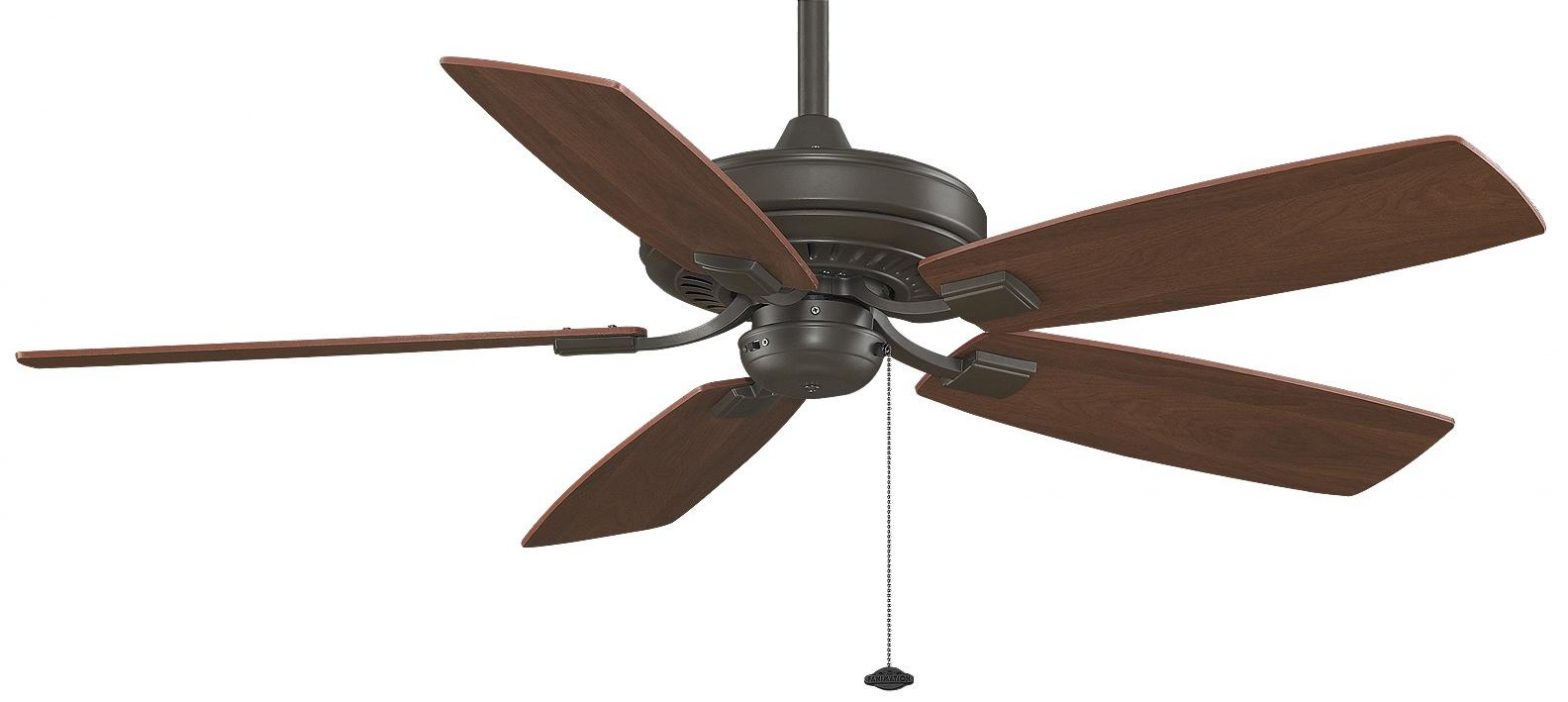
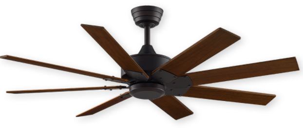
FANIMATION Levon Custom Dc Ceiling Fan
Important Safety Instructions
WARNING: To avoid fire, shock and serious personal injury, follow these instructions.1. Read your owner’s manual and safety information before installing your new fan. Review the accompanying assembly diagrams.2. Before servicing or cleaning unit, switch power off at service panel and lock service panel disconnecting means to prevent power from being switched on accidentally. When the service disconnecting means cannot be locked, securely fasten a warning device, such as a tag, to the service panel.3. Be careful of the fan and blades when cleaning, painting, or working near the fan. Always turn off the power to the ceiling fan before servicing.4. Do not insert anything into the fan blades while the fan is operating.5. Do not operate reversing switch until fan blades have come to a complete stop.6. The appliance is not intended for use by young children or infirm persons without supervision. Young children should be supervised to ensure that they do not play with the appliance.
Additional Safety Instructions
- To avoid possible shock, be sure electricity is turned off at the fuse box before wiring, and do not operate fan without blades.
- All wiring and installation procedures must satisfy National Electrical Codes (ANSI/ NFPA 70) and Local Codes. The ceiling fan must be grounded as a precaution against possible electrical shock. Electrical installation should be made or approved by a licensed electrician.
- The fan base must be securely mounted and capable of reliably supporting at least 35 lbs. See page 6 of owner’s manual for support requirements. Consult a qualified electrician if in doubt.
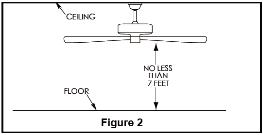
- The fan must be mounted with the fan blades at least 7 feet from the floor to prevent accidental contact with the fan blades.
- Follow the recommended instructions for the proper method of wiring your ceiling fan. If you do not have adequate electrical knowledge or experience, have your fan installed by licensed electrician.
WARNING:
TO REDUCE THE RISK OF ELECTRIC SHOCK, THIS FAN MUST BE INSTALLED WITH A GENERAL USE, ISOLATING WALL CONTROL/ SWITCH.WARNING: This product is designed to use only those parts supplied with this product and/or accessories designated specifically for use with this product. Using parts and/or accessories not designated for use with this product could result in personal injury or property damage.WARNING: To reduce the risk of personal injury, do not bend the blade bracket (flange or blade holder) when installing the brackets, balancing the blades, or cleaning the fan. Do not insert foreign objects in between rotating fan blades.This device complies with Part 15 of the FCC Rules. Operation is subject to the following two conditions:(1) This device may not cause harmful interference, and (2) this device must accept any interference received, including interference that may cause undesired operation. If the intentional radiator can be classified as a Class B digital device or a PCperipheral, then shall include the following or equivalent:
Note: This equipment has been tested and found to comply with the limits for Class B digital device, pursuant to part 15 of the FCC Rules. These limits are designed to provide reasonable protection against harmful interference in a residential installation.
This equipment generates, uses and can radiate radio frequency energy and, if not installed and used in accordance with the instructions, may cause harmful interference to radio or television reception, which can be determined by turning the equipment off and on, the user is encouraged to try to correct the interference by one or more of the following measures:
- Reorient or relocate the receiving antenna.
- Increase the separation between the equipment and the receiver.
- Connect the equipment into an outlet on a circuit different from that to which the receiver is connected.Consult the dealer or an experienced radio/TV technician for help.Note: For a Class A digital device, statements of 15. 105(a) must be included when appropriate for the device in question.
WARNING:
- TO REDUCE THE RISK OF ELECTRIC SHOCK, THIS FAN MUST BE INSTALLED WITH A GENERAL USE, ISOLATING WALL CONTROL/ SWITCH.
- This product is designed to use only those parts supplied with this product and/or accessories designated specifically for use with this product. Using parts and/or accessories not designated for use with this product could result in personal injury or property damage.
- To reduce the risk of personal injury, do not bend the blade bracket (flange or blade holder) when installing the brackets, balancing the blades, or cleaning the fan. Do not insert foreign objects in between rotating fan blades.This device complies with Part 15 of the FCC Rules. Operation is subject to the following two conditions:(1) This device may not cause harmful interference, and (2) this device must accept any interference received, including interference that may cause undesired operation. If the intentional radiator can be classified as a Class B digital device or a PCperipheral, then shall include the following or equivalent:
Note: This equipment has been tested and found to comply with the limits for Class B digital device, pursuant to part 15 of the FCC Rules. These limits are designed to provide reasonable protection against harmful interference in a residential installation.
This equipment generates, uses and can radiate radio frequency energy and, if not installed and used in accordance with the instructions, may cause harmful interference to radio or television reception, which can be determined by turning the equipment off and on, the user is encouraged to try to correct the interference by one or more of the following measures:
- Reorient or relocate the receiving antenna.
- Increase the separation between the equipment and the receiver.
- Connect the equipment into an outlet on a circuit different from that to which the receiver is connected.Consult the dealer or an experienced radio/TV technician for help.Note: For a Class A digital device, statements of 15. 105(a) must be included when appropriate for the device in question.
Unpacking Instructions
For your convenience, check-off each step. As each step is completed, place a check mark. This will ensure that all steps have been completed and will be helpful in finding your place should you be interrupted.
WARNINGDo not install or use fan if any part is damaged or missing. This product is designed to use only those parts supplied with this product and/or any accessories designated specifically for use with this product by Fanimation. Substitution of parts or accessories not designated for use with this product by Fanimation could result in personal injury or property damage. Contact your retail store for missing or damaged parts.
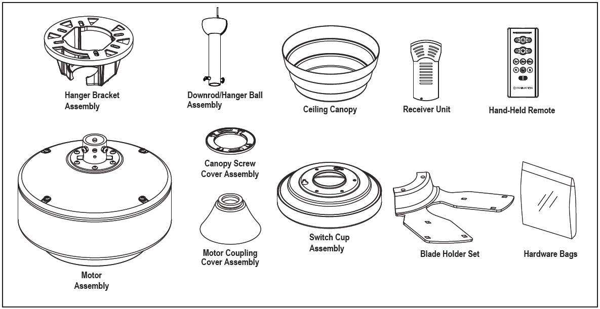
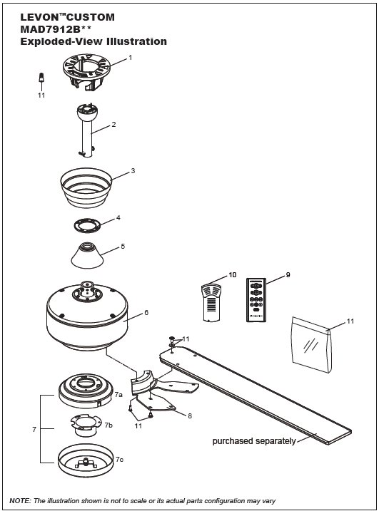
Check to see that you have received the following parts:NOTE: If you are uncertain of part description, refer to exploded view illustration.
Energy Efficient Use of Ceiling Fans
Ceiling fan performance and energy savings rely heavily on the proper installation and use of the ceiling fan. Here are a few tips to ensure efficient product performance.Choosing the Appropriate Mounting LocationCeiling fans should be installed, or mounted, in the middle of the room and at least 7 feet from floor to the blade and 18 inches from wall to the blade. If ceiling height allows, install the fan 8 – 9 feet from floor to the blade for optimal airflow. Consult your Fanimation Retailer for optional mounting accessories.Turn Off When Not in the RoomCeiling fans cool people, not rooms. If the room is unoccupied, turn off the ceiling fan to save energy.
Using the Ceiling Fan Year RoundSummer Season: Use the ceiling fan in the counter-clockwise direction. The airflow produced by the ceiling fan creates a wind-chill effect, making you “feel” cooler. Select a fan speed that provides a comfortable breeze, lower speeds consume less energy.Winter Season:Reverse the motor and operate the ceiling fan at low speed in the clockwise direction. This produces a gentle updraft, which forces warm air near the ceiling down into the occupied space.Remember to adjust your thermostat when using your ceiling fan – additional energy and dollar savings could be realized with this simple step!
Electrical and Structural Requirements
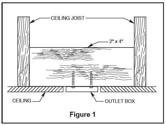
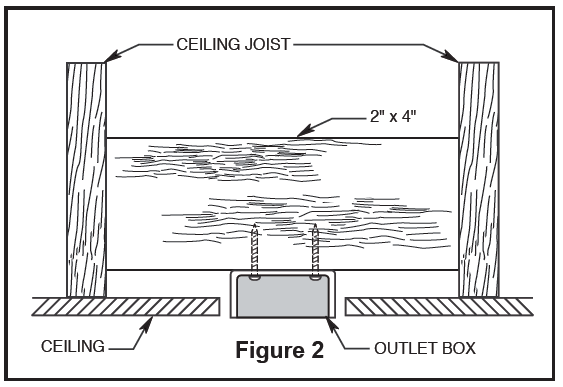
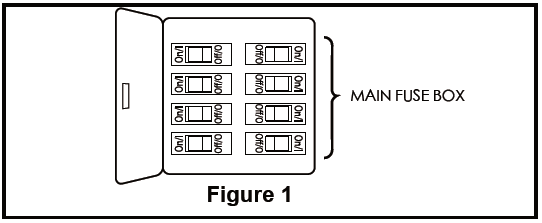
Your new ceiling fan will require a grounded electrical supply line of 120 volts AC, 60 HZ, 15 Amp Circuit. Electrical code requires use of a fan-rated outlet box to support the extra weight and motion associated with a ceiling fan. A fan-rated box will be labeled as such and typically supports up to a 70lb ceiling fan. Fan-Rated Outlet Boxes vary in ratings and design. Ensure the ratings of your ceiling fan outlet box meet the requirements for the ceiling fan being installed. Figure 1, Figure 2 and Figure 3 depicts different structural configurations that may be used for mounting the outlet box.Low profile box (Figure 1) joist or block. It’s used if only one cable is coming into the box. It is also available in a saddle-mount configuration.Deep box (Figure 2) between joists and is roomy enough to handle more than one cable.
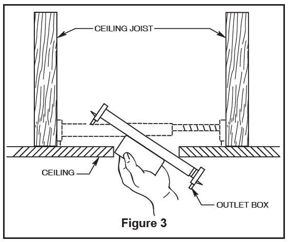
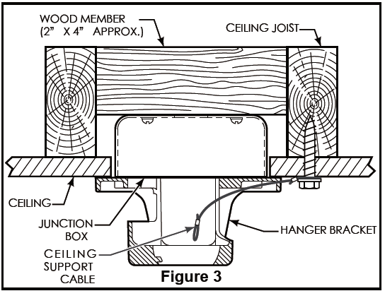
Deep box with brace (Figure 3) Paired with a deep box, this hanger is meant to span between two joists and takes the place of wooden blocking.
WARNING:
- To reduce the risk of fire, electrical shock, or personal injury, mount fan to outlet box marked acceptable for fan support of 15.88 kg (35 lbs) or less. Use screws supplied with outlet box. Most outlet boxes commonly used for support of light fixtures are not acceptable for fan support and may need to be replaced. Consult a qualified electrician if in doubt.
- Turning off wall switch is not sufficient. To avoid possible electrical shock, be sure electricity is turned off at the main fuse box before wiring. All wiring must be in accordance with National and Local codes and the ceiling fan must be properly grounded as a precaution against possible electrical shock.
- To avoid fire or shock, follow all wiring instructions carefully. Any electrical work not described in these instructions should be done or approved by a licensed electrician.
- Do not operate this fan with a variable (Rheostat) wall controller or dimmer switch. Doing so could result in damage to the ceiling fan’s remote control unit.
To reduce the risk of fire, electrical shock, or personal injury, mount fan to outlet box marked acceptable for fan support of 15.88 kg (35 lbs) or less. Use screws supplied with outlet box. Most outlet boxes commonly
How to Assemble Your Ceiling Fan
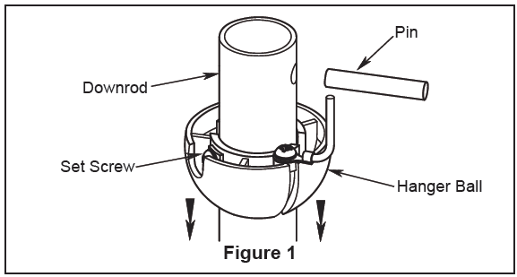
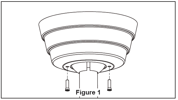
- Remove the hanger ball portion from the downrod /hanger ball assembly by loosening the set screw in the hanger ball until the ball falls freely down the downrod. Remove the pin from the downrod, then remove the hanger ball. Retain the pin and hanger ball for reinstallation in Step 6 (Figure 1).

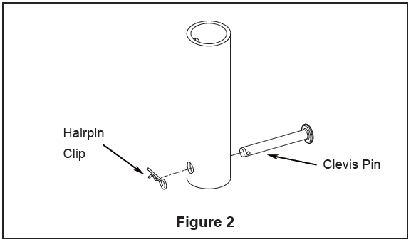
- Remove the hairpin clip and clevis pin from the bottom of downrod. Retain the pin and clip for reinstallation in Step 4 (Figure 2).
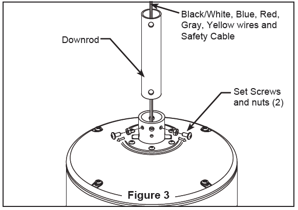
- Loosen the two set screws and locking nuts in the downrod support of the motor assembly. Route the black/white, blue, red, gray and yellow wires and safety cable through the downrod. (Figure 3)
- Install the clevis pin, hairpin clip and tighten set screws. The clevis pin and hair pin clip must be properly installed to prevent the set screws from working loose. (Figure 4)WARNING: It is critical that the clevis screw in the downrod support is properly installed and the setscrews and nuts are securely tightened. Failure to verify that the clevis screw, nuts, hairpin clip and setscrews are properly installed could result in the fan falling.
- Route wires and safety cable through motor coupling cover, canopy screw cover and ceiling canopy. (Figure 5)
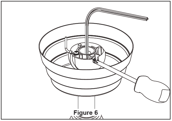
- Reinstall the hanger ball on the downrod as follows. Route the black/white, blue, red, gray and yellow wires and safety cable through the hanger ball. Position the pin through the two holes in the downrod and align the hanger ball so the pin is captured in the groove in the top of the hanger ball. Pull the hanger ball up tight against the pin. Securely tighten the set screw in the hanger ball. A loose set screw could cause fan wobble. (Figure 6)
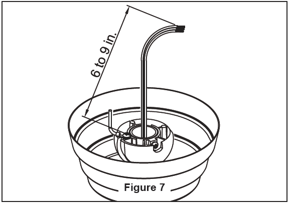
- Cut off excess lead wire approximately 6 to 9 inches above top of the top of the downrod. Strip insulation off 1/2 inch from the end of each lead wire. (Figure 7)NOTE: All set screws must be checked, and retightened where necessary, before installation.
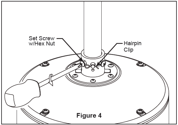 WARNING: It is critical that the clevis screw in the downrod support is properly installed and the setscrews and nuts are securely tightened. Failure to verify that the clevis screw, nuts, hairpin clip and setscrews are properly installed could result in the fan falling.
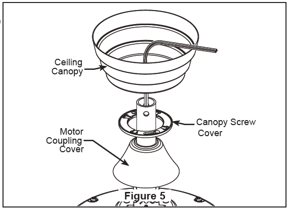
 NOTE: All set screws must be checked, and retightened where necessary, before installation.
How to Hang Your Ceiling Fan
WARNING
- To avoid possible electrical shock, be sure electricity is turned off at the main fuse box before hanging. (Figure 1) NOTE: If you are not sure if the outlet box is grounded, contact a licensed electrician for advice, as it must be grounded for safe operation.
- The fan must be hung with at least 7´ of clearance from floor to blades. (Figure 2)
- The outlet box must be securely anchored and capable of withstanding a load of at least 35 lbs. Hanger bracket must seat rmly against outlet box. If the outlet box is recessed, remove wallboard until bracket contacts box. If bracket and/or outlet box are not securely attached, the fan could wobble or fall.
- Do not connect fan blades until the fan is completely installed. Hanging fan with blades connected may result in damage to the fan blades.
- Using the 3⁄8˝˝ x 2˝˝ lag bolt and flat washerr, attach safety cable to ceiling joist or wood structural memberr.. The lag bolt will pass through the flat washerr, safety cable loop, and into the building structure (Figure 3). You will first drill a ¼˝ pilot hole into the building structure to prevent splitting or cracking.
- Securely attach the hanger bracket to ceiling junction box acceptable for ceiling fan support..NOTE: Ceiling support cable cannot be secured to junction box only, it must be directly secured to ceiling joist or structural member using the ⅜˝˝ x 2˝˝ lag bolt and flat washer.. (Figure 3
- Make sure the electrical supply wires, including the hanger bracket grounding wire and safety cable are pulled through the downrod, between the hanger bracket and the junction box so that electrical connections can be made later
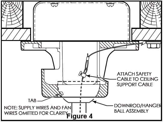
- Carefully lift the fan and seat the download/hanger ball assembly on the hanger bracket that was just attached to the ceiling joist. Be sure the groove in the ball is lined up with tab on the hanger bracket. (Figure 4)
- Attach the safety cable to ceiling support cable. Slide cable clamp onto safety cable (from fan). Place the end of cable through the loop of ceiling support cable. Pull as much cable through loop as possible. Feed end of cable into clamp hole and firmly tighten screw (Figure 4). Cut of excess safety cable.
How to Wire Your Ceiling Fan
NOTE: If fan or supply wires are different colors than indicated, have this unit installed by a qualified electrician.
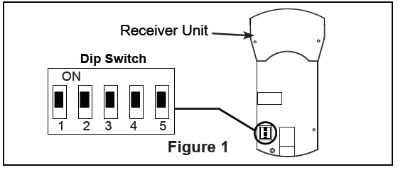
- To set the code on receiver unit, slide dip switches to the same positions as set on the remote. (Figure 1)NOTE: The remote unit has 32 different code combinations. To prevent possible interference from or to other remote units, simply change the combination code in the remote and receiver. Factory setting is all up. Do not use this position.WARNING: To avoid possible electrical shock, be sure electricity is turned off at the main fuse box before wiring (Figure 2).
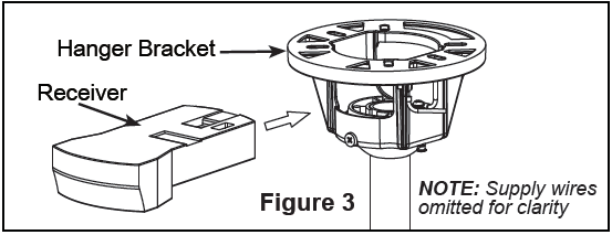
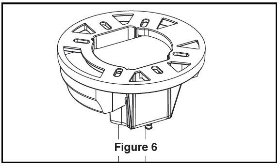
- Slide the receiver into the hanger bracket as shown in Figure 3.
- Connect wires using connectors as shown in Figure 4.WARNING: Check to see that all connections are tight, including ground, and that no bare wire is visible at the wire connectors. Do not operate fan until the blades are in place. Noise and motor damage could result.
- After connections have been made, slide the receiver into the hanger bracket, taking care not to pinch the wires and put the white and green leads to one side and the black leads towards the other side. The wires should be spread apart with the grounded conductor and the equipment-grounding conductor on one side of the outlet box and the ungrounded conductor on the other side.(Figure 5)
- If your receiver slid out of the bracket at all while wiring your fan, slide it all the way into the hanger bracket, taking care not to pinch the wires. The canopy comes up to cover the receiver and hanger bracket. (Figure 6)
 WARNING: To avoid possible electrical shock, be sure electricity is turned off at the main fuse box before wiring (Figure 2).
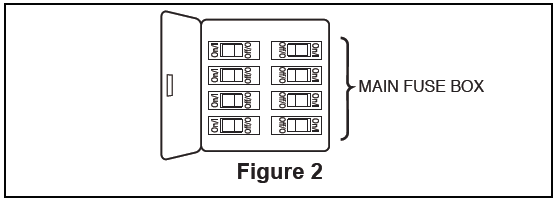
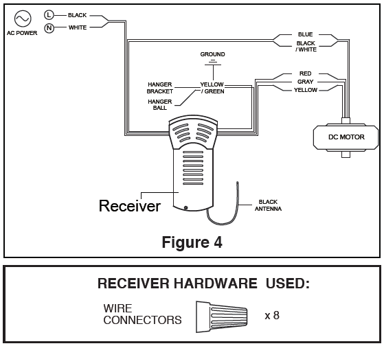 WARNING: Check to see that all connections are tight, including ground, and that no bare wire is visible at the wire connectors. Do not operate fan until the blades are in place. Noise and motor damage could result.
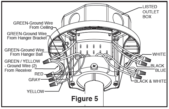
Installing the Canopy Housing
NOTE: This step is applicable after the necessary wiring is completed.
- Remove the two shoulder screws in the hanger bracket. Align holes in the canopy with holes in the hanger bracket and securely attach canopy using the two shoulder screws from the hanger bracket. (Figure 1)
- Securely attach and tighten the canopy screw cover over the shoulder screws in the hanger bracket utilizing the keyslot twist-lock feature. (Figure 2)
How to Assemble Your Ceiling Fan Blades and Cap
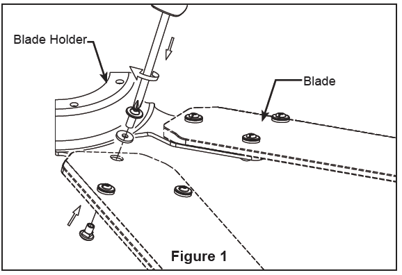
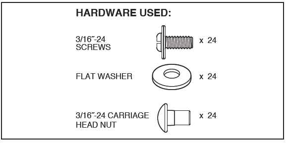
- Lay the side of the blade holder on a flat surface with the inside of the blade holder facing up. Assemble the blade to the blade holder with the carriage nuts, flat washer, and screws. Make sure that the blades are fully seated against the blade holders and tighten screws. (Figure 1)NOTE: You will find the fan blade set packed in its own carton and the blade holders and hardware bag in the fan box.CAUTION: Do not connect fan blades until the fan is completely installed. Installing the fan with blades assembled may result in damage to the fan blades.
- Attach assembled blades and blade holders to the motor hub using the provided screws with lock washers. Make sure the screws securing the blade holders to the motor hub are tight and that the blade holders are properly seated. (Figure 2)NOTE: Periodically check Blade Holder hardware and re-secure if necessary. (see Maintenance below)WARNING: To reduce the risk of personal injury, do not bend the blade holders when installing, balancing the blades or cleaning the fan. Do not insert foreign objects in between the rotating blades.
- Remove the six screws in the motor assembly and retain the screws for reassembly in steps 4 and 5. (Figure 3)
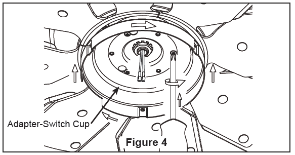
- Attach the adapter-switch cup to the support flange using three of the previously removed six screws and fully tighten. (Figure 4)
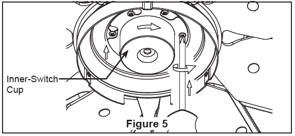
- Attach the inner-switch cup to the support flange using the remaining three screws and fully tighten.(Figure 5)
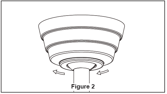
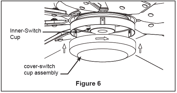
- Assemble the cover-switch cup assembly to the inner-switch cup by twisting in a clockwise direction.(Figure 6)
 CAUTION: Do not connect fan blades until the fan is completely installed. Installing the fan with blades assembled may result in damage to the fan blades.
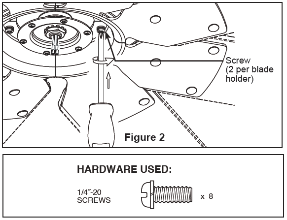 NOTE: Periodically check Blade Holder hardware and re-secure if necessary. (see Maintenance below)WARNING: To reduce the risk of personal injury, do not bend the blade holders when installing, balancing the blades or cleaning the fan. Do not insert foreign objects in between the rotating blades.
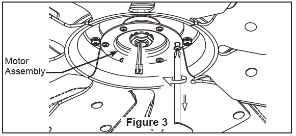
How to Operate Your Ceiling Fan
1. IMPORTANT: Using a full range dimmer switch (not included) to control fan speed will damage the fan. To reduce the risk of fire or electrical shock, do not use a full range dimmer switch to control the fan speed. (Figure 1)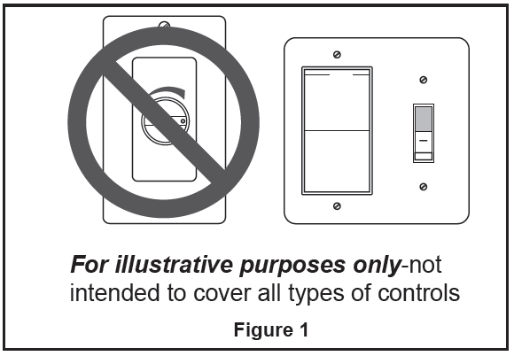 Restore electrical power to the outlet box by turning the electricity on at the main fuse box. (Figure 2)
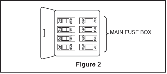 WARNING: Check to see that all connections are tight, including ground, and that no bare wire is visible at the wire connectors, except for the ground wire. Do not operate fan until the blades are in place. Noise and fan damage could result.Do not operate this fan with a variable (Rheostat) wall controller or dimmer switch. Doing so could result in damage to the ceiling fan’s remote control unit.To make fan operational, install two 3V batteries (included) in hand-held remote transmitter, with fan power off. Then, follow the remote code setting process. If not used for long periods of time, remove battery to prevent damage to transmitter. Store the remote away from excessive heat or humidly. (Figure 3)
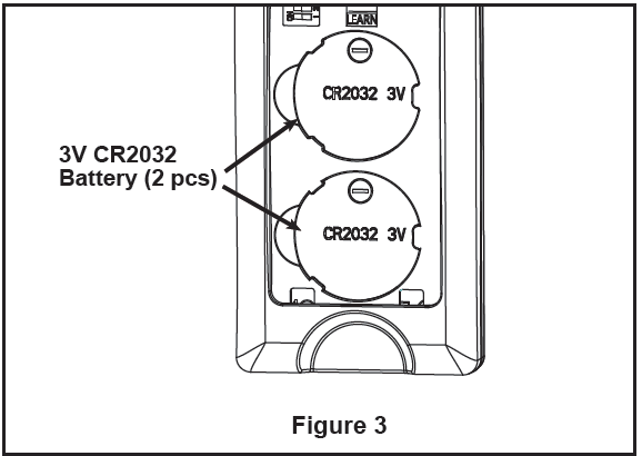 4. If you have multiple fans and want to program all fans to one handheld control. Slide the Dip Switch with the same position in ALL receiver to ONE handheld to set up the code for each fans and follow Step 1 of the remote control speed set up process. Each fan needs to be no more than 30 feet from the handheld control that you would like to program. Please note the wall switch that controls the power to your fan(s) should be in the off position until you are ready to program your handheld remote(s).
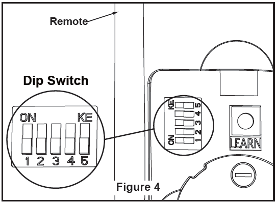 If you have multiple fans and want to program each fan to separate handheld controls. Slide the Dip Switch with the same position in both receiver and handheld to set up the code for each fans and follow Step 1 of the remote control speed set up process below. Repeat these steps for each fan that you would like to program to a separate handheld remote. Please note that the wall switch that controls the power to your fan(s) should be in the off position until you are ready to program your handheld remote(s).
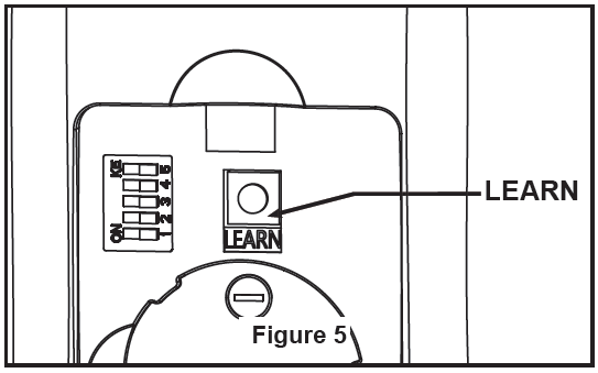 6. To set the remote code with a small screwdriver or ball point pen (neither included), slide dip switches firmly up or down to same as receiver unit. (Figure 4)NOTE:Factory setting is all up. Do not use this position. The remote unit has 32 different code combinations.To prevent possible interference from or to other remote units, simply change the combination code in the remote and receiver.
7. Remote Control Speed (RPM) Setting Process : (Figure 5)
- After installing and wiring the unit, restore power to your fan by ensuring that the breaker and wall switch that controls the power supply is moved to the on position, press and hold the “LEARN” button inside of the battery compartment of the handheld remote control for 1-3 seconds.
- You must press the “LEARN” button within 30 seconds of restoring power to the fan.
- When restoring power to your fan at the wall switch and breaker, DO NOT press any button(s) on the handheld remote control before pressing the “LEARN” button, otherwise the fan will fail the learn procedure.
- If you press any button(s) on the handheld remote control before pressing the “LEARN” button, please turn the wall switch that controls the power to the fan to the off position then on again, and start the process beginning with Step 1 above.
- When you press the “LEARN” button, the fan will make one musical sound and light blink once if with light and start to run beginning the control set up process.
- DO NOT press any button(s) after pressing the LEARN button while the fan is programming or it will fail to program.
- The fan will run in forward direction for approximately 3 minutes.
- When the fan stops running after approximately 3 minutes, the fan will make two musical sounds and light blink twice if with light that means that the handheld remote control and speed set up process is complete.
- The fan is now ready for normal use.
NOTE: If you want to change the blades: turn the power off→ change the blades→ turn the power on→ perform the control setting process.8. Remote functions: (Figure 6)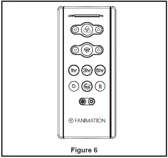
- Indicator LED light: fan speed and light dimmer indicator
- button: Tap once to turn off the fan. Press and hold this button for 5 seconds to turn on or turn off the buzzer.
- Fan Speed:
- Turn on fan and turn speed up.
- Turn on fan and turn speed down.
- Light button: Turn ON\OFF the light.
- Increase light output level.
- Decrease light output level.
- Sleep Timer:
- The fan and light will turn off after 1 hour.
- The fan and light will turn off after 3 hours.
- The fan and light will turn off after 6 hours.
- Home Away: Tap this button, the light will blink twice signaling this feature is on; the fan will turn off and the light will randomly turn on and off while you are away. Pressing any button will cancel the feature.
- Fresh Air: Fan speed will modulate to simulate a natural breeze.
- Safe Exit: Tap once, the light will blink once; fan and light will turn off after 1 minute. Pressing any button will cancel this feature.
- Reverse button:
- Summer- The fan runs counterclockwise. Airflow will provide a downward cooling breeze.
- Winter- The fan runs clockwise. Airflow will force warm air downward without a noticeable breeze.
How to Set Up the fanSync App (optional)
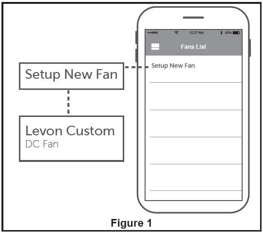
Visit the Apple App Store or the Google Play Store which can be found at www.fanimation.com/fansync, to download the free fanSync app.IMPORTANT: Your smart device must have Bluetooth turned on to use fanSync.
- Open the fanSync app and tap Setup New Fan to begin setup. (Figure 1)
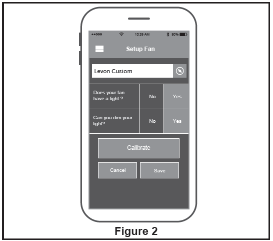
- Name your fan, answer light questions, choose save and your fan will be ready to operate. (Figure 2)
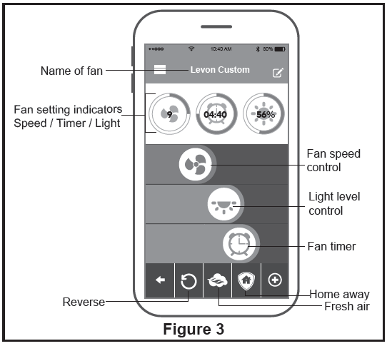
- Fan functions as shown. (Figure 3)
How to Install Your Remote Control
Installing Wall Holder: (Figure 1)
Attach wall plate using the two provided screws.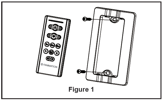
Maintenance
Periodic cleaning of your new ceiling fan is the only maintenance that is needed.When cleaning, use only a soft brush or lint free cloth to avoid scratching t he finish. Abrasive cleaning agents are not required and should be avoided to prevent damage to finish.
CAUTION: Do not use solvents when cleaning your ceiling fan. It could damage the motor or the blades and create the possibility of electrical shock.
Parts List
| Ref.# | Description | Part # |
| 1 | Hanger Bracket Assembly | |
| 2 | Hanger Ball/Downrod Assembly | ADR1-6** |
| 3 | Canopy | PG165** |
| 4 | Canopy Screw Cover Assembly | AP260** |
| 5 | Motor Coupling Cover Assembly | AP1115** |
| 6 | Motor Assembly | AMA7912B** |
| 7 | Switch Cup Assembly | |
| 7a | Adapter Switch Cup | P791201** |
| 7b | Inner-Switch Cup | P791203BL |
| 7c | Cover-Switch Cup Assembly | AP791202** |
| 8 | Blade Holder Set | AP880001** |
| 9 | Hand-Held Remote | TR205D |
| 10 | Receiver | RCCD791200 |
|
11 |
Hardware Bag Containing: |
HDWMAD7912B** |
| Bag Assembly Safety Cable | ||
| Wire Connectors (4) | ||
| Blade Holder Mounting Hardware Bag Containing: | ||
| h Lock Washers (9) | ||
| Blade Mounting Hardware Bag Containing: | ||
| 5) | ||
| Flat Washer (25) |
LEVON CUSTOM MAD7912B** Exploded-
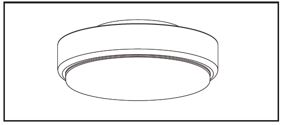
Optional Light Kit
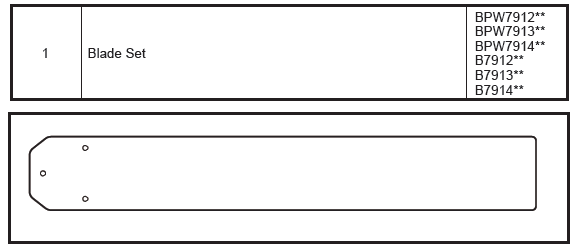
Optional Fan Blade
Trouble Shooting
| Trouble | Probable Cause | Suggested Remedy |
| 1. FAN WILL NOT START | 1. Fuse or circuit breaker blown.
2. Loose power line connections to the fan, or loose switch wire connections in the switch housing.
3. Dead battery in remote control. |
1. Check main and branch circuit fuses or circuit breakers.
2. Check line wire connections to fan and switch wire connections in the switch housings. CAUTION: Make sure main power is turned off !
3. Replace with fresh battery. |
| 2. FAN SOUNDS NOISY | 1. Blades not attached to fan.
2. Loose screws in motor housing.
3. Screws securing fan blade holders to motor hub are loose.
4. Wire connectors inside housing rattling.
5. Motor noise caused by solid state variable speed control.
6. Screws holding blades to blade holders are loose. |
1. Attach blades to fan before operating.
2. Check to make sure all screws in motor housing are snug (not over-tight).
3. Check to make sure the screws which attach the fan blade holders to the motor hub are tight.
4. Check to make sure wire connectors in switch housing are not rattling against each other or against the interior wall of the switch housing.
CAUTION: Make sure main power is turned off !
5. Some fan motors are sensitive to signals from solid-state variable speed controls. Solid-state controls are not recommended, choose an alternative control method.
6. Tighten screws securely. |
| 3. FAN WOBBLES EXCESSIVELY | 1. Setscrew and nut in downrod support is loose.
2. Setscrew in downrod/hanger ball assembly is loose.
3. Screws securing fan blade holders to motor hub are loose.
4. Blade holders not seated properly.
5. Hanger bracket and/or ceiling outlet box is not securely fastened.
6. Fan blades out of balance. |
1. Tighten both setscrews and nuts securely in downrod support.
2. Tighten the setscrew in the downrod/hanger ball assembly.
3. Check to be sure screws which attach the fan blade holders to the motor hub are tight.
4. Check to be sure the fan blade holders seat firmly and uniformly to the surface of the motor housing. If holders are seated incorrectly, loosen the screws and retighten.
5. Tighten the hanger bracket screws to the outlet box, and secure outlet box.
6. Interchanging position of fan blades can redistribute the weight and result in a smoother operation. For example, exchange blades in positions 1 and 3 or 1 and 4. If this does not improve wobble, exchange 2 and 4 or 2 and 5. |
| 4. NOT ENOUGH AIR MOVEMENT | 1. If possible, consider using a longer downrod. (not included, you can buy the longer downrod from fanimation.com). |
![]()
References
[xyz-ips snippet=”download-snippet”]