
HERO SERIES Fresh Air Appliance (HRV) Installation and Operation Manual
PARTS IN THE BOX
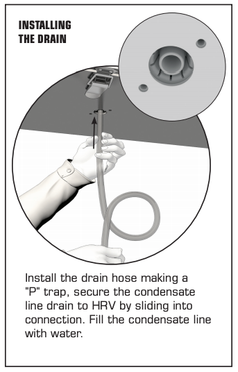
Heat Recovery Ventilator, 1 pcHanging Bracket, 1 pcDrain Hose Kit, 1 pcOperation and Installation Manual, 1 pc
Your ventilation system should be installed in conformance with the appropriate provincial requirements or, in the absence of such requirements, with the current edition of the National Building Code, and / or ASHRAE’s “Good Engineering Practices”.
 REGISTER THIS PRODUCT TO BE REMINDED OF SUGGESTED PRODUCT CARE SCHEDULE
registration.fantech.app
United States 800.747.1762
Canada 800.565.3548
Fantech reserves the right to modify, at any time and without notice, any or all of its products’ features, designs, components and specifications to maintain their technological leadership position.
Please visit our website www.fantech.net for more detailed technical information.

PLEASE READ AND SAVE THESE INSTRUCTIONS
For residential use only
Before installation careful consideration must be given to how this system will operate if connected to any other piece of mechanical equipment, i.e., a forced air furnace or air handler operating at a higher static pressure. After installation, the compatibility of the two pieces of equipment must be confirmed by measuring the airflow of the Heat Recovery Ventilator using the balancing procedure found in this manual. It is always important to assess how the operation of any HRV may interact with vented combustion equipment (i.e., Gas Furnaces, Oil Furnaces, Wood Stoves, etc.)

Products are designed and manufactured to provide reliable performance, but they are not guaranteed to be 100% free of defects. Even reliable products will experience occasional failures, and this possibility should be recognized by the user. If these products are used in a life support ventilation system where failure could result in loss or injury, the user should provide adequate back-up ventilation, supplementary natural ventilation or failure alarm system, or acknowledge willingness to accept the risk of such loss or injury.
Your ventilation system should be installed in accordance with the local building code that is in effect, in absence of such requirements, it is recommenced to check with local authorities having jurisdiction in your area prior to installing this product.

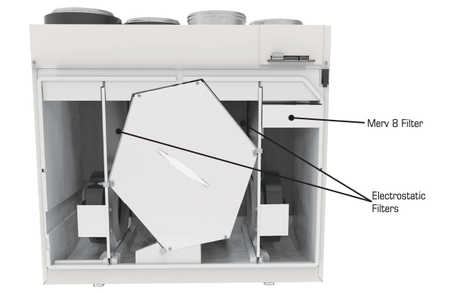
The MERV8 supply filter provided with the unit is intended for areas that it is required. In most cases the MERV8 supply filter is not required and it becomes optional at the home owner’s discretion. Installing the MERV8 supply filter or other MERV filter options will affect the maximum airflow of the unit, please refer to product documentation for more information.
Technical data was obtained from published results of test relating to CSA C439 Standards. This data was optained without the use of the MERV8 supply filter.
INSTALLATION TYPES
Example only – duct configuration may differ depending on the model.
HRV DUCTING FOR FULLY DEDICATED SYSTEM
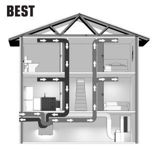
- Stale air is drawn from areas requiring local exhaust (bathroom, kitchen, laundry room).
- Fresh air is distributed to habitable rooms (bedrooms, living room)
- The HRV’s airflow must be balanced after installation using the procedure found in the section “AIRFLOW BALANCING.”
Suggested for:
- Hydronic baseboard
- In floor heating
- Electric baseboard
- Mini split heat pump
Benefits:
Provides the best fresh air distribution in the house; lowest operation cost since the furnace/air handler unit is not needed.
Make sure the HRV is capable of meeting the required airflow rate.
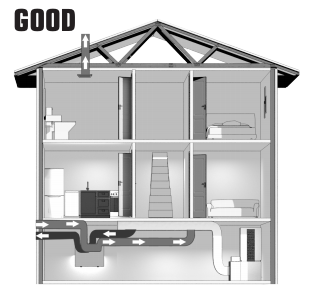
HRV/FURNACE DUCTING FOR PARTIALLY DEDICATED SYSTEM

- The furnace blower is set to run continuously or interconnected with HRV for proper fresh air distribution. See furnace electrical connection on page 12.
- Stale air is drawn from areas requiring local exhaust (bathroom, kitchen, laundry room).
- Fresh air is supplied to the return air plenum of the furnace.
- Due to the difference in pressure, HRV’s airflow must be balanced on site using the procedure found in the section “AIRFLOW BALANCING.”
* In the case of a multi-zone system, please contact Fantech customer service prior to installing any installation type requiring the use of the furnace interlock
Suggested for:
- Central furnace
- When ducting fresh air to living area is not possible or practical
Benefits:
Conditions the fresh air prior to distributing it throughout the house
- The furnace blower is set to run continuously or interconnected with HRV for proper fresh air distribution. See furnace electrical connection on page 12.
- A minimum separation of 1 m (39’’) is recommended between the two direct connections.
- The HRV’s exhaust air connection should be upstream of the HRV’s supply air connection to prevent exhausting any fresh air.
- Due to the difference in pressure, HRV’s airflow must be balanced on site using the procedure found in the section “AIRFLOW BALANCING.”
* In the case of a multi-zone system, please contact Fantech customer service prior to installing any installation type requiring the use of the furnace interlock”
Suggested for:
- When bathroom and kitchen already have local exhaust system
- May be suitable for retrofitting
Benefits:
Least expensive installation type
INSTALLING THE OUTDOOR VENTS
RECOMMENDED INSTALLATION
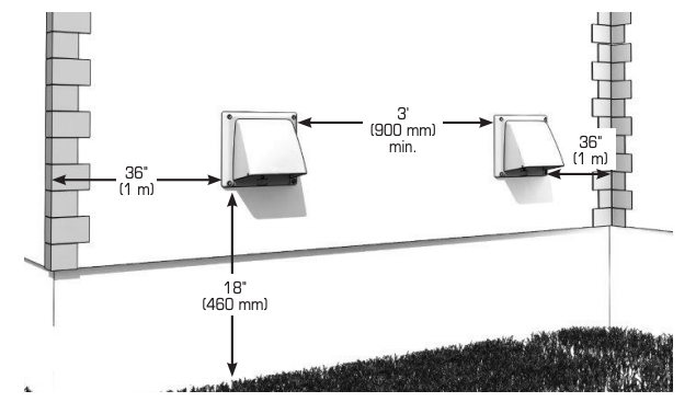
Intake
- Should be located upstream of prevailing winds from exhaust
- At a minimum of 900 mm (3′) away from dryer vents and furnace exhaust (medium or high efficiency furnaces), driveways, oil fill pipes, gas meters, or garbage containers.
- Do not locate in the garage, attic, crawl space, or underneath deck.
Locating the Exhaust Weatherhood
- Not near a gas meter, electric meter or a walkway where fog or ice could create a hazard
- Do not locate in a garage, workshop or other unheated space
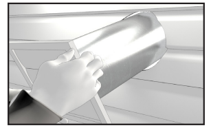
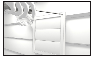
INSTALLING THE VENTS
A well designed and installed ducting system will allow the HRV to operate at its maximum efficiency.
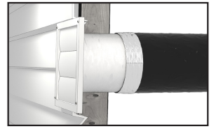
- The inner liner of the flexible insulated duct must be secured to the sleeve of the hood (as close to the outside as possible) and to the appropriate duct connection on the HRV.
- The insulation should remain full and not crushed.
- The outer liner, which acts as a vapor barrier, must be completely sealed to the outer wall and the HRV using tape and/or caulking.
- A good bead of high quality caulking (preferably acoustical sealant) will seal the inner flexible duct to both the HRV duct connection and the hood prior to securing them.
- To minimize airflow restriction, the flexible insulated duct that connects the two outside weatherhoods to the HRV should be stretched tightly and be as short as possible.
- Twisting or folding the duct will severely restrict airflow.
- Cut hole between wall studs

- Insert vent
- Secure vent with proper screws
- Seal using outdoor rated caulking
- Attach insulated duct from inside and tape


DUCT INSTALLATION
CONNECTING THE DUCTS TO THE HRV

INSTALLING DUCT TO HRV
Flexible Duct: Slide flexible ducting onto duct connection and affix with cable tie.
Solid Ducting: slide duct over duct connection, screw in place and seal.
SUPPLY AIR GRILLES LOCATION
Without a forced air furnace: fresh air should be supplied to all habitable rooms from high wall or ceiling locations. Grilles that diffuse the air comfortably are recommended.
With a forced air furnace: Connect to the furnace ductwork.
EXHAUST AIR GRILLE’S LOCATION
Draw stale air from the points where the worst air quality problems occur: bathroom, kitchen, and laundry room. Additional return air ducts from strategic locations may be installed. The furnace return duct may also be used to exhaust from.
As per building codes and installation requirements for combustion appliances: Air return ducts, or openings for air return, should not be placed in enclosed spaces containing combustion appliances that are subject to spillage.

- Ducts should be kept short and have as few bends or elbows as possible.
- 45º elbows are preferable to 90º.
- Use “Y“ ducts instead of “T” ducts whenever possible.
- All duct joints must be fastened with screws or duct sealant and wrapped with aluminum foil duct tape to prevent leakage.
- Galvanized ducting from the HRV to the living areas in the house is recommended whenever possible.
- To reduce noise a short length (approximately 300 mm, 12’’) of nonmetallic flexible insulated duct should be connected between the HRV and the supply/exhaust ductwork system.
- The main supply and return line to/from the HRV must have the same diameter as the duct connection or larger.
- Branch lines to the individual rooms may be as small as 100mm (4’’).
MOUNTING OPTIONS
WALL MOUNTING BRACKET INSTALLATION
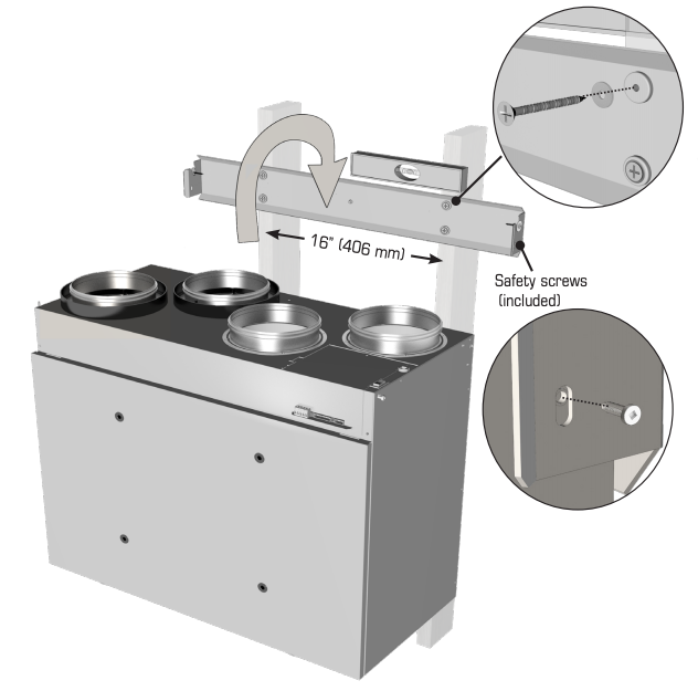
LOCATION
- Must be located in a conditioned space where it will be possible to conveniently service the unit.
- Typically located close to the outside wall where the hoods will be mounted.
- A utility room when basement is not possible.
Attic installation must meet the following conditions:
- Attic temperature must be above freezing conditions at all times and for best performance should be 12°C (54 °F).
- The attic is easily accessible for equipment maintenance and inspection.
CHAIN MOUNT INSTALLATION – OPTIONAL
* Hanging kit not included.
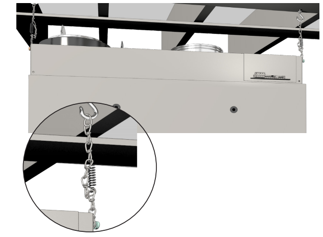
When wall mount bracket is not convenient. Use a chain kit (which includes hanging chains, 10-24 screws, spring, and hooks)
Install a spring on each chain as shown to support the unit’s weight and absorb vibrations.
DO NOT
Connecting appliances to the HRV is not recommended. These include:
- Clothes dryer
- Range top
- Stovetop fan
- Central vacuum system
- Bathroom exhaust fans unless they are specifically designed for this purpose
- These appliances may cause lint, dust or grease to collect in the HRV, damaging the unit.
Connecting any of these types of appliances to the HRV will void your warranty.
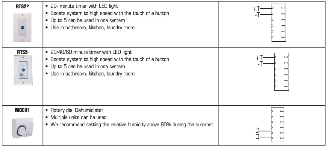
WALL CONTROLS
* Please see instruction manuals for individual controls for proper wiring and set up of control systems.
CENTRAL CONTROLS
These cannot be used with another central control

- Ensure that unit is not plugged when connecting the control
- Recirculation mode is only available with the “R” suffix at the end of the model number.

The wiring connectors can be removed for easier connection.
*Maintain polarity between control and HRV
(+ → + ; – → -)
AUXILIARY CONTROL –These controls can be paired with central controls or combined together.
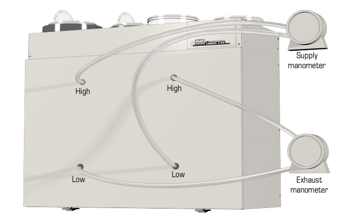
BALANCING
Balancing must be completed using the Fantech ECO-Touch® Programmable Touch Screen Wall Control
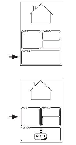
ENTERING BALANCING MODE
In the options menu during the initial 5 second countdown sequence, long press on “ECO” area for 5 seconds to enter basic balancing mode.
The supply and exhaust fans are adjusted on high speed only and the offsets are proportionally applied to the medium and low speed automatically.
 STAGE 1
(ADJUST LEVEL OF EXHAUST FAN IN HIGH SPEED):
- In this step, balance exhaust fan and measure airflow on the exhaust air side
- Pressing on “up” or “down” will adjust the fan speed in increments of 1%.
- Once the desired exhaust airflow is reached, press on “next” and move on to the next stage.
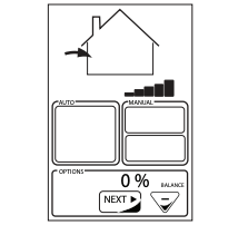 STAGE 2
(BALANCE SUPPLY FAN ONLY IN HIGH SPEED):
- In this step, balance supply fan and measure airflow on the supply air side
- Pressing on “up” or “down” will adjust the fan speed in increments of 1%.
- Once happy with the outcome, press on “next” to complete balancing
- The supply and exhaust offset values will be proportionally applied to low and medium speed as well.
WIRING DIAGRAM – HERO 120H, 150H, 200H

WIRING DIAGRAM – HERO 150H-EC, 250H-EC (CONT’D)
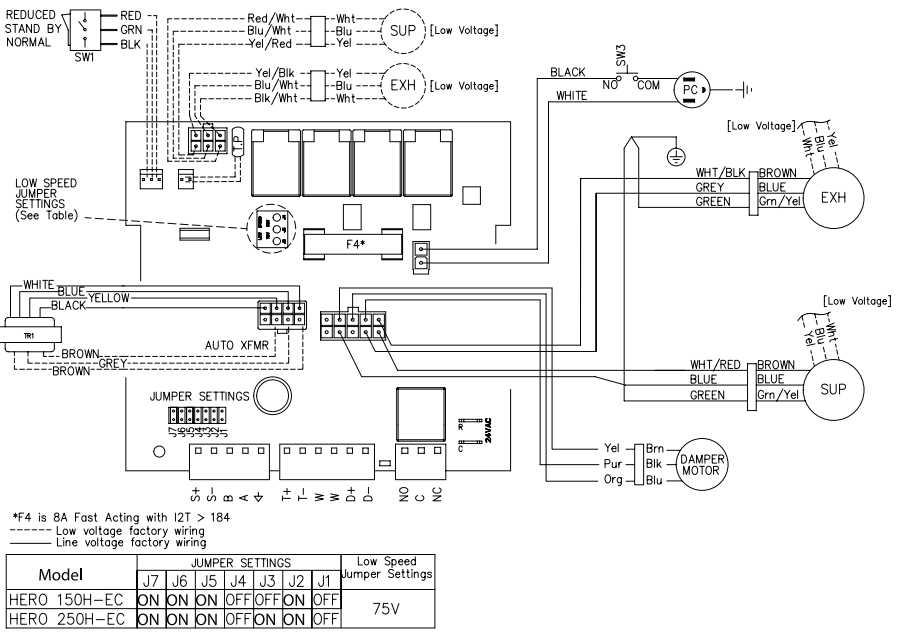
WIRING DIAGRAM (CONT’D)
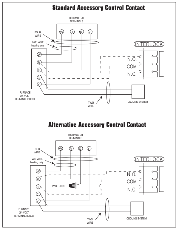
WIRING DIAGRAM TO FURNACE
FOR A FURNACE
CONNECTION TO A COOLING SYSTEM:
On some newer furnaces and older thermostats, energizing the R and G terminal at the furnace has the effect of energizing the Y at the thermostat and thereby turning on the cooling system. If you identify this type of thermostat, you must use the “Alternate Furnace Interlock Wiring.”
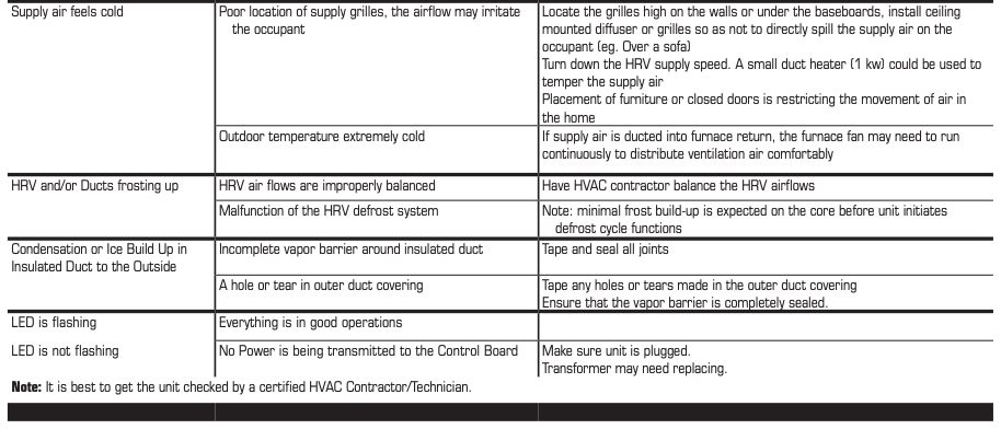
TROUBLESHOOTING

FILTER LOCATION
HRV MAINTENANCE CHART
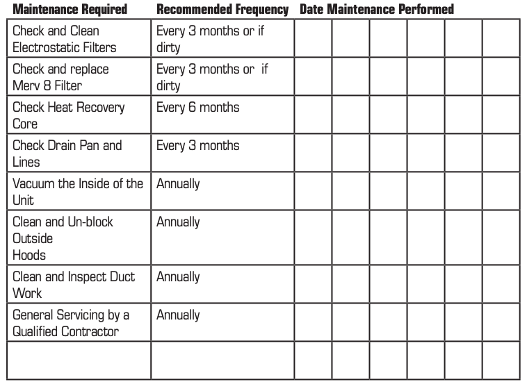
* Schedule may be altered to meet your own needs. More frequent servicing may be required depending on the severity of your home’s indoor and outdoor environments.
PARTS LIST
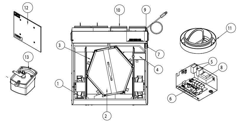
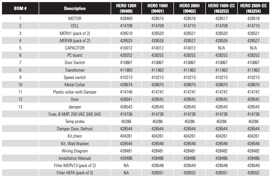
Fantech reserves the right to make technical changes.
For updated documentation please refer to www.fantech.net
FantechMD
References
[xyz-ips snippet=”download-snippet”]