
![]() Model: UCL192/FLEX/SCCT
Model: UCL192/FLEX/SCCT
![]()
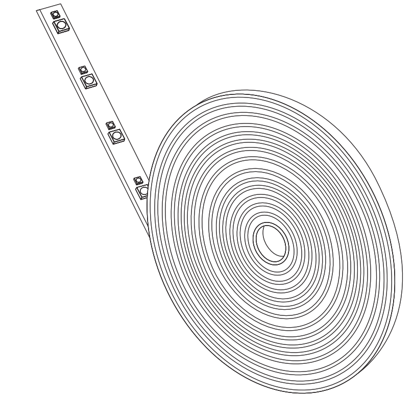
FLEXIBLE UNDER CABINET 192” TAPE LIGHT
IMPORTANT SAFETY INSTRUCTIONS AND INSTALLATION GUIDE
READ BEFORE INSTALLATION SAVE THESE INSTRUCTIONS
Questions, problems, missing parts? Before returning to the store, call Feit Electric Customer Service8 a.m. – 5 p.m., PST, Monday – Friday1-866-326-BULB (2852)FEIT.C0M
We appreciate the trust and confidence you have placed in Feit Electric through the purchase of this Under Cabinet Tape Light. W8 strives to continually create quality products designed to enhance your home. Visit us online to see our full line of products available for your home improvement needs.Thank you for choosing Feit Electric.
Safety Information
IMPORTANT SAFEGUARDS:
ALWAYS FOLLOW BASIC SAFETY PRECAUTIONS WHEN USING ELECTRICAL PRODUCTS, ESPECIALLY WHEN CHILDREN ARE PRESENT.
![]() WARNING• Avoid bending the strip light which may damage the LEDs.
WARNING• Avoid bending the strip light which may damage the LEDs.
![]() WARNING• Do not roll up the tape light up when using. Please spread out the Tape Light before connecting to the power suppy
WARNING• Do not roll up the tape light up when using. Please spread out the Tape Light before connecting to the power suppy
SAVE THESE INSTRUCTIONS
![]() CAUTION:Do not attempt to install while plugged in. This fixture is for indoor use only. Not for use with plastic cabinets. Do not install this fixture inside a totally enclosed cabinet.Do not mount over stoves.
CAUTION:Do not attempt to install while plugged in. This fixture is for indoor use only. Not for use with plastic cabinets. Do not install this fixture inside a totally enclosed cabinet.Do not mount over stoves.![]() WARNING:To avoid the risk of electrical shock, always make sure the product is unplugged from the electrical outlet before assembling, disassembling, relocating, servicing or cleaning it.
WARNING:To avoid the risk of electrical shock, always make sure the product is unplugged from the electrical outlet before assembling, disassembling, relocating, servicing or cleaning it.![]() CAUTION: Do not install this product in a wet location.
CAUTION: Do not install this product in a wet location.![]() CAUTION: Do not install this product in an outdoor location.
CAUTION: Do not install this product in an outdoor location.![]() CAUTION: Do not use chemical solvent or harsh abrasives to clean the fixture.
CAUTION: Do not use chemical solvent or harsh abrasives to clean the fixture.
FCC STATEMENT
This device complies with part 15 of the FCC Rules. Operation is subject to the following two conditions:(1) This device may not cause harmful interference, and (2) this device must accept any interference received, including interference that may cause undesired operation.Note: This equipment has been tested and found to comply with the limits for a Class B digital device, pursuant to part 15 of the FCC Rules. These limits are designed to provide reasonable protection against harmful interference in a residential installation. This equipment generates, uses, and can radiate radio frequency energy and, if not installed and used in accordance with the instructions, may cause harmful interference to radio communications. However, there is no guarantee that interference will not occur in a particular installation. If this equipment does cause harmful interference to radio or television reception, which can be determined by turning the equipment off and on, the user is encouraged to try to correct the interference by one or more of the following measures: Reorient or relocate the receiving antenna. Increase the separation between the equipment and receiver. Connect the equipment into an outlet on a circuit different from that to which the receiver is connected. Consult the dealer or an experienced radio/TV technician for help. Any changes or modifications not expressly approved by the manufacturer could void the user’s authority to operate the equipment. Feit Electric Company, 4901 Gregg Road, Pico Rivera, CA 90660. www.feit.com, 1-800-543-3348.
Limited Warranty
This product is warranted to be free from defects in workmanship and materials for up to J year from the date of purchase. If the product fails within the warranty period, please contact Feit Electric at infoOfeit.com, visit feit.com/contact-us or call 1-866 326-BULB (2852) for instructions on replacement or refund. REPLACEMENT 0R REFUND IS YOUR SOLE REMEDY. EXCEPT TO THE EXTENT PROHIBITED BY APPLICABLE LAW, ANY IMPLIED WARRANTIES ARE LIMITED IN DURATION TO THE DURATION OF THIS
WARRANTY. LIABILITY FOR INCIDENTAL 0R C0NSE8UENTIAL DAMAGES IS HEREBy ExpRESSLY EXCLUDED. Some states and provinces do not allow the exclusion of incidental or consequential damages, so the above limitation or exclusion may not apply to you. This warranty gives you specific legal rights, and you may also have other rights which vary from state to state or province to province.
Pre-Assembly
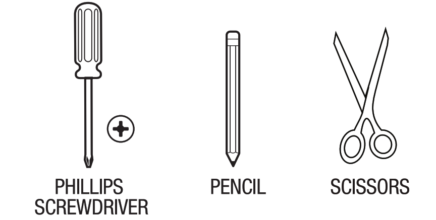
TOOLS REQUIRED
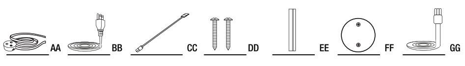
HARDWARE INCLUDED
![]() NOTE: Hardware not shown to actual size.
NOTE: Hardware not shown to actual size.
|
Part |
Description |
quantity |
| AA | LED Tape Light & Controller | 1 |
| BB | 6ft AC Cable | 1 |
| CC | 6in. Linkable Cable | 3 |
| DD | Mounting Screws | 2 |
| EE | Mounting Bracket | 1 |
| FF | Fixture Mounting Template | 1 |
| GG | 18in. Linkable Cable | 1 |
|
Item No. |
Description | Volts (V} | Wattage Per Fixture (W} | Input Current (mA) |
Maximum Linkable Units at 120V |
|
UCL192/FLEX/SCCT |
Flexible Under Cabinet LED Tape Light |
120 |
40 |
380 |
26 |
LED Fixture Installation
Position the Fixture
Find the desired place for the fixture and mark clearly using the provided mounting bracket template (FF).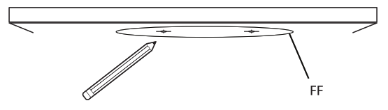
Installing the Mounting Bracket
Screw-in the Mounting Bracket (EE) using the Mounting Screws (DD) on the marked locations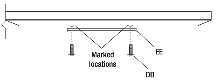
![]() NOTE: Make sure the LED tape light is aligned in the desired direction.
NOTE: Make sure the LED tape light is aligned in the desired direction.
Installing the Controller
Raise the Controller (BB) up and align the keyholes on the fixture to the Mounting Bracket (EE). Twist and lock the fixture into place by holding the fixture and gently rotating it in a counter-clockwise direction.
Cutting the Tape Light
Cut the Tape Light (AA) to the desired length at marked areas.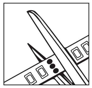
![]() NOTE: OnIy cut to length at the 3 dots marks on the tape light. Any other areas will permanently damage the strip. (ensure the power supply is not plugged in at the wall outlet).
NOTE: OnIy cut to length at the 3 dots marks on the tape light. Any other areas will permanently damage the strip. (ensure the power supply is not plugged in at the wall outlet).
Mounting the Tape Light
Remove the adhesive backing paper to expose the adhesive (see Fig.1) and fix the Tape Light (AA) to the desired position

![]() NOTE: Clean the area thoroughly (surface must be free of dust, dirt or grease).
NOTE: Clean the area thoroughly (surface must be free of dust, dirt or grease).
![]() NOTE: Avoid removing and relaying the Strip Light multiple times as the adhesive may wear off.
NOTE: Avoid removing and relaying the Strip Light multiple times as the adhesive may wear off.
Connecting the Power Supply
Plugin the power cord to the fixture.
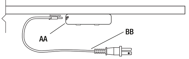
![]() NOTE: The plug in cord can be connected to either side of the fixture(AA).
NOTE: The plug in cord can be connected to either side of the fixture(AA).
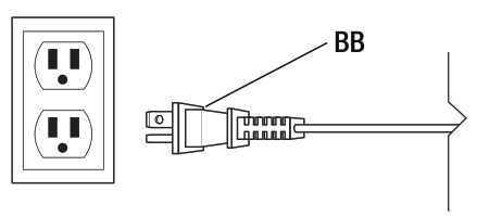
Connecting to a Power Outlet
The Tape Light can be Cut and Rejoined
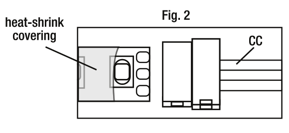
Removing the Heat-Shrink
- Remove 1cm of heat-shrink covering the connection points and install the linkable connector (CC) (see Fig. 2).
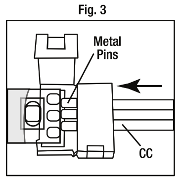
Adding the Connector
Open the end of the outer connector of the 6” connector (CC) and insert the end of the cut tape under the metal pins (see Fig. 3).
![]() NOTE: To install 2 or more LED fixtures, repeat the single failure installation instructions with two or more units.
NOTE: To install 2 or more LED fixtures, repeat the single failure installation instructions with two or more units.
Operating Instructions
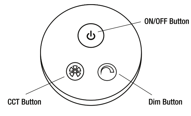
To select the desired dimming level, cycle through the dimming levels (High, Medium, Low, Dim, Off} by pressing the Dim Button. This setting will be fixed each time the 0N/OFF switch is turned 0N.
Changing the Color Temperature Setting
To select the desired color temperature, cycle through 2700K – 3000K – 3500K – 4000K – SOOOK by pressing the CCT Button. This setting will be fixed each time the ON/0FF switch is turned 0N.
This LED Fixture has the feature to operate and control multiple units, even if they are not linked.
To control multiple fixtures, Hold the CCT button for 3 seconds on all the fixtures to be controlled in a group. To remove the individual fixture from the group, Hold the CCT button on the fixture that you want to control individually for 3 seconds.
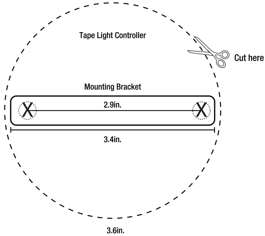
Mounting Guide
www.feit.complease contact 1-866-326-Bulb(2852)for further assistance
[xyz-ips snippet=”download-snippet”]