FEIT Electric LEDR56HOJBX/6WYCA Color Selectable LED
IMPORTANT SAFETY INSTRUCTIONS
Please read and understand this entire manual before attempting to assemble, operate or install this product. This product must be installed in accordance with any applicable installation code(s) by a qualified electrician or person familiar with the construction and operation of the product and the hazards involved.
- WARNING: RISK OF SHOCK. House electric current can cause painful shock or serious injury unless handled properly. For your safety, always remember to:
- A. Turn off the power supply at the fuse or circuit breaker box before you install the fixture.
- B. Ground the fixture to avoid potential electric shocks and to ensure reliable starting.
- C. Double-check all connections to be sure they are tight and correct.
- D. Wear rubber soled shoes and work on a sturdy ladder.
- This fixture is designed for use in a circuit protected by a fuse or circuit breaker. It is also designed to be installed in accordance with local electrical codes. If you are unsure about your wiring, consult a qualified electrician or a local electrical inspector and check your local electrical code.
- WARNING: RISK OF CUTS. Some metal parts in the fixture may have sharp edges. To prevent cuts and scrapes, wear gloves when handling the parts.
- Account for small parts and destroy packing material, as these may be hazardous to children.
NOTICE:
- All electrical connections must be in accordance with local and National Electrical Code (N.E.C) standards. If you are unfamiliar with proper electrical wiring connections, obtain the services of a qualified electrician.
- Remove the fixture and the mounting package from the box to make sure that no parts are missing by referencing the illustrations on the installation instructions.
- Turn off the main power at the circuit breaker before installing the fixture in order to prevent possible shock.
Supplier’s Declaration of Conformity:47 CFR § 2.1077 Compliance InformationResponsible Party:Feit Electric Company4901 Gregg Road,Pico Rivera, CA 90660, USA562-463-2852Unique Identifier:FEIT ITEM # LEDR56HOJBX/6WYCAThis device complies with part 15 of the FCC Rules. Operation is subject to the following two conditions: (1) This device may not cause harmful interference, and (2) this device must accept any interference received, including interference that may cause undesired operation. Note: This equipment has been tested and found to comply with the limits for a Class B digital device, pursuant to part 15 of the FCC Rules. These limits are designed to provide reasonable protection against harmful interference in a residential installation. This equipment generates, uses and can radiate radio frequency energy and, if not installed and used in accordance with the instructions, may cause harmful interference to radio communications. However, there is no guarantee that interference will not occur in a particular installation. If this equipment does cause harmful interference to radio or television reception, which can be determined by turning the equipment off and on, the user is encouraged to try to correct the interference by one or more of the following measures: Reorient or relocate the receiving antenna. Increase the separation between the equipment and receiver. Connect the equipment into an outlet on a circuit different from that to which the receiver is connected. Consult the dealer or an experienced radio/TV technician for help. Any changes or modifications not expressly approved by the manufacturer could void the user’s authority to operate the equipment.
WARRANTY
This product is warrantied to be free from defects in workmanship and materials for up to five years from date of purchase. If the product fails within the warranty period, please contact Feit Electric at [email protected], visit feit.com/contact-us or call 1-866-326-BULB (2852) for instructions on replacement or refund. REPLACEMENT OR REFUND IS YOUR SOLE REMEDY. EXCEPT TO THE EXTENT PROHIBITED BY APPLICABLE LAW, ANY IMPLIED WARRANTIES ARE LIMITED IN DURATION TO THE DURATION OF THIS WARRANTY. LIABILITY FOR INCIDENTAL OR CONSEQUENTIAL DAMAGES IS HEREBY EXPRESSLY EXCLUDED. Some states and provinces do not allow the exclusion of incidental or consequential damages, so the above limitation or exclusion may not apply to you. This warranty gives you specific legal rights, and you may also have other rights which vary from state to state or province to province.
PACKAGE CONTENTS
Before beginning installation of this product, make sure all parts are present. Compare parts with package contents list and diagram. If any part is missing or damaged, do not attempt to assemble, install or operate this product.
| COMPONENTS INCLUDED | |
| A | (1) POWER SUPPLY BOX |
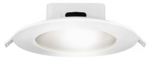
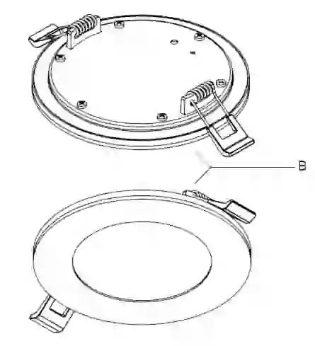
| B | (1) RECESSED DOWNLIGHT |
| C | (3) TERMINAL BLOCK CONNECTORS |
| D | (1) INSTRUCTION MANUAL |
| E | (2) SCREWS (M4*25mm) |
PRODUCT ELECTRICAL RATINGS
120 V / 60 Hz, XX mA, 17 W
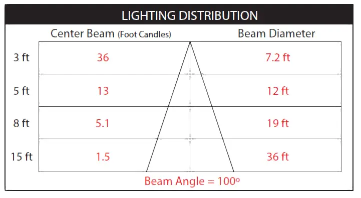
SUITABLE FOR WET LOCATIONS.The foam insert between the trim and ceiling of this panel will create an air tight seal and is required for the ASTM Air Tight Certification. Suitable for Type IC or non-IC.Continuous dimming between 5% – 100% with most dimmers.
HOW TO SELECT YOUR LIGHT COLOR
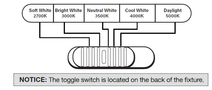
PICK YOUR FAVORITE LIGHT COLOR BEFORE INSTALLING
- You can lock in one color temperature or change among multiple color temperatures, it will memorize the last color temperature and reset automatically.
- When the slide switch is set to SW (Soft White), the color temperature is set at 2700K.
- When the slide switch is set to BW (Bright White), the color temperature is set at 3000K.
- When the slide switch is set to NW (Neutral White), the color temperature is set at 3500K.
- When the slide switch is set to CW (Cool White), the color temperature is set at 4000K.
- When the slide switch is set to DL (Daylight), the color temperature is set at 5000K.
HOW TO SWITCH TO NIGHTLIGHT MODE
- Toggle the wall switch to power on the light.
- At initial light up, the product is set to downlight mode.
- To transition to nightlight mode, toggle the wall switch off and back on within 2 seconds.
- To transition back to downlight mode, toggle the wall switch off and back on within 2 seconds
PRE-INSTALLATION REVIEW
- Turn the power OFF from the breaker panel before starting installation.
- Locate a suitable location for the fixture and cut the correctly sized hole in the drywall or ceiling tile (for a suspended T-Bar type ceiling) – refer to Hole Cut Out Template for appropriate size.
- Know the location of your joist before making any cuts.
- Run electrical wire from the switch (power supply) through the mounting hole; use NM cable or Flexible 2Metal Conduit Cable.
- Use the slide switch to choose a preferred color temperature before installing (2700K, 3000K, 3500K, 4000K, 5000K)
INSTALLATION INSTRUCTIONS FOR RECESSED HOUSING
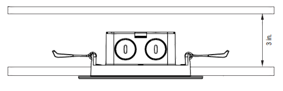
- Ensure the space above the installed fixture is at least 3 in.

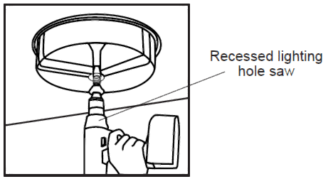
- Cut a 6 1/2 in. hole in the ceiling as round as possible using the template provided and a recessed lighting hole saw.NOTE: Before cutting, ensure that the hole does not impinge on joists, pipe work, cable or other building services.
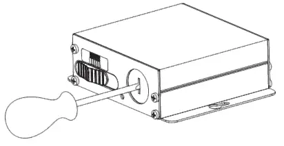
- Carefully remove the knock-out with a screw driver or punch.
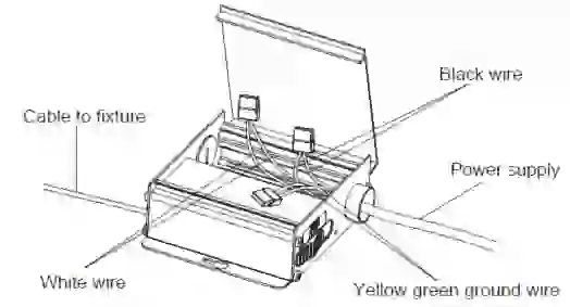
- Open the power supply box cover. Feed the supply wire into the knockout hole using a 1/2 in. clamp connector (not included) and make all the connections inside the power supply box using wago connectors. Connect the 120V line (black) wire to the black wire. Connect the neutral (white) wire to the white wire. Connect the ground (green) wire to the green wire. This power supply box needs to be grounded.
- After connecting the wires correctly, place the wires inside the power supply box and close the box properly.
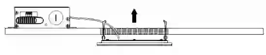
- Hold the spring clips against the fixture and gently guide into the ceiling until the clips snap into place. The fixture should be flush with the ceiling.NOTE: Ceiling thickness must be 1/2 in. to 3/4 in.
- Restore the power at the breaker panel.
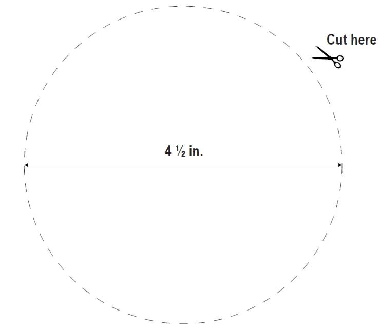
CUT OUT TEMPLATE – For a 6 1/2 in. hole.
 report this ad
![]()
References
[xyz-ips snippet=”download-snippet”]