![]()
![]()
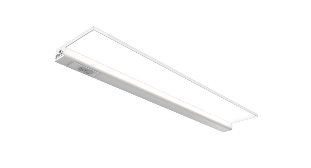
FLAT-PANEL UNDER CABINET LIGHTFITS 24 IN. CABINETS (20 1/2 IN. TOTAL LENGTH)IMPORTANT SAFETY INSTRUCTIONS AND INSTALLATION GUIDE
READ BEFORE INSTALLATION SAVE THESE INSTRUCTIONSQuestions, problems, missing parts? Before returning to the store, call Feit Electric Customer Service 8 a.m. – 5 p.m., PST, Monday – Friday1-866-326-BULB (2852)FEIT.COM
We appreciate the trust and confidence you have placed in Feit Electric through the purchase of this Under Cabinet Light. We strive to continually create quality products designed to enhance your home. Visit us online to see our full line of products available for your home improvement needs. Thank you for choosing Feit Electric.
Safety Information
IMPORTANT SAFEGUARDS: ALWAYS FOLLOW BASIC SAFETY PRECAUTIONS WHEN USING ELECTRICAL PRODUCTS, ESPECIALLY WHEN CHILDREN ARE PRESENT.
Save These Instructions
![]() CAUTION: Do not install this fixture inside a totally enclosed cabinet. Do not mount over stoves.
CAUTION: Do not install this fixture inside a totally enclosed cabinet. Do not mount over stoves.
![]() WARNING: To avoid the risk of electrical shock, always make sure the product is unplugged from the electrical outlet before assembling, disassembling, relocating, servicing or cleaning it.
WARNING: To avoid the risk of electrical shock, always make sure the product is unplugged from the electrical outlet before assembling, disassembling, relocating, servicing or cleaning it.![]() CAUTION: Do not install this product in a wet location.
CAUTION: Do not install this product in a wet location.![]() CAUTION: Do not install this product in an outdoor location.
CAUTION: Do not install this product in an outdoor location.![]() CAUTION: Do not use chemical solvents or harsh abrasives to clean the fixture.Supplier’s Declaration of Conformity: 47 CFR § 2.1077 Compliance Information
CAUTION: Do not use chemical solvents or harsh abrasives to clean the fixture.Supplier’s Declaration of Conformity: 47 CFR § 2.1077 Compliance Information
Responsible Party: Feit Electric Company4901 Gregg Road, Pico Rivera, CA 90660, USA562-463-2852Unique Identifier: UCL24FP/5CCTCAG2
FCC STATEMENT
This device complies with part 15 of the FCC Rules. Operation is subject to the following two conditions: (1) This device may not cause harmful interference, and (2) this device must accept any interference received, including interference that may cause undesired operation. Note: This equipment has been tested and found to comply with the limits for a Class B digital device, pursuant to part 15 of the FCC Rules. These limits are designed to provide reasonable protection against harmful interference in a residential installation. This equipment generates, uses, and can radiate radio frequency energy and, if not installed and used in accordance with the instructions, may cause harmful interference to radio communications. However, there is no guarantee that interference will not occur in a particular installation. If this equipment does cause harmful interference to radio or television reception, which can be determined by turning the equipment off and on, the user is encouraged to try to correct the interference by one or more of the following measures: Reorient or relocate the receiving antenna. Increase the separation between the equipment and receiver. Connect the equipment into an outlet on a circuit different from that to which the receiver is connected. Consult the dealer or an experienced radio/TV technician for help. Any changes or modifications not expressly approved by the manufacturer could void the user’s authority to operate the equipment. CAN ICES-005(B).
Limited Warranty
This product is warranted to be free from defects in workmanship and materials for up to 5 years from date of purchase. If the product fails within the warranty period, please contact Feit Electric at [email protected], visit feit.com/contact-us or call 1-866-326-BULB (2852) for instructions on replacement or refund. REPLACEMENT OR REFUND IS YOUR SOLE REMEDY. EXCEPT TO THE EXTENT PROHIBITED BY APPLICABLE LAW, ANY IMPLIED WARRANTIES ARE LIMITED IN DURATION TO THE DURATION OF THIS WARRANTY. LIABILITY FOR INCIDENTAL OR CONSEQUENTIAL DAMAGES IS HEREBY EXPRESSLY EXCLUDED. Some states and provinces do not allow the exclusion of incidental or consequential damages, so the above limitation or exclusion may not apply to you. This warranty gives you specific legal rights, and you may also have other rights which vary from state to state or province to province.
Pre- Assembly
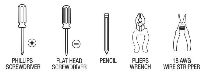
TOOLS REQUIRED
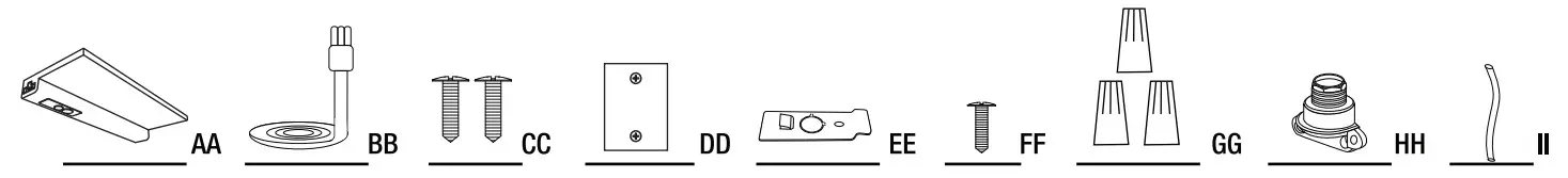
HARDWARE INCLUDED
![]() NOTE: Hardware not shown to actual size.
NOTE: Hardware not shown to actual size.
| Part | Description | Quantity |
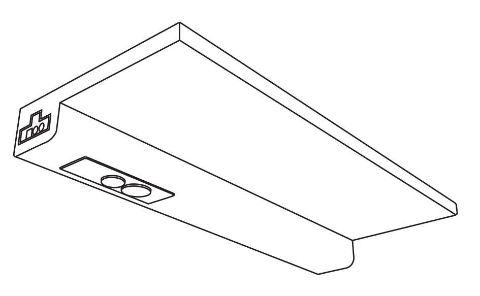
| AA | 24 in. LED Flat Panel Fixture | 1 |
| BB | 18 in. Linking Cable | 1 |
| CC | Mounting Screws | 2 |
| DD | Fixture Mounting Template | 1 |
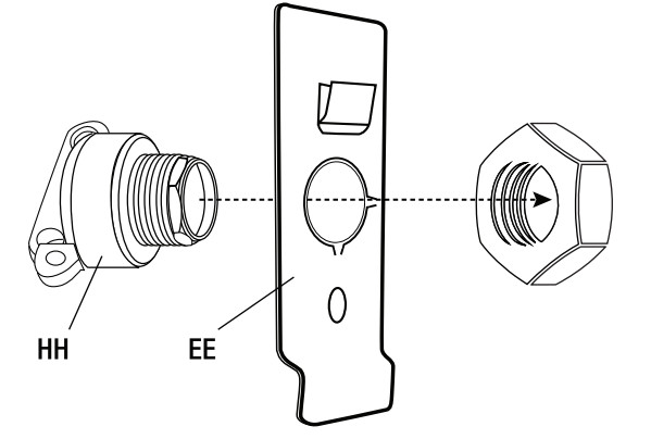
| EE | Hardwire Bracket | 1 |
| FF | Hardwire Bracket Screw | 1 |
| GG | Wire Nut | 3 |
| HH | Clamp Connector | 1 |
| II | 18 AWG Wire (Green Ground Wire) | 1 |
| Rem No. | Description | Volts (V) | WattagePer Fixture (W) | InputCurrent (mA) | Maximum LinkableUnits at 120V | Maximum LinkableUnits withIn-Wall Dimmer |
| UCL24FP/5CCTCAG2 | 24 Inch Flat PanelUnder Cabinet LED Fixture | 120 | 20 | 240 | 41 | 5 |
| Distance | Center Beam (Foot Candles) | Beam Diameter |
| 3 ft5 ft8 h15ft | 67249.42.7 | 7.2 ft12 ft19 ft36 fy |
| Beam Spread:100* | : 603 |
Single LED Fixture Hardwire Installation I
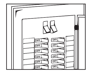
- Turn Off the PowerTurn the power OFF from the breaker panel before starting installation.

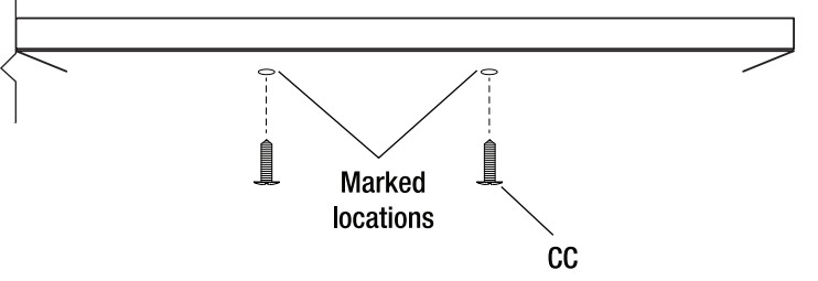
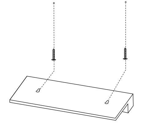
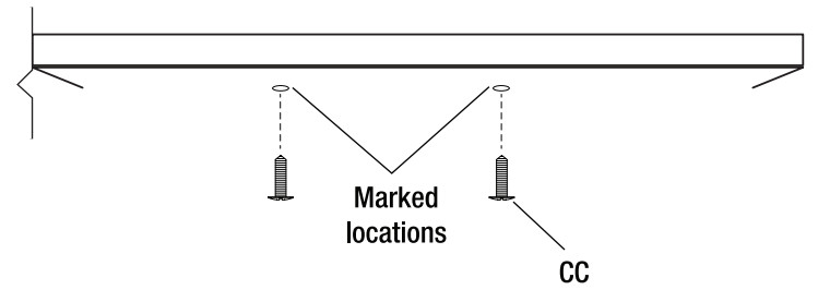
- Position the FixtureFind the desired place for the LED light fixture and mark dearly using the provided mounting bracket template (DD).
- Installing the Mounting ScrewsScrew-in the Mounting Screws (CC) on the marked locations, leaving a gap of 0.08-0.10 inches between the screw head and the installation surface.
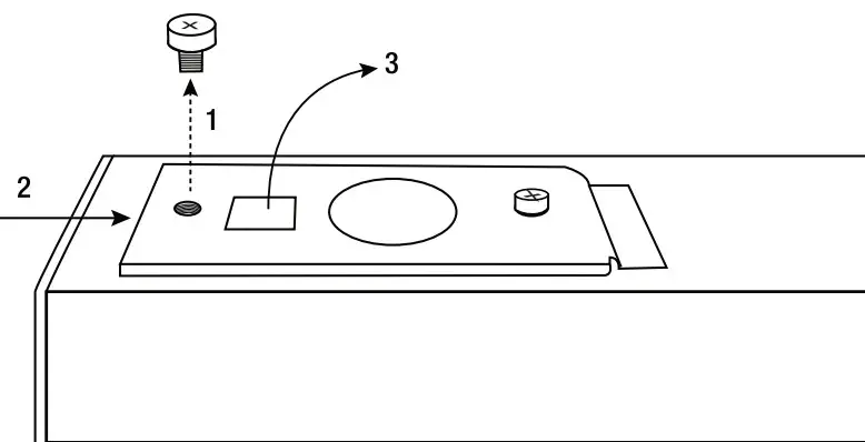
- Removing the HardwireBracket Remove the screw on the hardwire bracket, then slide and lift the bracket off of the fixture.
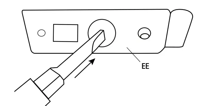
- Removing the Knock-outCarefully remove the knock-out with a flathead screwdriver.
- Installing the Clamp Connector to the KnockoutHole Install the Clamp Connector (HH) to the knock-out hole by inserting it through the hole and securing it with the nut The Clamp Connector (HH) should be on the outer side of the bracket.
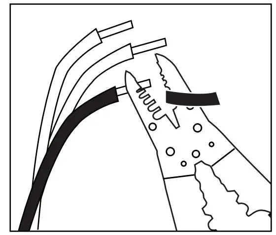
- Cutting and Stripping WiresTake out of the black and white 18 AWG wires in the fixture CC and the green 18 AWG wire (IQ in the plastic bag. Cut and strip the wires to the correct length.
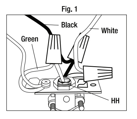
- Wire Power Supply to the FixtureFeed the supply wire through the Clamp Connector (HH) and knockout hole and make all connections using the wire nuts provided. Connect the 120V line (black) wire to the black wire. Connect the neutral (white) wire to the white wire. Connect the ground (green) wire to the green wire.
- Replace the Wiring BracketAfter connecting the wires correctly, place the wires inside the fixture and reinsert the bracket, sliding it over and screwing it securely.
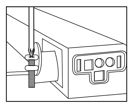
- Secure Supply Wires with the ClampConnector Secure the supply wire by firmly screwing the clamp connectors down on the wire.
- Installing LED FixtureAlign holes on the back of the fixture to the heads of the Mounting Screws. Slide fixture towards the mounting slot If the fixture is not snug, remove the fixture and readjust the screws.
- Linking LED FixturesConnect the LED Fixtures (AA) using the provided Linking Cable (BB). NOTE: To install 2 or more LED fixtures, repeat the single fixture installation instructions with two or more units.


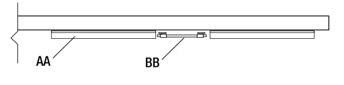
 NOTE: To install 2 or more LED fixtures, repeat the single fixture installation instructions with two or more units.
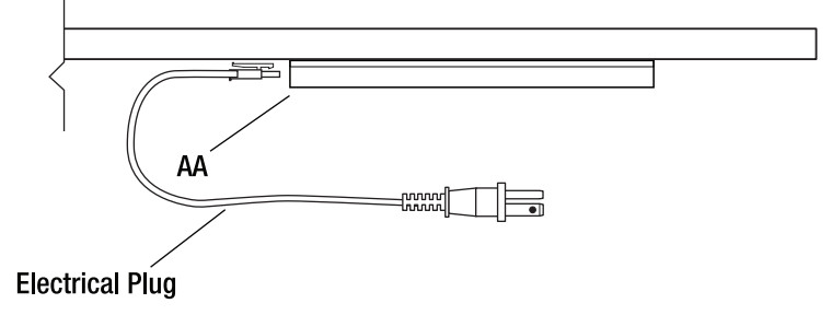
Alternative Plug-In Installation (Electrical Plug not Included)
- Position the FixturesFind the desired place for the LED light fixture and mark clearly using the provided mounting bracket template (DD).
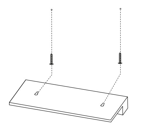
- Installing the MountingScrews Screw in the Mounting Screws (CC) on the marked locations, leaving a gap of 0.08-0.10 inches between the screw head and the installation surface.
- Installing LED FixtureAlign holes on the back of the fixture to the heads of the Mounting Screws. Slide fixture forwards to secure into place. If the fixture is not snug, remove the fixture and readjust the screws.
- Connecting the Power SupplyPlug-In Electrical Plug to the LED Fixture (AA). NOTE: The °teethesl plug can be connected to either side of the LED Fixture (AA).
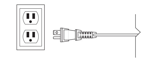
- Connecting to a PowerOutlet Connect the Electrical Plug to the power outlet on the wall.
Operating Instructions
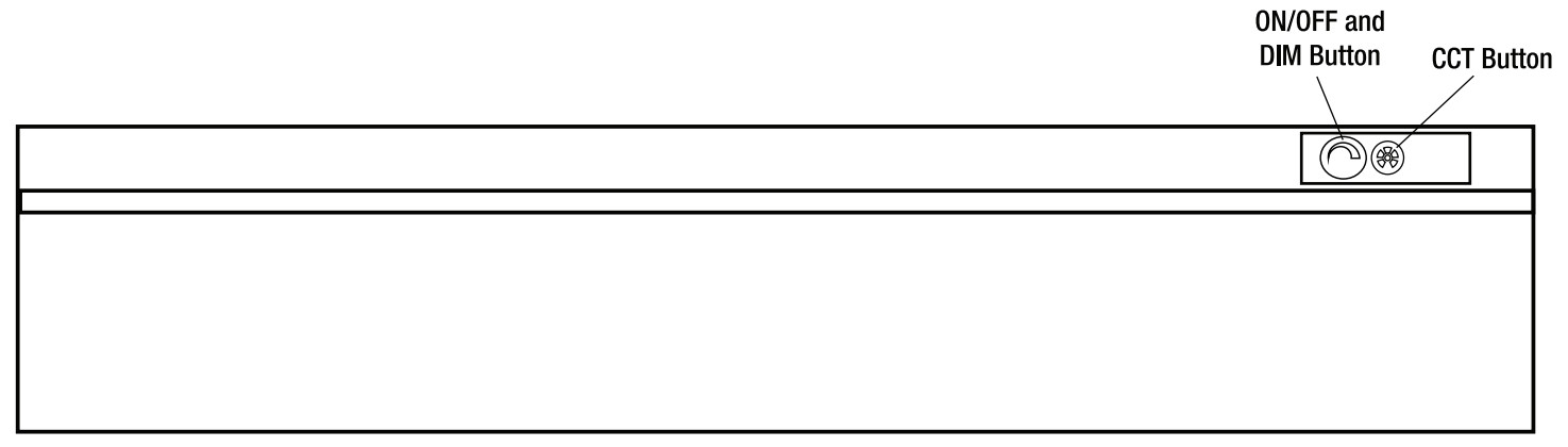
Use the ON/OFF and Dim Button for ON/OFF Operation and to Change the Dimming Levels
- To select the desired dimming level, cycle through the dimming levels (High, Medium, Low, Dim, Off) by pressing the Dim Button. This setting will be fixed each time the ON/OFF switch is turned ON.
Changing the Color Temperature Setting
- To select the desired color temperature, cycle through 2700K – 3000K – 3500K – 4000K – 5000K by pressing the CCT Button. This setting will be fixed each time the ON/OFF switch is turned ON.
This LED Fixture has the feature to operate and control multiple units, even if they are not linked.
- To control multiple fixtures, Hold the CCT button for 3 seconds on all the fixtures to be controlled in a group.
- To remove the individual fixture from the group, Hold the CCT button on the fixture that you want to control individually for 3 seconds.
WWW.FEIT.COMPlease contact 1-866-326-BULB (2852) for further assistance.
[xyz-ips snippet=”download-snippet”]