
OPERATING MANUALFIBARO MOTION SENSORFGMS-001
Important safety information
Read this manual before attempting to install the device!Failure to observe recommendations included in this manual may be dangerous or cause a violation of the law. The manufacturer, Fibar Group S.A. will not be held responsible for any loss or damage resulting from not following the instructions of the operating manual. The alarm functionality of devices is an additional feature increasing the comfort level of your home automation system. If you want to use a professional security service, please contact them to determine what systems can provide protection of your estate.Compliance with safety standards:The device is designed to be used in Z-Wave home automation systems (e.g. FIBARO) and is compliant with IEC/UL/CSA 60950-1. In case of the integration with another system, e.g. alarm system, it is required to verify the compliance with additional standards.
General information about the FIBARO System
FIBARO is a wireless smart home automation system, based on the Z-Wave protocol. All of the available devices can be controlled through a computer (PC or Mac), smartphone, or tablet. Z-Wave devices are not only receivers but can also repeat the signal, increasing the Z-Wave network’s range. It gives an advantage over traditional wireless systems that require a direct link between transmitter and receiver, as a result, the construction of the building could affect the network’s range negatively.Every Z-Wave network has its unique identification number (home ID). Multiple independent networks can exist in the building without interfering. The transmission security of the FIBARO System is comparable to wired systems.Z-Wave technology is the leading solution in smart home automation. There is a wide range of Z-Wave devices that are mutually compatible, independently of the manufacturer. It gives the system the ability to evolve and expand over time. For more information visit www.fibaro.com.
Description and features
FIBARO Motion Sensor is a universal Z-Wave multi-sensor. Along with detecting motion the device measures the temperature and light intensity. The sensor has a built-in accelerometer to detect any tampering of the device. FIBARO Motion Sensor is battery powered device and designed to be installed quickly and easily on any surface.The LED indicator signals motion, temperature level, operating mode and can be used to see if the device is within the Z-Wave network. The motion sensor can be used for lighting scenes and presence monitoring systems.
Main features of FIBARO Motion Sensor:
- compatible with any Z-Wave or Z-Wave Plus Controller
- supports protected mode (Z-Wave network security mode) with AES128 encryption
- detects motion using a passive IR sensor
- measures ambient temperature
- measures light intensity
- detects vibrations
- extremely easy installation
- maybe installed anywhere – wall or any surface
- battery-powered
- theft and tampering protection – once vibrations are detected, the notification is sent to the main controller
- detected movement, temperature, and vibrations are signaled by the built-in LED diode
 FIBARO Motion Sensor is a fully compatible Z-Wave Plus device.
![]() NOTEThis device may be used with all devices certified with the Z-Wave Plus certificate and should be compatible with such devices produced by other manufacturers.
NOTEThis device may be used with all devices certified with the Z-Wave Plus certificate and should be compatible with such devices produced by other manufacturers.![]() NOTEFIBARO Motion Sensor is a Security Enabled Z-Wave Plus product and a Security Enabled Z-Wave Controller must be used in order to fully utilize the product.
NOTEFIBARO Motion Sensor is a Security Enabled Z-Wave Plus product and a Security Enabled Z-Wave Controller must be used in order to fully utilize the product.
Basic activation
- Turn the cover counter-clockwise and open it.

- Remove the battery blocker.
- Add the device (see “Adding/removing the device” on page 5).
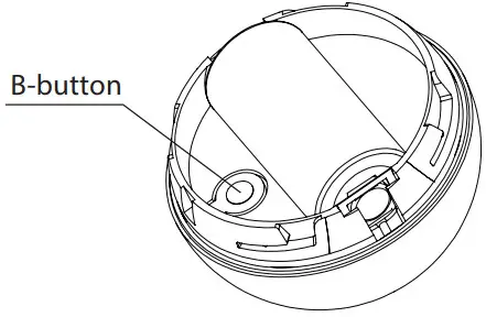
- Wake up the sensor by triple-clicking the B-button.
- Close the cover and turn it clockwise.
- Install the device (see “Physical installation” on page 6).
Adding/removing the device
Adding (Inclusion) – Z-Wave device learning mode, allowing to add the device to the existing Z-Wave network.To add the device to the Z-Wave network:
- Open the cover.
- Place the Motion Sensor within the direct range of your Z-Wave controller.
- Set the main controller in (security/non-security) add mode (see the controller’s manual).
- Quickly, three times press the B-button.
- Wait for the adding process to end.
- Successful adding will be confirmed by the Z-Wave controller’s message.
Removing (Exclusion) – Z-Wave device learning mode, allowing to remove the device from the existing Z-Wave network.To remove the device from the Z-Wave network:
- Open the cover.
- Place the Motion Sensor within the direct range of your Z-Wave controller.
- Set the main controller in remove mode (see the controller’s manual).
- Quickly, three times press the B-button.
- Wait for the removing process to end.
- Successful removal will be confirmed by the Z-Wave controller’s message.
![]() NOTEAdding in security mode must be performed up to 2 meters from the controller.
NOTEAdding in security mode must be performed up to 2 meters from the controller.![]() NOTEIn case the Sensor is not added, please reset the Sensor and repeat the adding procedure.
NOTEIn case the Sensor is not added, please reset the Sensor and repeat the adding procedure.![]() NOTERemoving the device from the Z-Wave network restores all the default parameters of the device.
NOTERemoving the device from the Z-Wave network restores all the default parameters of the device.
Physical installation
Detection range:The detection range of the Motion Sensor is shown below. The actual range of the Sensor can be influenced by environmental conditions.
Installation location and working conditions:The Motion Sensor should be installed in a corner of the room or perpendicularly to the doors.Moving objects such as trees blowing in the wind, cars passing by, windmills, and moving masses of air and heat within the detection area of the sensor can cause false motion detection.

Installing the Motion Sensor:
- Install the holder (using an expansion bolt or a sticker).
- Insert the device into the holder.
- Test the operation – check whether the device indicates motion detection.
NOTERemember to add the device to the Z-Wave network prior to installation, as the adding procedure must be performed within the direct range of the controller.
Operating the device
Controlling the Motion Sensor using the B-button:The Motion Sensor is equipped with a B-button, which allows to use the menu and additionally perform the following actions:1x click: wake up the device or select the desired menu option (ifthe menu is active)3x click: add/remove the device to/from a Z-Wave networkHolding: enter/navigate through the menuVisual indications:The Motion Sensor is equipped with a LED diode, signaling the sensor’s operating modes and alarms. In addition, the visual indicator may inform of the Z-Wave network range and the current temperature.visual indicator signaling modes:
- Motion Alarm color will vary depending on the temperature. The color and the signaling mode can be set in parameter 80.
- Tamper alarm is signaled with an alternating blinking in LAPD colors (red – blue – white).
- The Z-Wave node Info command frame is signaled with glowing in blue. node Info command frame is sent each time the device wakes up.
- The menu position is signaled with the assigned illumination color.
Menu:The menu allows performing Z-Wave network actions. In order to use the menu:
- Press and hold the B-button.
- Wait for the device to indicate the desired position with a color:• VIOLET – Z-Wave network’s range test• YELLOW – device reset
- Release the B-button.
- Click the B-button to confirm the selection.
Waking up the Motion Sensor:The Motion Sensor needs to be woken up to receive information on new configurations from the controller, like parameters and associations. To wake up the sensor manually triple-click the B-button located inside the housing.Controlling the Motion Sensor with FIBARO Home Center controller:The Motion Sensor has a built-in motion detector, temperature sensor, and light intensity sensor, which make it a multi-channel device. In the home, the Center interface will be presented as three devices.
Seismograph mode:The Motion Sensor can be configured to work as a simple earthquake detector, by setting the parameter 24 value to 1. Reports with the scale of the vibrations (in the Modified Mercalli Scale) will be sent immediately after vibrations have been detected. The minimal power of vibrations that will be reported, can be set in parameter 20. Once the vibrations cease and the time of sustaining alarm elapses, reports will be stopped.
Orientation in space:The Motion Sensor has a built-in accelerometer. When parameter 24 is set to 2, the Z-Wave network controller will be informed of the Sensor’s orientation in space by sending a report after triggering the tamper alarm.
Resetting the Motion Sensor:The reset procedure erases the memory, including all information on the Z-Wave network and the main controller.
- Open the cover.
- Press and hold the B-button.
- Wait for the visual indicator to glow yellow (2nd menu position).
- Release the B-button.
- Click the B-button to confirm the selection.
- After a few seconds, the device will be reset, which is signaled with the red, fading visual indicator color.
Notification report:The device uses notification Command Class to report different events.
| notification Type | Event |
| home Security | Tampering, product covering removed |
| home Security | Motion Detection, unknown location |
![]() NOTEResetting the device is not the recommended way of removing the device from the the-Wave network. Use reset procedure only if the primary controller is missing or inoperable. Certain device removal can be achieved by the procedure of removing described in “Adding/removing the device” on page 6.
NOTEResetting the device is not the recommended way of removing the device from the the-Wave network. Use reset procedure only if the primary controller is missing or inoperable. Certain device removal can be achieved by the procedure of removing described in “Adding/removing the device” on page 6.![]() NOTECommand Class Basic value is related to the status of the motion sensor (0x00 – no motion, 0xFF – motion detected).
NOTECommand Class Basic value is related to the status of the motion sensor (0x00 – no motion, 0xFF – motion detected).
Association
Association (linking devices) – direct control of other devices within the Z-Wave system network e.g. Dimmer, Relay Switch, Roller Shutter, or scene (may be controlled only through a Z-Wave controller).The Motion Sensor provides the association of five groups:1st association group – “Lifeline” reports the device status and allows for assigning a single device only (main controller by default).2nd association group – “Motion” is assigned to the motion sensor – sends Basic Set command frames to the associated devices.3rd association group – “Tamper” is assigned to the tamper – sends tamper alarm and alarm cancellation frames to the associated devices.4th association group – “Motion BC” is assigned to the motion sensor – sends motion detection and alarm cancellation frames to the associated devices.Provides backward compatibility with controllers not supporting Z-Wave Plus protocol.5th association group – “Tamper BC” is assigned to the tamper – sends tamper alarm and alarm cancellation frames to the associated devices. Provides backward compatibility with controllers not supporting Z-Wave Plus protocol.The Motion Sensor in the 2nd to 5th group allows controlling 5 regular and 5 multichannel devices per association group, with the exception of “LifeLine” that is reserved solely for the controller, and hence only 1 node can be assigned.It is not recommended to associate more than 10 devices in general, as the response time to control commands depends on the number of associated devices. In extreme cases, system response may be delayed.To add an association (using the Home Center controller):
- Go to device options by clicking the icon:
- Select the „Advanced” tab.
- Specify to which group and what devices are to be associated.
- Wait for the configuration process to end. Sending relevant information to devices added to associated groups may take even a few minutes.
- Wake up the device manually to speed up the configuration process.

![]() NOTEAssociation allows direct transfer of control commands between devices is performed without the participation of the main controller and requires associated device to be in direct range.
NOTEAssociation allows direct transfer of control commands between devices is performed without the participation of the main controller and requires associated device to be in direct range.
Z-Wave range test
The Motion Sensor has a built-in Z-Wave network main controller’s range tester.
Follow the below instructions to test the main controller’s range:
- Open the cover.
- Press and hold the B-button.
- Wait for the visual indicator to glow violet (1st menu position).
- Release the B-button.
- Click the B-button to confirm the selection.
- visual indicator will indicate the Z-Wave network’s range (range signalling modes described below).
- To exit the Z-Wave range test, press the B-button briefly.
Z-Wave range tester signaling modes:Visual indicator pulsing green – the Motion Sensor attempts to establish direct communication with the main controller. If a direct communication attempt fails, the device will try to establish a routed communication, through other modules, which will be signaled by a visual indicator pulsing yellow.Visual indicator glowing green – the Motion Sensor communicates with the main controller directly.Visual indicator pulsing yellow – the Motion Sensor tries to establish a routed communication with the main controller through other modules (repeaters).Visual indicator glowing yellow – the Motion Sensor communicates with the main controller through the other modules. After 2 seconds the device will retry to establish direct communication with the main controller, which will be signaled with a visual indicator pulsing green.Visual indicator pulsing violet – the Motion Sensor does communicate at the maximum distance of the Z-Wave network. If the connection proves successful it will be confirmed with a yellow glow. It’s not recommended to use the device at the range limit.visual indicator glowing red – the Motion Sensor is not able to connect to the main controller directly or through another Z-Wave network device (repeater).
![]() CAUTIONTo make the Z-Wave range test possible, the device must be added to the Z-Wave controller. Testing may stress the network, so it is recommended to perform the test only in special cases.
CAUTIONTo make the Z-Wave range test possible, the device must be added to the Z-Wave controller. Testing may stress the network, so it is recommended to perform the test only in special cases.![]() NOTEThe communication mode of the Motion Sensor may switch between direct and one using routing, especially if the device is on the limit of the direct range.
NOTEThe communication mode of the Motion Sensor may switch between direct and one using routing, especially if the device is on the limit of the direct range.
Advanced parameters
The Motion Sensor allows customizing its operation to the user’s needs. The settings are available in the FIBARO interface as simple options that may be chosen by selecting the appropriate box.In order to configure the Motion Sensor (using the Home Center controller):
- Go to the device options by clicking the icon:
- Select the „Advanced” tab.
Wake up intervalAvailable settings: 1-65535 (1-65535 seconds)Default setting: 7200 (every 2 hours)The Motion Sensor will wake up after each defined time interval and always try to connect with the main controller. After a successful communication attempt, the sensor will update configuration parameters, associations, and settings and will go into standby mode. After failed communication attempt (e.g. lack of Z-Wave range) the device will go into standby mode and retry to establish a connection with the main controller after the next time interval.Wake up may perform manually by a single B-button click.A longer time interval means less frequent communication and thus longer battery life.
1. Motion detection – sensitivityThe lower the value, the more sensitive the PIR sensor is.
| Available settings: | 8-255 | ||
| Default setting: | 15 | Parameter size: | 2 [bytes] |
![]() NOTEBlind time should be shorter that the time period set in parameter 6 (alarm cancellation delay).
NOTEBlind time should be shorter that the time period set in parameter 6 (alarm cancellation delay).
2. Motion detection – blind timePIR sensor is “blind” (insensitive) to motion after the last detection for the amount of time specified in this parameter.Shorter time periods allow detection motion more frequently, but the battery will be drained faster.
| Available settings: | 0-15 (0.5-8 seconds, time [s] = 0.5 x (value+1)) | ||
| Default setting: | 15 | Parameter size: | 1 [byte] |
![]() NOTEBlind time should be shorter than the time the period set in parameter 6 (alarm cancellation delay).
NOTEBlind time should be shorter than the time the period set in parameter 6 (alarm cancellation delay).
3. Motion detection – pulse counterThis parameter determines the number of moves required for the PIR sensor to report motion. The higher the value, the less sensitive the PIR sensor is. It is not recommended to modify this parameter setting!
| Available settings: | 0 – 1 pulse1 – 2 pulses2 – 3 pulses3 – 4 pulses | ||
| Default setting: | 1 (2 pulses) | Parameter size: | 1 [byte] |
4. Motion detection – window timePeriod of time during which the number of moves set in parameter 3 must be detected in order for the PIR sensor to report motion. The higher the value, the more sensitive the PIR sensor is. It is not recommended to modify this parameter setting!
| Available settings: | 0 – 4 seconds1 – 8 seconds2 – 12 seconds3 – 16 seconds | ||
| Default setting: | 2 (12 seconds) | Parameter size: | 1 [byte] |
6. Motion detection – alarm cancellation delayThe time period after which the motion alarm will be canceled in the main controller and associated devices. Any motion detected during this period resets the timer.
| Available settings: | 1-32767 (in seconds) | ||
| Default setting: | 30 (the 30s) | Parameter size: | 2 [bytes] |
7. Motion detection – operating modeThis parameter determines in which part of the day the PIR sensor will be active.This parameter influences only the motion reports and associations. Tamper, light intensity, and temperature measurements will be still active, regardless of these parameter settings.
| Available settings: | 0 – PIR sensor always active1 – PIR sensor active during the day only2 – PIR sensor active during the night only | ||
| Default setting: | 0 | Parameter size: | 1 [byte] |
8. Motion detection – night/dayThis parameter defines the difference between night and day in terms of light intensity, used in parameter 8.
| Available settings: | 1-32767 (1-32767 lux) | ||
| Default setting: | 200 (200 lux) | Parameter size: | 2 [bytes] |
![]() NOTEvalues of BASIC On and BASIC OFF command frames can e modified with dedicated parameters (14 and 16).
NOTEvalues of BASIC On and BASIC OFF command frames can e modified with dedicated parameters (14 and 16).
9. BASIC command class configurationThis parameter determines the command frames sent to the 2nd association group (assigned to the PIR sensor).
| Available settings: | 0 – BASIC On and OFF command frames sent in Basic Command Class1 – only the BASIC On command frame sent in Basic Command Class2 – only the BASIC OFF command frame sent in Basic Command Class | ||
| Default setting: | 0 | Parameter size: | 1 [bytes] |
10. BASIC ON command frame valueThe command frame is sent at the moment of motion detection. Further motion detections, during the cancellation time, will not result in sending the association.
| Available settings: | 0-255 | ||
| Default setting: | 255 | Parameter size: | 2 [bytes] |
11. BASIC OFF command frame valueThe command frame is sent at the moment of motion alarm cancellation, after the cancellation delay time specified in parameter 6.
| Available settings: | 0-255 | ||
| Default setting: | 0 | Parameter size: | 2 [bytes] |
12. Associations in Z-Wave network Security ModeThis parameter defines how commands are sent in a specified association group: secure or non-secure. The parameter is active only in Z-Wave network security mode. It does apply to 1st group “Lifeline”.
| Available settings: | 0 – none of the groups sent as secure1 – 2nd group sent as secure2 – 3rd group sent as secure4 – 4th group sent as secure8 – 5th group sent as secure | ||
| Default setting: | 15 | Parameter size: | 1 [bytes] |
![]() NOTEvalues of BASIC On and BASIC OFF command frames can be modified with dedicated parameters (14and 16).
NOTEvalues of BASIC On and BASIC OFF command frames can be modified with dedicated parameters (14and 16).
13. Tamper – sensitivityThis parameter determines the change in force acting on the device, which will result in reporting tamper alarm – g-force acceleration.
| Available settings: | 0 – tamper inactive1-121 – (0.08-2g; every 0.016g) | ||
| Default setting: | 20 (0.4g) | Parameter size: | 1 [bytes] |
14. Tamper – alarm cancellation delayThe time period after which a tamper alarm will be canceled in the main controller and associated devices. Any tampering detected during this period will not extend the delay.
| Available settings: | 1-32767 (in seconds) | ||
| Default setting: | 30 (the 30s) | Parameter size: | 2 [bytes] |
15. Tamper – operating modesThis parameter determines the function of the tamper and sent reports. It is an advanced feature serving much more functions than just detection of tampering.
| Available settings: | 0 – tamper only1 – tamper and earthquake detector2 – tamper and orientation in space | ||
| Default setting: | 0 | Parameter size: | 1 [bytes] |
16. Tamper – alarm cancellationThis parameter allows disabling cancellation of the tamper alarm.
| Available settings: | 0 – do not send tamper cancellation report1 – send tamper cancellation report | ||
| Default setting: | 1 | Parameter size: | 1 [bytes] |
17. Tamper – broadcast modeThe parameter determines whether the tamper alarm frame will or will not be sent in broadcast mode. Alarm frames sent in broadcast mode can be received by all of the devices within range (if they accept such frames), but not repeated by them.
| Available settings: | 0 – tamper alarm sent to 3rd association group1 – tamper alarm sent in broadcast mode | ||
| Default setting: | 0 | Parameter size: | 1 [bytes] |
18. Tamper – backward compatible broadcast mode The parameter determines whether the backward compatible tamper alarm frame will or will not be sent in broadcast mode. Alarm frames sent in the broadcast mode can be received by all of the devices within range (if they accept such frames), but not repeated by them.
![]() NOTEDevice operating in Security Mode does not send frames in broadcast mode. In this case leave the default values of parameters 28 and 29.This parameter provides backward compatibility with controllers not supporting Z-Wave Plus.
NOTEDevice operating in Security Mode does not send frames in broadcast mode. In this case leave the default values of parameters 28 and 29.This parameter provides backward compatibility with controllers not supporting Z-Wave Plus.
| Available settings: | 0 – backward compatible tamper alarm sent to 5th association group1 – backward compatible tamper alarm sent in broadcast mode | ||
| Default setting: | 0 | Parameter size: | 1 [bytes] |
19. Illuminance report – thresholdThis parameter determines the change in light intensity level resulting in illuminance report being sent to the main controller.
| Available settings: | 0 – reports are not sent1-32767 (illuminance in lux) | ||
| Default setting: | 200 (200 lux) | Parameter size: | 2 [bytes] |
![]() NOTEFrequent illuminance reports will shorten the battery life. Parameter value under 5 may result in blocking the temperature reports.
NOTEFrequent illuminance reports will shorten the battery life. Parameter value under 5 may result in blocking the temperature reports.20. Illuminance report – intervalTime interval between consecutive illuminance reports. The reports are sent even if there is no change in the light intensity.
| Available settings: | 0 – periodical reports are not sent1-32767 (in seconds) | ||
| Default setting: | 3600 (1h) | Parameter size: | 2 [bytes] |
21. Temperature report – thresholdThis parameter determines the change in measured temperature that will result in new temperature report being sent to the main controller.
| Available settings: | 0 – reports are not sent1-255 (0.1-25.5°C, 0.1°C step) | ||
| Default setting: | 10 (1°C) | Parameter size: | 2 [bytes] |
![]() NOTETemperature measurements are still performed during the wake up, even if the periodic measuring is disabled (parameter 62 set to 0).
NOTETemperature measurements are still performed during the wake up, even if the periodic measuring is disabled (parameter 62 set to 0).
22. Temperature measuring – intervalTime interval between consecutive temperature measurements. The shorter the time, the more frequently the temperature will be measured, but the battery life will shorten.
| Available settings: | 0 – temperature is not measured1-32767 (in seconds) | ||
| Default setting: | 900 (900s | Parameter size: | 2 [bytes] |
![]() NOTEFrequent temperature reports will shorten the battery life. Parameter value under 5 may result in blocking the illuminance reports.
NOTEFrequent temperature reports will shorten the battery life. Parameter value under 5 may result in blocking the illuminance reports.
23. Temperature report – intervalTime interval between consecutive temperature reports. The reports are sent even if there is no change in the temperature.
| Available settings: | 0 – periodical reports are not sent1-32767 (in seconds) | ||
| Default setting: | 0 | Parameter size: | 2 [bytes] |
![]() NOTEFlashlight Mode -visual indicator glows in white for 10 seconds. If value of parameter 80 is set to 11, each detected motion extends the glowing by next 10 seconds.
NOTEFlashlight Mode -visual indicator glows in white for 10 seconds. If value of parameter 80 is set to 11, each detected motion extends the glowing by next 10 seconds.
24. Temperature offsetThe value to be added to the actual temperature, measured by the sensor (temperature compensation).
| Available settings: | -1000 – 1000 (-100 – 100°C, 0.1°C step) | ||
| Default setting: | 0 (0°C) | Parameter size: | 2 [bytes] |
25. Visual LED indicator – signalling modeThis parameter determines the way in which visual indicator behaves after motion has been detected.
| Available settings: | 0 – LED inactive, values from 1 to 9 – single long blink at the moment of reporting motion. no other motion will be indicateduntil alarm is cancelled.1 – colour is temperature dependent,2 – Flashlight Mode, 3 – white, 4 – red, 5 – green, 6 – blue, 7 – yellow, 8 – cyan, 9 – magenta values from 10 to 18 – single long blink at themoment of reporting motion and one short blink each time the motion is detected again.10 – colour is temperature dependent, 11 – Flashlight Mode, 12 – white, 13 – red, 14 – green, 15 – blue, 16 – yellow, 17 – cyan, 18 – magenta values from 19 to 26 – single long blink at the moment of reporting motion and two short blinks each time the motion is detected again.19 – colour is temperature dependent, 20 – white, 21 – red, 22 – green, 23 – blue, 24 – yellow, 25 – cyan, 26 – magenta | ||
| Default setting: | 10 | Parameter size: | 1 [byte] |
26. Visual LED indicator – brightnessThis parameter determines the brightness of the visual LED indicator when indicating motion.
| Available settings: | 0 – brightness determined by the illuminance (parameters 82 and 83) 1-100 (1-100%) | ||
| Default setting: | 50 (50%) | Parameter size: | 1 [byte] |
27. Visual LED indicator – illuminance for low indicator brightnessLight intensity level below which brightness of visual indicator is set to 1%.
| Available settings: | 0 to value of parameter 83 (in lux) | ||
| Default setting: | 100 | Parameter size: | 2 [bytes] |
![]() CAUTIONThe value of parameter 83 must be higher than the value of parameter82.
CAUTIONThe value of parameter 83 must be higher than the value of parameter82.
28. Visual LED indicator – illuminance for high indicator brightnessLight intensity level above which brightness of visual indicator is set to 100%.
| Available settings: | value of parameter 82 to 32767 (in lux) | ||
| Default setting: | 1000 | Parameter size: | 2 [bytes] |
29.Visual LED indicator – temperature for blue colourThis parameter determines minimal temperature that will result in blue visual indicator colour. Relevant only when parameter 80 has been properly configured.
| Available settings: | 0 to value of parameter 87 (in Celsius degree) | ||
| Default setting: | 18 (18°C) | Parameter size: | 2 [bytes] |
30. Visual LED indicator – temperature for red colourThis parameter determines minimal temperature that will result in red visual indicator colour. Relevant only when parameter 80 has been properly configured.
| Available settings: | value of parameter 86 to 255 (in Celsius degree) | ||
| Default setting: | 28 (28°C) | Parameter size: | 2 [bytes] |
31. Visual LED indicator – tamper alarmThis parameter allows to enable/disable indicating tamper alarm (flashing white, red and blue)
| Available settings: | 0 – tamper alarm is not indicated1 – tamper alarm is indicated | ||
| Default setting: | 1 | Parameter size: | 1 [bytes] |
Specifications
![]() CAUTIONUsing batteries other than specified may result in explosion. Dispose of properly, observing environmental protection rules.
CAUTIONUsing batteries other than specified may result in explosion. Dispose of properly, observing environmental protection rules.![]() NOTERadio frequency of individual devicemust be same as your Z-Wave controller Check informationon the box or consultyour dealer if you arenot sure.
NOTERadio frequency of individual devicemust be same as your Z-Wave controller Check informationon the box or consultyour dealer if you arenot sure.
| Power supply: | 3.0v DC battery |
| Battery type: | CR123A |
| EU directives compliance: | RohS 2011/65/EURED 2014/53/EU |
| Radio protocol: | Z-Wave (500 series chip) |
| Radio frequency: | 868.4 or 869.8 Mhz EU;908.4, 908.42 or 916.0 Mhz US;921.4 or 919.8 Mhz AnZ;869.0 Mhz RU; |
| Radio transmit power: | up to -5 dBm (EIRP) |
| Range: | up to 50m outdoorsup to 40m indoors(depending on terrain and building structure) |
| Recommended installation height: | 2.4 meters |
| Operating temperature: | 0-40°C |
| Temperature measuring range: | -20-100°C |
| Temperature measuring accuracy: | 0.5°C (within 0-40°C range) |
| Illuminance measuring range: | 0-32000 lux |
| Dimensions (diameter): | 46 mm |
Regulations
This device complies with Part 15 of the FCC RulesOperation is subject to the following two conditions:
- This device may not cause harmful interference
- This device must accept any interference received, including interference that may cause undesired operation.
This equipment has been tested and found to comply with the imits for a Class B digital device, pursuant to part 15 of the FCC Rules. These limits are designed to provide reasonable protection against harmful interference in a residential installation. This equipment generates, uses and can radiate radio frequency energy and, if not installed and used in accordance with the instructions, may cause harmful interference to radio communications. however, there is no guarantee that interference will not occur in a particular installation. If this equipment does cause harmful interference to radio or television reception, which can be determined by turning the equipment off and on, the user is encouraged to try to correct the interference by one or more of the following measures:
- Reorient or relocate the receiving antenna.
- Increase the separation between the equipment and receiver.
- Connect the equipment into an outlet on a circuit different from that to which the receiver is connected.
- Consult the dealer or an experienced radio/Tv technician for help.
Changes and modifications not expressly approved by the manufacturer or registrant of this equipment can void your authority to operate this equipment under Federal Communications Commission’s rules.
Industry Canada (IC) Compliance NoticeThis device complies with Industry Canada license-exempt RSSs. Operation is subject to the following two conditions: (1) this device may not cause interference, and (2) this device must accept any interference, including interference that may cause undesired operation of the device.
Legal NoticesAll information, including, but not limited to, information regarding the features, functionality, and/or other product specification are subject to change without notice. Fibaro reserves all rights to revise or update its products, software, or documentation without any obligation to no- tify any individual or entity.FIBARO and Fibar Group logo are trademarks of Fibar Group S.A. All other brands and product names referred to herein are trademarks of their respective holders.Product is covered by one or more claims of patents found at http://sipcollc.com/patent-list/ and http://intusiq.com/patent-list/.
DGT Warning StatementArticle 12Without permission, any company, firm or user shall not alter the frequency, increase the power, or change the characteristics and functions of the original design of the certified lower power frequency electric machinery.Article 14The application of low power frequency electric machinery shall not affect the navigation safety nor interfere a legal communication, if an interference is found, the service will be suspended until improvement is made and the interference no longer exists.
WarningThis product is not a toy. Keep away from children and animals!Information according REACHThe included Panasonic CR123A battery contains 1,2-Dimethoxyethane substance. Normal use of the device does not expose the user to a given substance.Declaration ofconformityHereby, Fibar Group S.A. declares that the device is in compliance with the essential requirements and other relevant provisions of Directive 2014/53/EU. The full text of the EU declaration of conformity is available at the following internet address: www.manuals.fibaro.comWEEE Directive ComplianceDevice labelled with this symbol should not be disposed with other household wastes. It shall be handed over to the applicable collection point for the recycling of waste electrical and electronic equipment.
 report this ad
References
[xyz-ips snippet=”download-snippet”]